CHANGING THE AUTHORIZED EQUIPMENT
218
6.2 CHANGING THE AUTHORIZED EQUIPMENT
WARNING
q
Stop the machine on a firm and level surface and lower the equipment to the ground.
q
Before getting off the machine, stop the engine, release the residual pressures by moving the equipment
control lever more than once in all directions and lock the safety bars (see "3.3.5 pos. 1 - SAFETY
BARS").
q
Before starting work, make sure that the PAN-TACH coupling pins are completely engaged in the seats
provided on the equipment and that the control lever is completely turned rightwards.
q
Do not use your fingers to center the holes, since they may be injured or even cut due to sudden or un-
controlled movements.
The machine is provided with a special tool-holder, called «PAN-TACH», which is used for the installation of buc-
kets or optional equipment.
Change the optional equipment adopting the same procedure adopted to change the bucket.
See "3.13.6 CHANGING THE BUCKET OR THE EQUIPMENT WITH STANDARD RAPID COUPLING".
Besides the assembly on the tool-holder, the hydraulic excavator requires also the fastening to the machine by
means of two connection tie-rods and the hydraulic connection for the independent control of the equipment.
When changing equipment with independent hydraulic circuit, interrupt the oil flow to the equipment with the auxi-
liary kit pedal and disconnect the union pipes before releasing the equipment from the tool-holder.
See "6.2.2 CONNECTING THE HYDRAULIC CIRCUIT".
6.2.1 CONNECTING THE EXCAVATOR
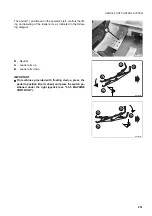
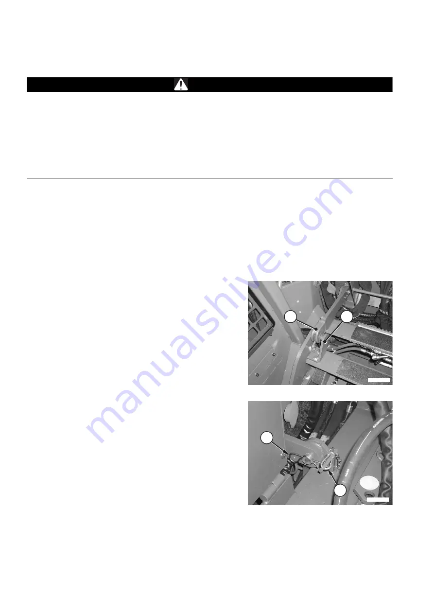
Couple the excavator to the PAN-TACH with the same proce-
dure adopted for the standard equipment and apply the con-
nection tie-rods.
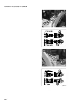
1 - Apply the tie-rods (1) to the excavator and secure them
with the safety pins (2).
2 - Engage the tie-rods with the couplings (3) and connect
the hydraulic circuit.
See "6.2.2 CONNECTING THE HYDRAULIC CIRCUIT".
To disconnect the excavator from the PAN-TACH device, pro-
ceed as follows:
1 - Release the tie rods (1) from the plates (3) and disconnect
the hydraulic circuit of the excavator.
2 - Raise the tie rods (1) and fix them with the safety locks
(4).
RWAA12590
3
1
RWAA12600
2
4
Содержание SK820-5 turbo
Страница 2: ......
Страница 17: ...SAFETY AND ACCIDENT PREVENTION 15...
Страница 19: ...SAFETY NOISE AND VIBRATION PLATES 17 RWA00010 RWA37020...
Страница 21: ...SAFETY NOISE AND VIBRATION PLATES 19 RWA37040 RWA00010 RWA00020...
Страница 53: ...THE MACHINE AND ITS OPERATIONS 51...
Страница 62: ...GENERAL VIEWS 60 10 Left console switches 11 Right console switches RWAA9720 11 RWAA11260 10...
Страница 154: ...152 PAGE INTENTIONALLY LEFT BLANK...
Страница 155: ...MAINTENANCE 153...
Страница 205: ...TECHNICAL SPECIFICATIONS 203...
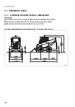
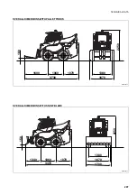
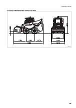
Страница 211: ...TECHNICAL DATA 209 OVERALL DIMENSIONS WITH GRAPPLE FORK RWA36900 1070 2250 1060 1320 3450 180 1670 1460 1380...
Страница 213: ...TECHNICAL DATA 211 SOLID TYRES SIZE MAKE 10x16 5 AIR BOSS...
Страница 214: ...212 PAGE INTENTIONALLY LEFT BLANK...
Страница 215: ...AUTHORISED OPTIONAL EQUIPMENT 213...
Страница 242: ...240 PAGE INTENTIONALLY LEFT BLANK...
Страница 243: ......
Страница 244: ...2004 KOMATSU UTILITY EUROPE S p A All Rights Reserved Printed in Europe...

