Graphic Operator Terminal /
OPERATOR TERMINAL DIAGRAMS
5
This chapter provides the operator terminal diagrams.
5.1
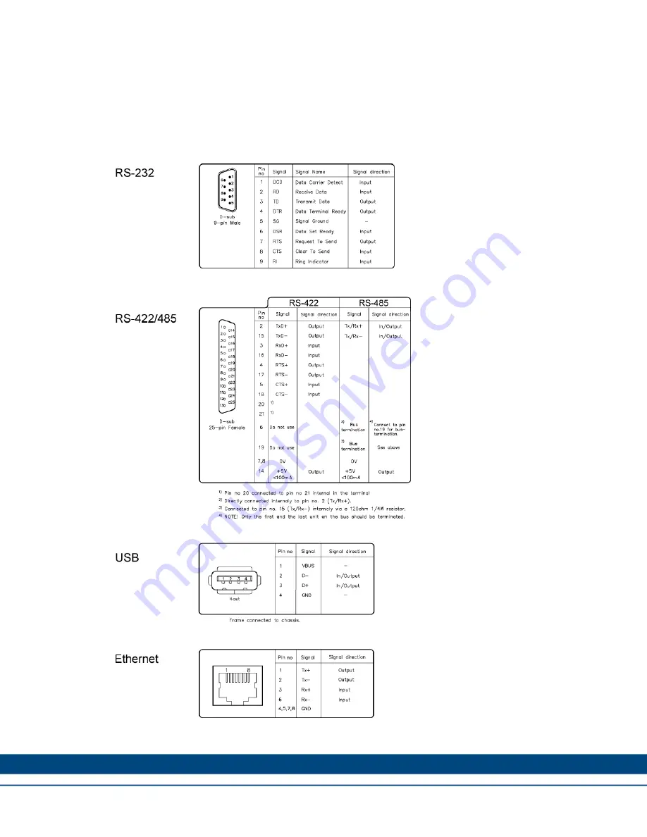
Communication Port Diagrams
15
Страница 1: ...rminal Installation Manual Revision 1 1 August 2011 AKI CDT MOD 04T 3 5 Touchscreen HMI Keep all manuals as a product component during the life span of the product Pass all manuals to future users own...
Страница 2: ...may not be disclosed to third parties translated copied or duplicated in any form in whole or in part without the express written permission of Kollmorgen Registered Trademarks Kollmorgen is a regist...
Страница 3: ...Chemical Resistance 4 1 Metal Casing 12 4 2 Touch Screen and Overlay 13 4 3 Autotex F157 F207 13 4 4 Touch Screen Surface 14 4 5 Touch Screen Protector 14 5 Operator Terminal Diagrams 5 1 Communicati...
Страница 4: ...arefully Check the delivery for transportation damage If damage is found notify the supplier as soon as possible Do not use the graphic operator terminal in an environment with high explosive hazards...
Страница 5: ...correct before connecting the product to the power outlet Peripheral equipment must be appropriate for the application and location 1 2 2 During Use Keep the graphic operator terminal clean Emergency...
Страница 6: ...0 35 inch Space requirements when installing the graphic operator terminal CAUTION The openings on the enclosure are for air convection Do not cover these openings 2 2 Installation Process 1 Unpack an...
Страница 7: ...e controller system have the same electrical grounding reference voltage level otherwise errors in communication may occur B Use an M5 screw and a grounding conductor as short as possible with a cross...
Страница 8: ...ode switches DIP switches located on the rear side of the operator terminal All mode switches must be in OFF position during graphic operator terminal use The mode switches should not be touched unles...
Страница 9: ...ing the file system in the operator panel are deleted when upgrading with Image Loader 1000 Service Menu mode the service menu for the system program is shown Allows the user to set IP configuration e...
Страница 10: ...coated aluminum Weight 0 6 kg Serial port RS422 RS485 25 pin D sub contact chassis mounted female with standard locking screws 4 40 UNC Serial port RS232C 9 pin D sub contact male with standard lockin...
Страница 11: ...the requirements for class II power supplies Ambient temperature Vertical installation 0 to 50 C Horizontal installation 0 to 40 C Storage temperature 20 to 70 C Relative humidity 5 85 non condensed...
Страница 12: ...3 Tap water The powder paint shows limited resistance to the following chemicals at room temperature Chemicals Butanol Nitric acid 3 Hydrochloric acid 5 Nitric acid 10 Isopropyl alcohol Phosphoric ac...
Страница 13: ...Gumption1 SBP 60 951 Ariel powder in solution1 Hydrochloric acid 36 Sulfuric acid 10 Bleach1 Linseed oil Tomato ketchup Castor oil Methanol Tricjloroacetic acid 50 Caustic soda 40 1 Nitric acid 10 Whi...
Страница 14: ...e 5 hours 4 5 Touch Screen Protector It is recommended to use the Touch Screen Protector film that can be ordered from Kollmorgen Solvent Resistance The Touch Screen Protector film withstands exposure...
Страница 15: ...Graphic Operator Terminal OPERATOR TERMINAL DIAGRAMS 5 OPERATOR TERMINAL DIAGRAMS This chapter provides the operator terminal diagrams 5 1 Communication Port Diagrams 15...
Страница 16: ...Graphic Operator Terminal OPERATOR TERMINAL DIAGRAMS 16 5 2 Outline Diagrams...
Страница 17: ...inet Connect a 2 5 mm2 wire between the graphic operator terminal s quick connect plinth and the terminal chassis Connect a 6 or 4 mm2 wire or grounding braid between the terminal s chassis and the cl...
Страница 18: ...assis via a capacitor The graphic operator terminal s Ethernet shield is directly connected to the chassis Check whether the other Ethernet unit has its shield directly grounded or grounded via a capa...
Страница 19: ...ations for the relevant bus standard Use shielded cabling for Ethernet preferably with foil braided shield D sub covers should be shielded and the shield should be connected to the cover 360 where the...
Страница 20: ...vided in the specifications The ambient temperature refers to the temperature in the device cabinet which cools the terminal s electronics In most cases the ambient temperature for the graphic operato...
Страница 21: ...nuous use If a thermostat is installed the fan only needs to come on when needed Large graphic terminals draw only one fifth of the current when the background lighting is off The loss effect drops fr...
Страница 22: ...ds Connect 0 V on the 24 V feed to the ground This offers three advantages Safety is increased The 24 V feed will not be live in the event of a faulty connection or short circuit between 0 V 24 V and...
Страница 23: ...The pair capacitance may not exceed 52 5 pF m and area at least 0 25 mm2 AWG 24 if you want to use the maximum transfer distance and maximum transfer speed 0 V the reference voltage for communication...
Страница 24: ...AKI CDT MOD 04T 3 5 Touch screen HMI A 1 AKI CDT MOD 04T 3 5 Front View 1 155 8mm 119 mm A 2 AKI CDT MOD 04T 3 5 Front View 2 24 Cut out Terminal outline Panel cut out for 3 5 mm display Front View S...
Страница 25: ...erator Terminal APPENDIX A A 3 AKI CDT MOD 04T 3 5 Bottom View COM2 RS232 COM1 RS422 485 24VDC A 4 AKI CDT MOD 04T 3 5 Side View max 7 5 mm material thickness 57 mm Battery DIP switch USB host Etherne...
Страница 26: ...Graphic Operator Terminal APPENDIX A A 5 AKI CDT MOD 04T 3 5 Back View 137 4mm 102 7 mm 9 7 mm 9 mm 8 mm 9 7 mm 26...
Страница 27: ...ugh solutions that are unmatched in performance reliability and ease of use giving machine builders an irrefutable marketplace advantage For assistance with your application needs contact us at 540 63...