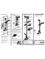


Zone of
Backflow
Risk
Soap Dish Fitted and Shower Fittings Fixed at a
Suitable Height Preventing Dirty Water Backflow
30 mm
Min.
Bath or Shower
Tray FC3
Electric
Shower
25 mm
Min.
25 mm Min.
Toilet or Bidet
FC5
Hand Basin
FC3
Note!
There will be occasions when the soap dish
will not provide a suitable solution for Fluid Category
3 installations. In these instances an outlet double
checkvalve must be fitted, this will increase the
required supply pressure typically by 10 kPa (0.1
bar).
Double checkvalves fitted in the inlet supply to the
appliance cause a pressure build up, which affects
the maximum static inlet pressure for the appliance
and must not be fitted. For Fluid Category 5, double
checkvalves are not suitable.
Installation
Specifications
1.
Installation of the shower fittings must be carried
out in accordance with these instructions by
qualified, competent personnel.
2.
The plumbing installation must comply with all
national or local water regulations and all relevant
building regulations, or any particular regulation
or practice specified by the local water supply
company.
3.
Install the shower fittings over a water catchment
area and position so that the water discharges
down the centre line of the bath, or across the
opening of a shower cubicle. The handset should
direct the water away from the shower unit.
4.
DO NOT
fit any form of flow control in the outlet
pipe work if the shower fittings are installed in
conjunction with a product that requires the fittings
to act as a vent (e.g. an electric shower).
5.
DO NOT
use excessive force when making
connections.
6.
Avoid layouts where the shower hose will be
sharply kinked. This may reduce the life of the
hose.
7.
Special consideration should be given to the fixing
arrangements when installing onto a dry lined, stud
partition, shower cubicle or laminated panel wall
structures. Installers may wish to obtain alternative
proprietary cavity fixings, or choose other options,
however, these methods of fixing are beyond the
scope of this guide.
8.
The position of the shower fittings must provide
a minimum air gap of 25 mm between the
showerhead and the spill over level of any bath,
shower tray or basin. There must be a minimum
distance of 30 mm between the showerhead and
the spill over lever of any toilet, bidet or other
appliance with a Fluid Category 5 backflow risk.
General
Minimum maintained
water pressure
0.1 bar (10 kPa)
Maximum maintained
water pressure
2.0 bar (500 kPa)
2
3
4
5
1.
We recommend that the slide bar is installed with
the ends flush. Mark the wall fixing positions and
drill two holes to suit the wall fixings.
Caution!
Do not drill into cables or pipes in the
wall.
2.
Fit the wall plugs and the mounting brackets and
secure with the wall screws.
Note!
Check for vertical alignment before
tightening. The mounting brackets are slotted to
aid alignment. Then fully tighten.
3.
Fit the clamp bracket (rotate the lever to help with
the installation), the soap dish and the slide bar
support to the slide bar.
4.
Make sure that the wall screws are flush with the
inside edge of the mounting brackets.
5.
Fit the slide bar supports over the mounting
brackets, then adjust the slide bar vertically
ensuring an equal length of slide bar protrudes
from the top and bottom mounting bracket
(or flush with the end of the slide bar for new
installations).
6.
Remove the slide bar assembly carefully,
preventing any further movement between the
slide bar and the slide bar supports.
7.
Tighten the two slide bar clamping screws no
more than half a turn to secure the slide bar
supports to the slide bar.
Caution!
Overtightening these screws will cause
damage.
8.
Install the slide bar assembly onto the mounting
brackets. Tighten the 2 x M4 screws with the
supplied 3 mm hexagonal key.
Caution!
Do not force assembly on to the
mounting brackets, re-align a slide bar support if
required.
9.
Install end cap at the top and soap dish at the
bottom of the slide bar.
Clamp Bracket
Soap Dish
Slide Bar
Clamping Screw
Mounting
Bracket
End Cap
Slide Bar Support
Tighten slide bar clamping
screw no more than 1/2 turn
Slide Bar


