background image


TP-6903  5/16a 

Fuel System Troubleshooting  47 

3.1.  Fuel System Intermittent 

Problems 

 WARNING 


Rotating parts can cause severe injury. 
Stay away while the engine is in operation. 

Keep hands, feet, hair, and clothing away from all moving 
parts to prevent injury. Never operate the engine with 
covers, shrouds, or guards removed. 


Definition:

 The problem is not always observable and 

may or may not store a Diagnostic Trouble Code 
(DTC). 
Intermittent fuel system problems can be the most 
challenging to diagnose. It is important when 
diagnosing intermittent problems to operate the engine 
system while monitoring with Spectrum software and a 
pressure gauge set. 

For example:

 If a lean fuel mixture at full load 

produced a DTC, one of the first things to look at would 
be the fuel pressure. The fuel pressure would need to 
be monitored with Spectrum while the engine is 
operating at full load, not at low or no load because the 
leaning effect does not occur until full load.  

3.2.  Fuel System Basic Checks 

When checking for air or fuel delivery problems, keep 
the process simple and check the basics. Make sure 
that air and fuel are being delivered to the fuel 
regulator. 

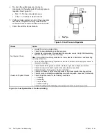
  Use a manometer to verify fuel pressure at the 

fuel pressure port. Fuel delivery to the engine 
must be between 5-11 inches water at all times.  


Figure 3-1 Fuel Shut-off Valve 


Figure 3-2 Dual-Solenoid Fuel Valve 

  Verify that both fuel shut-off valves are working.  

a.  Disconnect the positive (+) battery lead from 

the gas valve terminal. 

b.  Apply 12 VDC to the gas valve terminal and 

listen for an audible click, indicating that the 
valve actuates. 

c.  Replace the gas valve if it does not actuate in 

step 2. 

  Verify that the fuel pressure regulator is working 

and is set correctly for the fuel type used, NG or 
LPG.  

  To check the inlet pressure, connect a 

manometer to the inlet port of the fuel pressure 
regulator. See Figure 3-3. 

  NG = 5–11 inches of water pressure 

  LPG = 5–11 inches of water pressure 


1.

Fuel pressure ports 

1. 

Fuel pressure ports, one on each side 

Содержание KG2204

Страница 1: ...TP 6903 5 16a Engine Fuel System and Diagnostic Code Troubleshooting Engine Models KG2204 KG2204T Propane Liquefied Petroleum Gas LPG and Natural Gas NG Fueled Service ...

Страница 2: ...numbers determine service parts Record the product identification numbers in the spaces below immediately after unpacking the products so that the numbers are readily available for future reference Record field installed kit numbers after installing the kits Engine Identification Record the product identification information from the engine nameplate Manufacturer_______________________________ Mod...

Страница 3: ...nd TMAP Sensors 17 1 13 Oil Pressure Sender 18 1 14 Throttle Body 19 1 15 Throttle Position TP Sensor 19 1 16 Turbocharger KG2204T only 20 1 17 Turbocharger Oil Lines KG2204T only 20 Section 2 Diagnostic Troubleshooting Codes 21 2 1 Introduction 21 2 2 Spectrum Diagnostic Scan Tool DST 21 Section 3 Fuel System Troubleshooting 45 3 1 Fuel System Intermittent Problems 47 3 2 Fuel System Basic Checks...

Страница 4: ...d MAP Sensor Troubleshooting 77 4 11 Throttle Position TP Sensor Troubleshooting 79 Section 5 Installation and Removal Procedures 83 5 1 Air Fuel Mixer Adapter and Throttle Body Assembly 85 5 2 Coolant Temperature CT Sensor 88 5 3 Crankshaft Position CKP Sensor 90 5 4 Electronic Control Module ECM 91 5 5 Fuel Control Valve 92 5 6 Fuel Pressure Regulator 93 5 7 Heated Exhaust Gas Oxygen Sensor HEGO...

Страница 5: ...rking on engine or equipment disable engine as follows 1 Disconnect spark plug leads 2 Disconnect negative battery cable from battery Before disconnecting negative ground cable make sure all switches are OFF If ON a spark will occur at the ground cable terminal which could cause an explosion if hydrogen gas or LPG NG fuel vapors are present Engine Backfire Flash Fire WARNING Risk of Fire Can cause...

Страница 6: ...and tends to settle in low areas where a spark or flame could ignite the gas Do not start or operate this engine in a poorly ventilated area where leaking gas could accumulate and endanger the safety of persons in the area NG Natural Gas is extremely flammable is lighter than air and rises Do not start or operate this engine in a poorly ventilated area where leaking gas could accumulate and endang...

Страница 7: ...ssure WARNING Handling caustic engine fluids and chemical products can cause severe chemical burns nausea fainting or death Most chemicals such as used engine oil antifreeze coolant rustproofing agent inhibiting oil degreasing agent spray paint and adhesives are hazardous to health Read and follow the user information found on the packaging Avoid inhalation and skin contact Use only in well ventil...

Страница 8: ...8 Safety Precautions and Instructions TP 6903 5 16a Notes ...

Страница 9: ...ng follow the troubleshooting steps indicated in the DTC chart If the troubleshooting steps require a component to be replaced refer to Section 5 Installation and Removal Procedures Information in this publication represents data available at the time of print Kohler Co reserves the right to change this publication and the products represented without notice and without any obligation or liability...

Страница 10: ...Kohler Power Systems Netherlands B V Kristallaan 1 4761 ZC Zevenbergen The Netherlands Phone 31 168 331630 Fax 31 168 331631 Asia Pacific Power Systems Asia Pacific Regional Office Singapore Republic of Singapore Phone 65 6264 6422 Fax 65 6264 6455 China North China Regional Office Beijing Phone 86 10 6518 7950 86 10 6518 7951 86 10 6518 7952 Fax 86 10 6518 7955 East China Regional Office Shanghai...

Страница 11: ...and engine sensor data The engine ECM uses this data to regulate the fuel control valve FCV which is used as a fuel trim device and is located at the intake manifold The FCV is an electrically controlled engine vacuum switch When the FCV is energized the valve opens and through a vacuum line connection to the fuel regulator creates a vacuum on the fuel pressure regulator This vacuum causes the reg...

Страница 12: ...or 2 Air fuel mixer 3 Turbocharger 4 TMAP sensor 5 HEGO sensor 6 Throttle body 7 Additional MAP sensor 8 Coolant temperature sensor 9 Crankshaft position sensor 10 Ignition coil 11 Oil cooler adapter 12 ECM 13 Fuel control valve 14 Fuel shut off valve 6 4 3 5 11 10 9 8 2 13 1 7 12 14 Note Air Cleaner removed for clarity ...

Страница 13: ...preset at the factory and should not be adjusted Important The air fuel mixer has been calibrated for the engine s emissions requirements and should never be disassembled or rebuilt If the air fuel mixer is not functioning correctly order a replacement part See the engine parts catalog 1 3 Charge Air Cooler KG2204T only Figure 1 4 Charge Air Cooler The charge air cooler cools the compressed air fu...

Страница 14: ...ening the throttle for fuel flow and initiate the firing of the electronic ignition Cyl 1 Cyl 2 The ignition system is a waste spark design meaning two cylinders fire at the same time One cylinder will fire on its compression stroke and the other will fire on the exhaust stroke waste spark The ECM uses the signal from the crankshaft position sensor to determine where each piston is in relation to ...

Страница 15: ... control valve alters the fuel pressure delivered from the regulator to the air fuel mixer When the engine starts the engine ECM is an open loop state which means fuel delivery is based on a fuel calibration program internal to ECM The program controls the fuel control valve to achieve stoichiometric combustion After the oxygen sensor heats up and the engine coolant temperature reaches a predeterm...

Страница 16: ...uring operation heat from the exhaust increases the temperature of the heating element and activates the sensor Once activated the sensor measures the oxygen content in the exhaust gas and sends a signal to the ECM The ECM uses this signal to adjust the fuel flow to the engine and to prevent the fuel flow from becoming too rich or too lean If the sensor signal indicates that the fuel is too rich o...

Страница 17: ...absolute pressure MAP sensor and the manifold air temperature MAT or intake air temperature IAT sensor The MAP Sensor measures the intake manifold pressure and the MAT or IAT sensor measures the air temperature in the intake manifold The ECM uses the pressure and temperature readings in conjunction with other inputs to estimate the airflow requirement of the engine The MAT sensor uses a variable r...

Страница 18: ...sor prompts the ECM to adjust the air fuel mixture as needed Figure 1 15 Manifold Absolute Pressure MAP Sensor KG2204T 1 13 Oil Pressure Sender Figure 1 16 Oil Pressure Sender The oil pressure sender is used to communicate a low oil pressure condition to the ECM Engine damage can occur if the engine is operated with low oil pressure The engine oil pressure sender is designed to ensure adequate lub...

Страница 19: ...hrottle blade thus increasing or decreasing the fuel supply to the engine The electronic throttle control device incorporates an internal Throttle Position TP sensor which provides output signals to the ECM as to the location of the throttle shaft and blade The TP sensor information is used by the ECM to correct for speed and load control 1 15 Throttle Position TP Sensor Figure 1 18 Throttle Posit...

Страница 20: ...er bypasses exhaust gas around the turbine when the boost pressure reaches a maximum limit Use Spectrum software to check the boost pressure and adjust the wastegate linkage if necessary to achieve a maximum boost pressure of 180 kPa absolute 1 17 Turbocharger Oil Lines KG2204T only Figure 1 21 Turbocharger oil lines The turbocharger bearings require oil for lubrication and cooling Oil is fed to t...

Страница 21: ...ies Inc Refer to the Spectrum instruction manual for software installation and operation Use Spectrum to View active and historic diagnostic troubleshooting codes DTCs Monitor feedback from the sensors Plot sensor feedback to a chart Note Spectrum software software password instruction manual and a Kvaser CAN Bus driver are available at http www impco ws spectrum test tools asp Download Spectrum S...

Страница 22: ...2 Not applicable Not applicable P0038 3232 3 HO2S Heater Control Circuit High Bank 1 Sensor 2 Not applicable Not applicable P0051 3261 4 HO2S Heater Control Circuit Low Bank 2 Sensor 1 Not applicable Not applicable P0052 3261 3 HO2S Heater Control Circuit High Bank 2 Sensor 1 Not applicable Not applicable P0057 3271 4 HO2S Heater Control Circuit Low Bank 2 Sensor 2 Not applicable Not applicable P0...

Страница 23: ...e TMAP sensor leads Refer to Section 4 10 Replace the TMAP sensor Refer to Section 5 10 P0116 110 13 Engine Coolant Temperature Circuit Range Performance Problem Problem with the CT sensor or leads Check CT sensor leads Refer to Section 4 3 Replace CT sensor Refer to Section 5 2 P0117 110 4 Engine Coolant Temperature Circuit Low Input Problem with the CT sensor or leads Check CT sensor leads Refer...

Страница 24: ...ge B1S1 Problem with the HEGO sensor or leads Troubleshoot the HEGO sensor for bad leads Refer to Section 4 7 Replace the HEGO sensor Refer to Section 5 7 P0132 3217 3 HEGO sensor Circuit High Voltage B1S1 Problem with the HEGO sensor or leads Troubleshoot the HEGO sensor for bad leads Refer to Section 4 7 Replace the HEGO sensor Refer to Section 5 7 P0133 3217 13 HEGO sensor Circuit Slow Response...

Страница 25: ... regulator Check fuel shutoff valve Confirm fuel quality and fuel pressure P0172 1695 15 System Too Rich Bank 1 Problem with fuel delivery or fuel feedback control Check for other DTC codes or misfires Check for exhaust restrictions Check fuel system for restrictions Confirm fuel quality and fuel pressure Check fuel pressure regulator Troubleshoot the HEGO sensor for bad leads Refer to Section 4 7...

Страница 26: ...tch B Circuit Intermittent Problem with the TP sensor in the throttle body or the leads Troubleshoot the TP sensor leads Refer to Section 4 11 Replace the throttle body Refer to Section 5 1 P0234 1127 7 Turbo Super Charger Overboost Condition KG2204T engine with turbocharger only Problem in the turbocharger wastegate control circuit Check wastegate and solenoid plumbing Check wastegate solenoid op...

Страница 27: ...or Circuit High Not applicable Not applicable P0272 654 7 Cylinder 4 Contribution Balance Not applicable Not applicable P0273 655 4 Cylinder 5 Injector Circuit Low Not applicable Not applicable P0274 655 3 Cylinder 5 Injector Circuit High Not applicable Not applicable P0275 655 7 Cylinder 5 Contribution Balance Not applicable Not applicable P0276 656 4 Cylinder 6 Injector Circuit Low Not applicabl...

Страница 28: ...rcuit Low Not applicable Not applicable P0328 731 3 Knock Sensor 1 Circuit High Not applicable Not applicable P0332 731 4 Knock Sensor 2 Circuit Low Not applicable Not applicable P0333 731 3 Knock Sensor 2 Circuit High Not applicable Not applicable P0335 636 31 Crankshaft Position Sensor A Circuit Problem with the crank position sensor or the leads Troubleshoot the CKP sensor leads Refer to Sectio...

Страница 29: ... 4 3 Check the thermostat and replace if needed Refer to the Engine Service Manual P0522 100 4 Engine Oil Pressure Sensor Switch Low Voltage Problem with the oil pressure sender or the leads Check the oil pressure sender leads Refer to Section 4 9 Replace the oil pressure sender Refer to Section 5 9 P0523 100 3 Engine Oil Pressure Sensor Switch High Voltage Problem with the oil pressure sender or ...

Страница 30: ... RAM Error There is a problem with the ECM RAM Clear the DTC code and turn the ECM power off Wait fifteen minutes and check if the code is regenerated Replace the ECM Refer to Section 5 4 P0605 No J1939 DTC Internal Control Module Read Only Memory ROM Error There is a blank or corrupted operating program Clear the DTC code and turn the ECM power off Wait fifteen minutes and check if the code is re...

Страница 31: ... Circuit Low Not applicable Not applicable P0647 876 3 A C Clutch Relay Control Circuit High Not applicable Not applicable P0650 1213 31 Malfunction Indicator Lamp MIL Control Circuit Not applicable Not applicable P0652 3510 4 Sensor Reference Voltage B Circuit Low Problem with 5 V sensor power supply circuit Power supply is less than 4 6 V Check electrical connection at ECM for sensor power suppl...

Страница 32: ...the battery alternator and the ECM power input pin P0687 1485 3 ECM PCM Power Relay Control Circuit High Problem with the power control relay circuit Check power control relay and leads P0691 1071 4 Fan 1 Control Circuit Low Not applicable Not applicable P0692 1071 3 Fan 1 Control Circuit High Not applicable Not applicable P0693 1071 4 Fan 2 Control Circuit Low Not applicable Not applicable P0694 ...

Страница 33: ...P1135 3217 2 Oxygen Sensor 1 Bank 1 Lean Shift Diagnostic not set Problem with exhaust leaks or poor HEGO sensor performance Check for exhaust leaks before or near the HEGO sensor Check for intake manifold leaks Verify that the HEGO sensor is installed securely Troubleshoot the HEGO sensor for bad leads Refer to Section 4 7 Replace the HEGO sensor Refer to Section 5 7 P1136 3217 2 Oxygen Sensor 1 ...

Страница 34: ...le Not applicable P1609 1634 31 Calibration Firmware Mismatch ECM not flashed correctly Re Flash or replace the ECM P1630 3464 0 Electronic Throttle Driver Overheat Leads bad throttle body Throttle driver temperature has exceeded safe operating limits Troubleshoot the TP sensor leads Refer to Section 4 11 Replace the throttle body Refer to Section 5 1 P1631 3464 0 Electronic Throttle Driver Overhe...

Страница 35: ...ottle body if the code continues to occur Refer to Section 5 1 P2109 3464 13 Throttle Position Sensor A Minimum Stop Performance Problem with throttle body or leads Check for smooth throttle operation Troubleshoot the TP sensor leads Refer to Section 4 11 Perform manual throttle zero process using the scan tool Replace the throttle body if the code continues to occur Refer to Section 5 1 P2111 346...

Страница 36: ...Position Sensor Switch D Circuit High Input Not applicable Not applicable P2127 2972 4 Throttle Pedal Position Sensor Switch E Circuit Low Input Not applicable Not applicable P2128 2972 3 Throttle Pedal Position Sensor Switch E Circuit High Input Not applicable Not applicable P2132 2973 4 Throttle Pedal Position Sensor Switch F Circuit Low Input Not applicable Not applicable P2133 2973 3 Throttle ...

Страница 37: ...3464 14 Throttle Actuator Control System High Airflow Detected Throttle body damage or air leak between the throttle and engine Check for smooth throttle operation Check for vacuum hose leaks Troubleshoot the TP sensor leads Refer to Section 4 11 Replace the throttle body Refer to Section 5 1 P2174 3464 14 Throttle Actuator Control System Sudden Low Airflow Detected Throttle body damage or air blo...

Страница 38: ... System Too Lean at Idle Problem with the closed loop feedback control Check for misfires Check fuel quality Check fuel pressure regulator and outlet pressure Check for exhaust leaks Check for intake manifold leaks Troubleshoot the HEGO sensor for bad leads Refer to Section 4 7 Replace the HEGO sensor Refer to Section 5 7 P2188 1695 16 System Rich at Idle Problem with the closed loop feedback cont...

Страница 39: ...r for bad leads Refer to Section 4 7 Replace the HEGO sensor Refer to Section 5 7 P2231 3217 14 HEGO sensor Signal Circuit Shorted to Heater Circuit HEGO heater causing interference with the HEGO signal Problem with HEGO sensor or leads Troubleshoot the HEGO sensor for bad leads Refer to Section 4 7 Replace the HEGO sensor Refer to Section 5 7 P2243 3217 5 Oxygen Sensor Reference Circuit Bank 1 Se...

Страница 40: ...ion coil and leads Refer to Section 4 8 Swap the positive and negative coil leads to see if leads are reversed Replace the ignition coil Refer to the Section 5 8 P2302 1393 31 Ignition Coil A Secondary Circuit No spark detected by the ECM Check for a disconnected spark plug lead Check the spark plug lead continuity Check for worn spark plug electrodes Replace the spark plug Replace the ignition co...

Страница 41: ...95 31 Ignition Coil C Secondary Circuit No spark detected by the ECM Troubleshoot the ignition coil and leads Refer to Section 4 8 Check for a disconnected spark plug lead Check the spark plug lead continuity Check for worn spark plug electrodes Replace the spark plug Replace the ignition coil Refer to the Section 5 8 P2309 1271 5 Ignition Coil D Primary Control Circuit Low No spark detected by th...

Страница 42: ... applicable P2318 1274 5 Ignition Coil G Primary Control Circuit Low Not applicable Not applicable P2319 1274 6 Ignition Coil G Primary Control Circuit High Not applicable Not applicable P2320 1398 31 Ignition Coil G Secondary Circuit Not applicable Not applicable P2321 1275 5 Ignition Coil H Primary Control Circuit Low Not applicable Not applicable P2322 1275 6 Ignition Coil H Primary Control Cir...

Страница 43: ...vel Low Not applicable Not applicable P2626 3217 5 HEGO sensor Pumping Current Trim Circuit Open Problem with the HEGO sensor Troubleshoot the HEGO sensor for bad leads Refer to Section 4 7 Replace the HEGO sensor Refer to Section 5 7 P2666 2807 4 Fuel Shutoff Valve B Control Circuit Low Not applicable Not applicable P2667 2807 3 Fuel Shutoff Valve B Control Circuit High Not applicable Not applica...

Страница 44: ...44 Diagnostic Troubleshooting Codes TP 6903 5 16a Notes ...

Страница 45: ...sparks near fuels or the fuel system Servicing the fuel system A flash fire can cause severe injury or death Do not smoke or permit flames or sparks near the carburetor fuel line fuel filter fuel pump or other potential sources of spilled fuels or fuel vapors Catch fuels in an approved container when removing the fuel line or carburetor Servicing the air cleaner A sudden backfire can cause severe ...

Страница 46: ...hemical products can cause severe chemical burns nausea fainting or death Most chemicals such as used engine oil antifreeze coolant rustproofing agent inhibiting oil degreasing agent spray paint and adhesives are hazardous to health Read and follow the user information found on the packaging Avoid inhalation and skin contact Use only in well ventilated areas and use a protective mask when spraying...

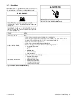
Страница 47: ... because the leaning effect does not occur until full load 3 2 Fuel System Basic Checks When checking for air or fuel delivery problems keep the process simple and check the basics Make sure that air and fuel are being delivered to the fuel regulator Use a manometer to verify fuel pressure at the fuel pressure port Fuel delivery to the engine must be between 5 11 inches water at all times Figure 3...

Страница 48: ...ng between lean and rich cycling of voltage Note Normal HEGO switching indicates the fuel system is in closed loop and operating correctly at that time Take a data snapshot using Spectrum under the condition that the symptom occurs to review at a later time Visual and Physical Checks Check that the ECM ground connection is clean tight and in its proper location Check the vacuum hoses for splits ki...

Страница 49: ...es Check the fuel system pressures Ignition System Checks Check for the proper ignition voltage output Verify that the spark plugs are correct Check the spark plugs for the following conditions o Wet plugs oil fouling o Cracks o Wear o Improper gap o Burned electrodes o Heavy deposits Check for bare or shorted ignition leads Check for loose ignition coil connections at the coil Engine Mechanical C...

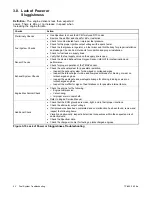
Страница 50: ...ttle body and air filter assembly Check the fuel system pressures Ignition System Checks Note Natural Gas and Liquefied Petroleum Gas require higher secondary ignition system voltages than the equivalent gasoline operating conditions Check for the proper ignition voltage output Verify that the spark plugs are the correct type and properly gapped Check the spark plugs for the following conditions o...

Страница 51: ...s are the correct type and properly gapped Remove the spark plugs and check for the following conditions o Insulation cracks o Wear o Improper gap o Burned electrodes o Heavy deposits Visually physically inspect the ignition for the following o Ignition leads for arcing and proper routing o Cross firing o Ignition coils for cracks or carbon tracking Engine Mechanical Checks Perform a cylinder comp...

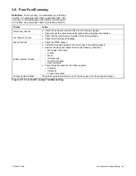
Страница 52: ...lator or a restriction in the fuel system Check the TMAP sensor response and accuracy Check shut off electrical connections Check the fuel pressure regulator air fuel mixer and throttle body for proper installation and leakage Ignition System Checks Check for proper ignition output voltage with a spark tester Verify that the spark plugs are the correct type and properly gapped Check for faulty spa...

Страница 53: ...ubleshooting Checks Action Preliminary Check None Ignition System Checks Check for proper ignition output voltage with a spark tester Check the spark plug leads by connecting an ohmmeter to the ends of each lead in question If the meter reads over 15 000 ohms replace the leads Check the connection at ignition coil Check for deteriorated spark plug lead insulation Remove the plugs and inspect them ...

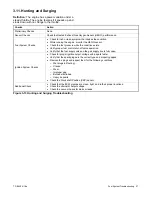
Страница 54: ...or contamination and performance Check for proper operation of the TMAP sensor Exhaust System Checks Check the exhaust system for a possible restriction o Inspect the exhaust system for damaged or collapsed pipes o Inspect the turbocharger turbine and compressor blades for binding or wear on turbocharged engines o Inspect the wastegate and wastegate linkage for sticking binding or wear on turbocha...

Страница 55: ...m hoses for splits kinks and proper connections Fuel System Checks Check that the fuel pressure regulator is functioning properly Check the fuel system for leakage Sensor Checks Check the TMAP sensor Ignition System Checks Verify that the spark plugs are the correct type and properly gapped Remove the plugs and inspect them for the following conditions o Wet plugs oil fouling o Cracks o Wear o Imp...

Страница 56: ...pressure regulator Perform a cylinder compression test Refer to Engine Service Manual Check the regulator fuel pressure Check the fuel pressure regulator air fuel mixer and throttle body for proper installation and leakage Ignition System Checks Check for proper ignition output voltage with a spark tester Verify that the spark plugs are the correct type and properly gapped Remove the plugs and ins...

Страница 57: ... sensor Check the fuel pressure while the condition exists Verify proper fuel control shut off valve operation Verify that the fuel supply valve on the gas supply line is fully open Ignition System Checks Check for proper ignition output voltage with a spark tester Verify that the spark plugs are the correct type and properly gapped Remove the plugs and inspect them for the following conditions o ...

Страница 58: ...58 Fuel System Troubleshooting TP 6903 5 16a Notes ...

Страница 59: ...an cause severe injury or death Do not operate the engine with the air cleaner removed WARNING Avoid possible death or serious injury Pinch and entanglement hazards Never check drive belt tension while the engine is running WARNING Rotating parts can cause severe injury Stay away while the engine is in operation Keep hands feet hair and clothing away from all moving parts to prevent injury Never o...

Страница 60: ...ntact with skin Thoroughly wash your hands and nails with soap and water shortly after handling used engine oil Wash or dispose of clothing or rags containing used engine oil Dispose of used engine oil in accordance with applicable laws and regulations Contact your local recycling center for disposal information and locations WARNING Electrical shock can cause injury Do not touch wires while engin...

Страница 61: ...ing fuel may enter the air intake manifold or the air cleaner and cause a backfire Make sure that the fuel supply is turned OFF and that the fuel shut off valves are DISCONNECTED from the power source BEFORE turning the ECM power on These instructions explain how to turn the ECM power on and off on generator sets equipped with the Kohler RDC2 generator set controller To turn the ECM power ON and O...

Страница 62: ...or guards removed Figure 4 3 Coolant Temperature Sensor Wiring Diagram Temp C Temp F Ohms 150 302 57 50 110 230 144 25 100 212 186 50 90 194 243 25 80 176 322 50 70 158 435 75 60 140 595 50 45 113 987 50 30 86 1707 00 5 41 4712 00 Figure 4 4 CT Sensor Resistance Refer to Figure 4 3 Coolant Temperature Sensor Wiring Diagram and follow the steps in the troubleshooting chart to verify that The CT sen...

Страница 63: ...ce the CT sensor Refer to Section 5 2 Is the replacement complete Go to the next step Remove all test equipment except Spectrum Connect any disconnected components Using Spectrum clear DTC information from the ECM Turn the ECM power OFF and wait 30 seconds Start the engine and operate to full operating temperature Use Spectrum to verify if the DTC code was regenerated Observe engine performance Do...

Страница 64: ...arts can cause severe injury Stay away while the engine is in operation Keep hands feet hair and clothing away from all moving parts to prevent injury Never operate the engine with covers shrouds or guards removed Figure 4 7 Crankshaft Position Sensor Wiring Diagram Refer to Figure 4 7 and follow the steps in the troubleshooting chart to verify that The sensor leads have continuity no open circuit...

Страница 65: ...sor Refer to Section 5 3 Is the replacement complete Go to the next step Remove all test equipment except Spectrum Connect any disconnected components Using Spectrum clear DTC information from the ECM Turn the ECM power OFF and wait 30 seconds Start the engine and operate to full operating temperature Observe the engine performance After operating the engine check for any stored codes Does the eng...

Страница 66: ...replacement of good parts Faulty Electrical Connections or Wiring Faulty electrical connections or wiring can cause most intermittent problems Check the suspected circuit for the following conditions Connectors poorly mated terminals not fully seated in the connector backed out Terminals not properly formed or damaged Lead terminals poorly connected Terminal tension is insufficient Carefully remov...

Страница 67: ...t or operate this engine in a poorly ventilated area where leaking gas could accumulate and endanger the safety of persons in the area To ensure personal safety installation and repair of LPG NG fuel supply systems must be performed only by qualified LPG NG system technicians Improperly installed and maintained LPG NG equipment could cause the fuel supply system or other components to malfunction ...

Страница 68: ... the problem as required Go to the next step Replace the fuel control valve Refer to Section 5 5 Go to the next step Remove all test equipment except Spectrum Connect any disconnected components Using Spectrum software clear DTC information from the ECM Turn the ECM power OFF and wait 30 seconds Start the engine and operate to full operating temperature Observe the engine performance After operati...

Страница 69: ...or sensor troubleshooting fuel may enter the air intake manifold or the air cleaner and cause a backfire Make sure that the fuel supply is turned OFF and that the fuel shut off valves are DISCONNECTED from the power source BEFORE turning the ECM power on Figure 4 15 HEGO Sensor Wiring Diagram Refer to Figure 4 15 and follow the steps in the troubleshooting chart to verify that The HEGO sensor is w...

Страница 70: ...18 and HEGO connector pin 4 o P27 82 and HEGO connector pin 2 o P26 51 and HEGO connector pin 3 o P26 65 and HEGO connector pin 1 Does the DVOM show continuity Go to the next step Repair any open circuits as necessary Connect the wire harness to the ECM With the ECM power turned OFF disconnect the wire harness from the HEGO sensor Check for continuity between HEGO connector pin 4 and engine ground...

Страница 71: ... codes Does the engine operate normally with no stored codes The system is OK Restart HEGO troubleshooting procedure Replace the ECM Refer to Section 5 4 Is the replacement complete Go to the next step Remove all test equipment except Spectrum Connect any disconnected components Using Spectrum clear DTC information from the ECM Turn the ECM power OFF and wait 30 seconds Start the engine and operat...

Страница 72: ... sure that the fuel supply is turned OFF and that the fuel shut off valves are DISCONNECTED from the power source BEFORE turning the ECM power on WARNING Rotating parts can cause severe injury Stay away while the engine is in operation Keep hands feet hair and clothing away from all moving parts to prevent injury Never operate the engine with covers shrouds or guards removed Figure 4 18 Ignition C...

Страница 73: ... pull the ignition coil off of its spark plug to verify if it s sparking This method can damage an ignition coil Before diagnosing no spark ignition issues make sure the ECM is receiving the initialization signal on P26 3 and P26 65 and the crank position sensor is working If spark is present the ignition coil is likely good Use an HEI spark tester when checking for engine spark Pull the leads off...

Страница 74: ...g the intake manifold Turn the ECM power ON Check for voltage on connector pins 3 and 4 Does the DVOM show voltage Go to the next step Repair the open circuit as necessary Replace the ignition module Refer to Section 5 8 Is the replacement complete Go to the next step Remove all test equipment except Spectrum Connect any disconnected components Using Spectrum clear DTC information from the ECM Tur...

Страница 75: ...am If an oil pressure fault occurs always verify the oil pressure before checking for an electrical malfunction If there are no problems with the oil pressure level indicating a problem with the sensor proceed with the following oil pressure sender troubleshooting Refer to Figure 4 21 and follow the steps in the troubleshooting chart to verify that The engine oil pressure is correct The oil pressu...

Страница 76: ...connector P26 pin 31 Does the DVOM show continuity Go to the next step Repair the shorted circuit as necessary Turn the ECM power OFF Using a DVOM check for continuity between the oil pressure sender connector pin and engine ground Does the DVOM show continuity Repair the shorted circuit as necessary Go to the next step Replace the oil pressure sender Refer to Section 5 9 Is the replacement comple...

Страница 77: ...shrouds or guards removed Figure 4 25 TMAP Sensor Wiring Diagram Figure 4 26 MAP Sensor Wiring Diagram KG2204T Use the following steps to troubleshoot the TMAP and MAP sensors Check both the MAP and IAT portions of the TMAP sensor Refer to Figure 4 25 and follow the steps in the troubleshooting chart to verify that The TMAP sensor is working correctly and is not damaged The sensor leads have conti...

Страница 78: ...necessary With the ECM power OFF check for continuity between the following TMAP or MAP connector pin 1 and engine ground TMAP or MAP connector pin 2 and engine ground TMAP connector pin 3 and engine ground Does the DVOM show continuity Repair the shorted circuit as necessary Go to the next step Using a DVOM check for continuity between TMAP connector pins 1 and 3 Does the DVOM show continuity Rep...

Страница 79: ...ng gas leaks Observe federal state and local laws governing LPG NG fuel storage and systems WARNING Hot parts can cause severe burns Do not touch engine while operating or just after stopping Never operate engine with heat shields or guards removed Servicing the exhaust system Hot parts can cause severe injury or death Do not touch hot engine parts The engine and exhaust system components become e...

Страница 80: ...Figure 4 29 and follow the steps in the troubleshooting chart to check the throttle position sensors TPS1 and TPS2 Verify that The TP sensor is working correctly and is not damaged The sensor leads have continuity no open circuits The sensor leads are not shorted Closed Partially Open Fully Open TPS1 0V Between 0V 5V 5V TPS2 5V Between 5V 0V 0V P26 70 Sensor ground ETC P27 112 ETC 1 2 104 40A 3 4 ...

Страница 81: ...ir the open circuit as necessary With the ECM power OFF check for continuity between the following o Sensor connector pin 1 and engine ground o Sensor connector pin 2 and engine ground o Sensor connector pin 3 and engine ground o Sensor connector pin 4 and engine ground o Sensor connector pin 5 and engine ground o Sensor connector pin 6 and engine ground Does the DVOM show continuity Repair the sh...

Страница 82: ...ored codes The system is OK Go to the next step Replace the ECM Refer to Section 5 4 Is the replacement complete Go to the next step Remove all test equipment except Spectrum Connect any disconnected components Using Spectrum clear DTC information from the ECM Turn the ECM power OFF and wait 30 seconds Start the engine and operate to full operating temperature Use Spectrum to verify if the DTC cod...

Страница 83: ...e can cause severe injury or death Do not smoke or permit flames or sparks near the carburetor fuel line fuel filter fuel pump or other potential sources of spilled fuels or fuel vapors Catch fuels in an approved container when removing the fuel line or carburetor Servicing the air cleaner A sudden backfire can cause severe injury or death Do not operate the engine with the air cleaner removed WAR...

Страница 84: ... the fuel supply system or other components to malfunction causing gas leaks Observe federal state and local laws governing LPG NG fuel storage and systems Used engine oil Contact with used engine oil may cause severe skin irritation Repeated and prolonged skin exposure may have other health risks Used engine oil is a suspected carcinogen Avoid contact with skin Thoroughly wash your hands and nail...

Страница 85: ...ed assembly and disassembly instructions 5 1 1 Throttle Body and Air Fuel Mixer Removal KG2204 Figure 5 1 Component Exploded View KG2204 Note To loosen the four mounting bolts securing the air fuel mixer valve and throttle body assembly to the upper intake manifold cut off a hex wrench as needed to fit into the tight location Make sure that the engine is off If the engine is used as part of a gene...

Страница 86: ...e and fuel intake hoses to the mixer Install wire harness to throttle position sensor Reconnect the battery If the engine is used as part of a generator set re apply the AC power supply to the generator set by closing the upstream circuit breaker Turn on the fuel supply Start the engine and check for leaks with the engine running Turn off the engine 5 1 3 Throttle Body Removal KG2204T Figure 5 2 T...

Страница 87: ...upply to the generator set by closing the upstream circuit breaker Turn on the fuel supply Start the engine and check for leaks with the engine running Turn off the engine 5 1 5 Air Fuel Mixer Removal KG2204T Note For turbocharger removal and installation instructions refer to the engine service manual Figure 5 3 Air Fuel Mixer Exploded View KG2204T Make sure that the engine is off If the engine i...

Страница 88: ...turbocharger Use caution not to damage O rings Tighten the clamp Attach the air intake and fuel intake hoses to the mixer Reconnect the battery If the engine is used as part of a generator set re apply the AC power supply to the generator set by closing the upstream circuit breaker Turn on the fuel supply Start the engine and check for leaks with the engine running Turn off the engine 5 2 Coolant ...

Страница 89: ...ne starting battery negative lead first Shut off the fuel supply Drain the coolant Locate the CT sensor on the coolant below the air fuel mixer Remove the wire harness from the CT sensor Unscrew the sensor from the engine 5 2 2 Installation Procedure Apply a light coat of Loctite 567 or equivalent pipe thread sealant on the threads of the ECT Install the CT sensor into the engine and torque until ...

Страница 90: ...rcuit breaker Disconnect the engine starting battery negative lead first Shut off the fuel supply Remove three electrical harness clamp bolts flat washers and lock washers from crankshaft position sensor wiring harness Remove the mounting bolt flat washer and lock washer from the crankshaft position sensor Remove the sensor 5 3 2 Installation Procedure Install the crankshaft position sensor to the...

Страница 91: ...ape to successfully bond the ideal temperature range is 21 C 38 C 70 F 100 F and the minimum temperature requirement is 10 C 50 F Apply black bonding tape Kohler part number 32000 00110 to the back of the ECM Press and hold the ECM onto the mounting bracket for 1 minute Plug the connectors into the ECM and push the locks into place Reconnect the battery If the engine is used as part of a generator...

Страница 92: ...s leaks Observe federal state and local laws governing LPG NG fuel storage and systems 5 5 1 Removal Procedure Make sure that the engine is off If the engine is used as part of a generator set disconnect AC power to the generator set by opening the upstream circuit breaker Disconnect the engine starting battery negative lead first Shut off the fuel supply Disconnect wire harness Disconnect the vac...

Страница 93: ...t could cause the fuel supply system or other components to malfunction causing gas leaks Observe federal state and local laws governing LPG NG fuel storage and systems 5 6 1 Removal Procedure Make sure that the engine is off If the engine is used as part of a generator set disconnect AC power to the generator set by opening the upstream circuit breaker Disconnect the engine starting battery negat...

Страница 94: ...fittings on the fuel pressure regulator and tighten the hose clamps Position the fuel line hose onto the hose adapter and tighten the fuel line hose clamp to secure Reconnect the battery If the engine is used as part of a generator set re apply the AC power supply to the generator set by closing the upstream circuit breaker Reconnect the fuel line and turn on the fuel supply Turn the ECM power ON ...

Страница 95: ...s or inappropriate RTV room temperature vulcanization sealers can contaminate the HEGO sensor Contaminated HEGO sensors can produce false or high readings resulting in poor fuel mixtures and severe performance problems Always verify that the sealer is safe to use with the HEGO sensor before using Before installing the HEGO sensor lubricate the threads with an appropriate anti seize compound Avoid ...

Страница 96: ...ness and the spark plug leads from the ignition coil Remove the four ignition coil mounting bolts flat washers lock washers and nuts that secure the ignition coil to the bracket Remove the ignition coil 5 8 2 Installation Procedure Position the ignition coil on the bracket Secure the ignition coil with four ignition coil mounting bolts flat washers lock washers and nuts Connect the wire harness an...

Страница 97: ...dling used engine oil Wash or dispose of clothing or rags containing used engine oil Dispose of used engine oil in accordance with applicable laws and regulations Contact your local recycling center for disposal information and locations 5 9 1 Removal Procedure Make sure that the engine is off If the engine is used as part of a generator set disconnect AC power to the generator set by opening the ...

Страница 98: ...ove TMAP Sensor by pulling straight up with a slight rocking motion 5 10 2 Installation Procedure Lightly apply petroleum jelly to the O ring on the TMAP sensor Install the TMAP sensor and secure with the retaining screw Torque the retaining screw to 9 9 Nm 7 3 ft lb Reconnect the wire harness Reconnect the battery If the engine is used as part of a generator set re apply the AC power supply to th...

Страница 99: ...the retaining screw Remove MAP Sensor by pulling straight up with a slight rocking motion 5 11 2 Installation Procedure Lightly apply petroleum jelly to the O ring on the MAP sensor Install the MAP sensor and secure with the retaining screw Tighten the retaining screw to 9 9 Nm 7 3 ft lb Reconnect the wire harness Reconnect the battery If the engine is used as part of a generator set re apply the ...

Страница 100: ...100 TP 6903 Notes ...

Страница 101: ... into Cast Iron or Steel Assembled into Aluminum Grade 2 or 5 Grade 2 Grade 5 Grade 8 8 32 N m in lb 1 8 16 2 3 20 See Note 3 10 24 N m in lb 2 9 26 3 6 32 10 32 N m in lb 2 9 26 3 6 32 1 4 20 N m in lb 6 8 60 10 8 96 14 9 132 1 4 28 N m in lb 8 1 72 12 2 108 16 3 144 5 16 18 N m in lb 13 6 120 21 7 192 29 8 264 5 16 24 N m in lb 14 9 132 23 1 204 32 5 288 3 8 16 N m ft lb 24 0 18 38 0 28 53 0 39 ...

Страница 102: ...ate preload of 90 of the yield strength and a friction coefficient of 0 125 Size Torque Measurement Assembled into Cast Iron or Steel Assembled into Aluminum Grade 5 8 or 8 8 Grade 5 8 Grade 8 8 Grade 10 9 M6 x 1 00 N m ft lb 6 2 4 6 12 9 13 6 10 See Note 3 M8 x 1 25 N m ft lb 15 0 11 29 6 22 33 0 24 M8 x 1 00 N m ft lb 16 0 11 24 0 18 34 0 25 M10 x 1 50 N m ft lb 30 0 22 52 5 39 65 0 48 M10 x 1 2...

Страница 103: ... cooled cyl cylinder D A digital to analog DAC digital to analog converter dB decibel dB A decibel A weighted DC direct current DCR direct current resistance deg degree dept department dia diameter DI EO dual inlet end outlet DIN Deutsches Institut fur Normung e V also Deutsche Industrie Normenausschuss DIP dual inline package DPDT double pole double throw DPST double pole single throw DS disconne...

Страница 104: ...pan head machine screw PLC programmable logic control PMG permanent magnet generator pot potentiometer potential ppm parts per million PROM programmable read only memory psi pounds per square inch psig pounds per square inch gauge pt pint PTC positive temperature coefficient PTO power takeoff PVC polyvinyl chloride qt quart quarts qty quantity R replacement emergency power source rad radiator radi...

Страница 105: ...Notes ...

Страница 106: ...Notes ...

Страница 107: ......

Страница 108: ...Asia Pacific Headquarters 7 Jurong Pier Road Singapore 619159 Phone 65 6264 6422 Fax 65 6264 6455 TP 6903 5 16a 2015 2016 by Kohler Co All rights reserved For the nearest KOHLER authorized installation service and sales dealer in the US and Canada Call 1 800 544 2444 or visit KOHLERPower com ...

Отзывы: