
1265599-2A-A
2
1265599-2A-A
3
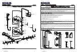
How to Install the Faucet
To perform installation, installer must provide G1/2
˝
female supply fittings(1),
spaced 150mm apart and horizontally. The supply fittings should be vertical and
not beyond the finished wall. Hot supply pipe must be located on the left.
Flush the water supply pipes thoroughly to remove debris.
Install the two offset connectors(2) into the hot and cold supply pipes. Use
appropriate thread sealants or thread tape on pipe threads. Adjust the
center-to-center distance between the connectors to 150mm and horizontally.
They should extend 29mm beyond the finished wall. Thread the escutcheons(3)
onto the connectors until they are against the finished wall.
Put the washers(4) into the nuts(5), thread the nuts to connectors. Tighten the
nuts with strap wrench or soft cloth between product and regular wrench.
How to Install the Column
Select a location in vertical wall to install shower column according to rough-in
dimensions. Drill the lower hole as anchors(6) diameter and lower base(8-1)
position in the finished wall(
NOTE:
The arrow in the base is upward). Press
anchors into the hole, secure the base by the screws(7).
Rehearse the slide bar kit(9) installation for the upper base(8-2) mounting location
determination. Slide the tube joint(10) onto the slide bar kit, and connect them to
the base(
NOTE:
The arrow in the base is up). Install the screws(12) into the tube
joint with the hex wrench(11), and tighten them.
Place the slide bar and the body against the finished wall. Connect the lower base
and the diverter body kit(13). Position and tighten them by hex wrench. Mark the
hole of upper base(8-2) with a pencil. Uninstall the slide bar kit and tube joint.
(
NOTE:
Don’t lose the screws.)
Drill holes on the mark. Press the anchors into the holes. Secure the upper
base(8-2) by the screws. Install the tube joint(10) to the base(8-2) and tighten
them by screws. Reinstall the slide bar kit with escutcheons(14) to the bases.
Tighten the screws with the hex wrench. Screw the escutcheons with the bases
until against the finished wall.
Install the tube kit(15) into the slide bar kit. Install the nut(16) onto the tube kit
with soft cloth between internal hole of the nut and the tube kit. Then screw the
nut onto the slide bar kit with strap wrench or soft cloth between the nut and
regular wrench.
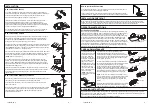
INSTALLATION
How to Install the Showerhead
Turn the diverter handle(21), run hot and cold water for about one minute to remove
any debris before the showerhead(26) is installed.
Take out the washer(27) and install the restrictor(28) into the showerhead if needed,
reinstall the washer. Tighten the showerhead onto the tube kit outlet with strap wrench.
CARE AND MAINTENANCE
Ensure that all connections are tight. Ensure that the handle is in the off position. Turn on the drain and main water
supply, and check for leaks. Repair as needed. Remove the handspray. Run hot and cold water through the faucet for
about one minute to remove any debris. Check for leaks. Shut off the faucet, and reinstall the handspray.
INSTALLATION CHECKOUT
Verifications and Setting
Make sure that the water feeds of the faucet have reach their highest temperature by
letting the water run sufficiently. With the selector in position 37°C, the temperature of
the water coming out of the faucet must be within a range of 36°C and 38°C, as
measured by a thermometer. If this is not the case, the installer can adjust the setting.
Proceed with the setting as follows: Remove the handle plug. Untighten the screw
with the screwdriver, remove the handle kit. With the faucet on “cold” normal water
flow, slowly turn the temperature selector(always in the same direction) until water at
37°C is obtained. If the temperature goes over 38°C, go back to the “cold” setting and
set again. When the temperature is stabilized, without turning the cartridge spindle,
make sure the reference mark of the temperature handle aligned with the number 37.
Tighten the screw, put on the handle plug as shown.
OPERATION INSTRUCTIONS
CLEANING INSTRUCTIONS
All Finishes: Clean the finish with mild soap and warm water. Wipe entire surface completely dry with clean soft cloth.
Many cleaners may contain chemicals, such as ammonia, chlorine, toilet cleaner etc. which could adversely affect the
finish and are not recommended for cleaning.
Do not use abrasive cleaners or solvents on Kohler faucets and fittings.
2
Hot
Cold
1
6
7
12
8-2
14
6
7
12
8-1
14
13
16
15
10
11
9
How to Install the Handspray and Hose
Remove the guards on the outlet connectors of 500mm length hose(18). Connect
the outlet(17) to the connector(20) with the hose(18), and tighten.
Turn the diverter handle(21), run hot and cold water for about one minute to
remove any debris.
Remove the guards on the outlet connectors of 1500mm length hose(22). Tighten
one connector(22-1) of the hose to the connector(23). Put the restrictor(24) into
the handspray(25) inlet if needed. Tighten the handspray to another
connector(22-2) of the hose.
Number 37
Round laser mark
Spindle
The filters(29) protecting
the faucet device may get
obstructed and reduce
water flow. When this
happens, unscrew the
bushes(30, left thread) by
a wrench (12mm) and
take out the nuts(31),
filters(29) and the check
valves(32) after removing
the faucet. Clean the
filters by soaking them in
warm vinegar. Reinstall
them as the figure.
(
NOTE:
Check valves
should reinstall as original
orientation).
29
30
31
32
Notch
Stop pin
Fig.4
Fig.3
Stop pin
Notch
Fig.1
Fig.2
Cartridge
Nut
Stopper
Groove
Round mark
Fig.5
Very hard water can obstruct the filters on the
thermostatic cartridge and reduce the flow of water.
Please clean the cartridge as follows: Shut off the water
supply of the faucet and open the water flow handle, then
proceed to remove the cartridge. The cartridge is sense
organ, please be careful.
Mark sure the reference mark is aligned with number 37
before your action. Remove the handle kit(Fig.1), unscrew
the nut and stopper(Fig.2). Remove the cartridge
cautiously(Fig.2). Clean the thermostatic cartridge by
soaking it in warm vinegar. After cleaning, install the “stop
assembly” back to the cartridge, adjusting the stop pin into
the notch(Fig.3). Install the assembly cartridge and stop in
the body, adjusting the stop pin into the notch(Fig.4).
NOTE:
Do not turn the cartridge when reinstall it. If you
turned it without carefully, you should adjust it and be sure
that the round mark is correctly in line with the groove
(Fig.5), or readjust as per the steps of verification and
setting.
Install the temperature selector(without turning the spindle)
aligning the number 37 with the reference mark(Fig.1).
Tighten the handle with the screw. Put on the handle plug.
3
150mm
29mm
4
5
22
18
17
24
25
22-2
22-1
20
21
23
26
27
28


