


TP-6694
9/20
33
1.2.8
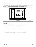
Communication Ports
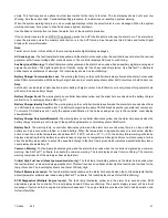
The main logic circuit board contains a single mini USB communication port for PC connections, see Figure 7. For Modbus
®
communication using RS-485, see the figure titled: Main Circuit Board Connectors (P21). Refer to the List of Related Materials
in the Introduction for corresponding SiteTech™ software and/or communication installation information.
Figure 7
Communication Port
1.2.9
Fuses
AC Circuit Fuses (TB5)
. Fuses are located inside the generator set control box. See Figure 8.
1.5-Amp (V7)
fuse protects L1 sensing input to interconnection circuit board.
1.5-Amp (V8)
fuse protects L2 sensing input to interconnection circuit board.
1.5-Amp (V9)
fuse protects L3 sensing input to interconnection circuit board.
DC Circuit Fuses
are located on the controller circuit board. See Figure 9.
1-Amp (F1)
auto-resettable, fuse protects the controller circuits.
1-Amp (F2)
auto-resettable fuse protects the controller circuits.
12-Amp (F3)
non-replaceable fuse protects the engine/starting circuitry and accessories.
Mini USB connection
FAULT
OFF/RESET
AUTO
RUN
ALARM SILENCE
/
LAMP TEST
GM65741-
Содержание APM402
Страница 6: ...6 TP 6694 9 20 ...
Страница 16: ...16 TP 6694 9 20 ...
Страница 42: ...42 TP 6694 9 20 ...
Страница 78: ...78 TP 6694 9 20 ...
Страница 112: ...112 TP 6694 9 20 ...
Страница 120: ...120 TP 6694 9 20 ...
Страница 124: ...124 TP 6694 9 20 Figure 54 20 150 kW Permanent Magnet Single Phase Alternators ADV 5875AB 1 ...
Страница 125: ...TP 6694 9 20 125 Figure 55 20 300 kW Permanent Magnet Alternators ADV 5875AB 2 ...
Страница 126: ...126 TP 6694 9 20 Figure 56 60 IMS 300 kW Wound Exciter Field 20 300 kW 600 V Perm Magnet Alternators ADV 5875AB 3 ...
Страница 127: ...TP 6694 9 20 127 Figure 57 300 kW and Larger Pilot Excited Permanent Magnet 4M 5M 7M 10M Alternators ADV 5875AB 4 ...
Страница 128: ...128 TP 6694 9 20 ...
Страница 131: ...TP 6694 9 20 131 Figure 61 Battery Charger to Controller Connections DEC 3000 Controller ...
Страница 153: ...TP 6694 9 20 153 Figure 90 Controller Wiring Connections GM78246G 1 ...
Страница 154: ...154 TP 6694 9 20 Figure 91 Controller Wiring Connections GM78246G 2 ...
Страница 171: ......


