


122
TP-6694
9/20
5.2 Voltage Reconnection Procedure
Note:
For Decision-Maker
®
3000 Controllers with software versions before 2.8, go to the next Section.
Press the generator set master control OFF/RESET button
1. Turn the controller pushbutton/rotary selector dial until it stops at the Volt Select menu. See Figure 53
Note:
If the Volt Select menu does not appear, the controller voltage selection feature was not activated using
SiteTech™
software.
Figure 53
Volt Select Menu
2. Press the selector dial and the voltage selection option (second line on the display) will start to flash.
3. Turn the selector dial clockwise or counterclockwise until the desired voltage selection option appears.
4. Press the selector dial. The second line on the display will stop flashing and the new voltage will appear.
5. Rotate the generator set voltage selector switch (if equipped) to match the desired voltage shown on the controller
display. Skip steps 7-9 and go to step 10.
If the generator set does not have a voltage selection switch, continue to step 7
6. Disconnect the generator set engine starting battery, negative (-) lead first. Disconnect power to the battery charger
(if equipped).
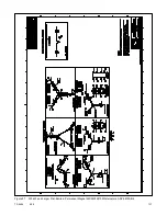
7. Use the figure titled: 20-150 kW Permanent Magnet Single-Phase Alternators, ADV-5875U-1, figure titled: 20-300 kW
Permanent Magnet Alternators, ADV-5875U-2, or figure titled: 300 kW and Larger Pilot-Excited, Permanent Magnet
4M/5M/7M/10M Alternators, ADV-5875U-4 to determine the generator set voltage configuration. Note the original
voltage and reconnect as needed. Route leads through current transformers (CTs) and connect them according to the
diagram for the desired phase and voltage.
Note:
Position current transformers CT1, CT2, and CT3 with the dot or HI side CT marking toward the generator set.
8. Reconnect the battery, negative lead last.
9. Press the generator set master control RUN button to start the generator set. Check the digital display for correct
voltages using the section titled: Generator Metering (and Calibration).
10. Press the generator set master control OFF/RESET button to stop the generator set after completing the voltage
adjustments.
Volt Select:
-->
###/### V # Ph
TP-6649-2
120/240 V 1 Ph
120/208 V 3 Ph
13/240 V 1 Ph
277/480 V 1 Ph
120/240 V 1 Ph
Содержание APM402
Страница 6: ...6 TP 6694 9 20 ...
Страница 16: ...16 TP 6694 9 20 ...
Страница 42: ...42 TP 6694 9 20 ...
Страница 78: ...78 TP 6694 9 20 ...
Страница 112: ...112 TP 6694 9 20 ...
Страница 120: ...120 TP 6694 9 20 ...
Страница 124: ...124 TP 6694 9 20 Figure 54 20 150 kW Permanent Magnet Single Phase Alternators ADV 5875AB 1 ...
Страница 125: ...TP 6694 9 20 125 Figure 55 20 300 kW Permanent Magnet Alternators ADV 5875AB 2 ...
Страница 126: ...126 TP 6694 9 20 Figure 56 60 IMS 300 kW Wound Exciter Field 20 300 kW 600 V Perm Magnet Alternators ADV 5875AB 3 ...
Страница 127: ...TP 6694 9 20 127 Figure 57 300 kW and Larger Pilot Excited Permanent Magnet 4M 5M 7M 10M Alternators ADV 5875AB 4 ...
Страница 128: ...128 TP 6694 9 20 ...
Страница 131: ...TP 6694 9 20 131 Figure 61 Battery Charger to Controller Connections DEC 3000 Controller ...
Страница 153: ...TP 6694 9 20 153 Figure 90 Controller Wiring Connections GM78246G 1 ...
Страница 154: ...154 TP 6694 9 20 Figure 91 Controller Wiring Connections GM78246G 2 ...
Страница 171: ......


