


TP-6073 4/06
77
Appendix
Appendix B Common Hardware Application Guidelines
Use the information below and on the following pages to
identify proper fastening techniques when no specific
reference for reassembly is made.
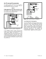
Bolt/Screw Length
: When bolt/screw length is not given,
use Figure 1 as a guide. As a general rule, a minimum
length of one thread beyond the nut and a maximum
length of 1/2 the bolt/screw diameter beyond the nut is
the preferred method.
Washers and Nuts
: Use split lock washers as a bolt
locking device where specified. Use SAE flat washers
with whiz nuts, spiralock nuts, or standard nuts and
preloading (torque) of the bolt in all other applications.
See General Torque Specifications and other torque
specifications in the service literature.
G-585
Preferred Nut/Bolt Clearance
Unacceptable Nut/Bolt Clearance
1
2
3
1. 1/2 of bolt diameter
2. Minimum 1 full thread beyond top of nut
3. Below top of nut
Figure 1
Acceptable Bolt Lengths
Steps for common hardware application
1. Determine entry hole type: round or slotted.
2. Determine exit hole type: fixed female thread (weld
nut), round, or slotted.
For round and slotted exit holes, determine if
hardware is greater than 1/2 inch in diameter, or
1/2 inch in diameter or less.
Hardware that is
greater than 1/2 inch
in diameter takes a standard
nut and SAE washer. Hardware
1/2 inch or less
in
diameter can take a properly torqued whiz nut or
spiralock nut. See the diagram below.
3. Follow these SAE washer rules after determining
exit hole type:
a. Always use a washer between hardware and a
slot.
b. Always use a washer under a nut (see 2 above
for exception).
c. Use a washer under a bolt when the female
thread is fixed (weld nut).
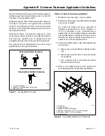
4. Refer to the diagram below, which depicts the
preceding hardware configuration possibilities.
G-585
1
2
3
4
5
6
1. Cap screw
2. Entry hole types
3. Standard nut and SAE washer
4. Whiz nut or spiralock: up to 1/2 in. dia. hardware
5. Weld nuts: above 1/2 in. dia. hardware
6. Exit hole types
Figure 2
Acceptable Hardware Combinations
Содержание 10EOR
Страница 10: ...10 Safety Precautions and Instructions TP 6073 4 06 Notes...
Страница 12: ...TP 6073 4 06 12 Service Assistance Notes...
Страница 22: ...TP 6073 4 06 22 Section 3 Intake and Exhaust System Notes...
Страница 26: ...TP 6073 4 06 26 Section 4 Fuel System Notes...
Страница 30: ...TP 6073 4 06 30 Section 5 Cooling System Notes...
Страница 38: ...TP 6073 4 06 38 Section 6 Controller Troubleshooting Notes...
Страница 54: ...TP 6073 4 06 54 Section 8 Component Troubleshooting Notes...
Страница 60: ...TP 6073 4 06 60 Section 9 Generator Disassembly Reassembly Notes...
Страница 82: ...TP 6073 4 06 82...
Страница 83: ...TP 6073 4 06 83...


