Chapter 1 Prior to installation
MDC-7000/7900 Series
1-2
0092669002-07
1.4.1 Antenna Scanner unit
(1) Blind sectors shall be kept to a minimum, and shall not be placed in an arc of the horizon from the
right ahead direction to 22.5° abaft the beam and especially shall avoid the right ahead direction
(relative bearing 000°). The installation of the antenna shall be in such a manner that the
performance of the radar system is not substantially degraded. The antenna shall be mounted
clear of any structure that may cause signal reflections, including other antenna and deck structure
or cargo. In addition, the height of the antenna shall take account of target detection performance
relating to range of first detection and target visibility in sea clutter.
(2) Keep the surface of the Antenna-Scanner unit platform horizontal as much as possible.
(3) The Antenna-Scanner unit should be installed in front of large objects or exhaust stack to prevent a
blind sector or the effects on the antenna by engine exhaust soot.
(4) Keep sufficient maintenance area.
(5) Keep safety distance from magnetic compass.
=15m
40m
16°
Antenna
height
Minimum range
Navigation buoy with
corner reflector
When the antenna height
rises, Minimum Range
becomes long.
Minimum
range(m)
Antenna
height(m)
=(
This area is prohibited from
setting up of the structure.
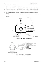
Figure 1.1 Vertical chart of recommended antenna installation position.
BOW
22.5°
22.5°
This area is prohibited from setting
up of the structure.
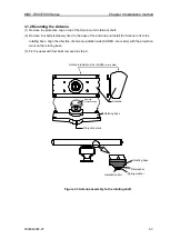
Figure 1.2 Horizontal chart of recommended antenna installation position.
Содержание MDC-7006
Страница 1: ......
Страница 2: ......
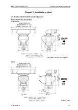
Страница 44: ...Chapter 3 installation method MDC 7000 7900 Series 3 24 0092669002 07 Unit mm inch MRM 108 ...
Страница 96: ... This page intentionally left blank ...
Страница 134: ... This page intentionally left blank ...
Страница 155: ...0092669002 07 A 1 INTER CONNECTION DIAGRAM RB807 ...
Страница 156: ...A 2 0092669002 07 INTER CONNECTION DIAGRAM RB808 ...
Страница 157: ...0092669002 07 A 3 INTER CONNECTION DIAGRAM RB809 ...
Страница 158: ...A 4 0092669002 07 INTER CONNECTION DIAGRAM MRD 108 MRO 108 ...
Страница 159: ...0092669002 07 A 5 INTER CONNECTION DIAGRAM MRM 108 MRO 108 ...
Страница 160: ......


