Installation
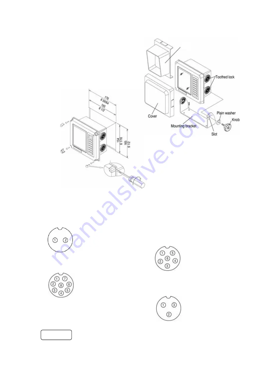
Mounting display unit
Hood
The bracket with slot facing toward you should be
installed
on a flat and solid surface for maximum
stability.
Overhead mounting is also possible.
Position the bracket, mark and drill four (4) holes.
Securely screw it.
Place the display in the bracket and secure it to the
bracket
applying two bracket knobs and washers.
Connector plug pin assignment
Four connectors are mounted on the rear panel including the power connector.
Refer to Name page 2.
The functions and pin assignment viewed from cable side are specified below.
10.8-31.2VDC
Power Input (10.8 to 31.2VDC)
1. LINE+:
Red
wire
2. LINE-:
Black
wire
SER DATA
Serial data(Navigator)
1. SHIELD
2. SER.OUT(SIG)
3. SER.OUT(RTN)
4. SER.IN(SIG)
5. SER.IN(RTN)
6. NC(No
connector)
TRI
TRI (Transducer with TEMP/SPEED sensor)
1. SPD.PULSE
2. SPD.Vcc
3. TD1
4. TD
SHIELD
5. TD2
6. TEMP
Vcc
7. TEMP
SIG
8. SPD.GND
STD
STD(Standard transducer)
1. TD1
2. TD
SHILD
3. TD2
CAUTION
Be careful with the installation of transducer pins 3 and 5 in
TRI
(triducer) and pin 1 and 3 in
STD
(standard transducer) from other pins as
high voltage
is applied to these pins.
0093132312/0093132314 21


