background image


© Eastman Kodak Company, 2006

Confidential

Restricted Information

{ServiceManual}{Production}{KodakServiceSupport}{ExternalAndInternal}

Publication No. SM1399-1

19JUN06

SERVICE MANUAL

for the

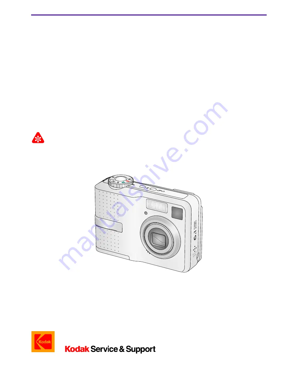
Kodak EasyShare C643 ZOOM DIGITAL CAMERA

Service Code: 1399

and the

Kodak EasyShare C603 ZOOM DIGITAL CAMERA

Service Code: 1417

Important

Qualified service personnel must repair this equipment.

Содержание 1399

Страница 1: ...on KodakServiceSupport ExternalAndInternal Publication No SM1399 1 19JUN06 SERVICE MANUAL for the Kodak EasyShare C643 ZOOM DIGITAL CAMERA Service Code 1399 and the Kodak EasyShare C603 ZOOM DIGITAL CAMERA Service Code 1417 Important Qualified service personnel must repair this equipment ...

Страница 2: ...s for the CAMERA DOCK 6 Reference Table for New CAMERAS 7 Reference Table for Adjustment Procedures 8 Visual Index 9 Equipment Parts 10 COVER AYs 10 MONITOR LCD 12 LENS AY AND MCU BOARD POWER BOARD AND FRAME AY SHUTTER BOARD 13 Alphabetical Index 15 Diagnostics 16 Error Codes 16 Troubleshooting 17 Diagnostic Tests 22 Checkout Procedures 30 Adjustments 36 MCU BOARD LENS AY Shutter Delay 36 MASTER C...

Страница 3: ...1399 1 19JUN06 3 Diagrams 77 Block 77 System Overview 77 Schematics 78 MCU BOARD 78 POWER BOARD 87 SHUTTER BOARD 90 Component Locator 91 MCU BOARD 91 POWER BOARD 93 SHUTTER BOARD 95 Publication History 96 ...

Страница 4: ... TL 5412 TIP soldering iron standard ST1 optional TL 5413 TIP soldering iron single flat ST5 optional TL 5414 TIP soldering iron conical ST7 optional TL 5415 SOLDER REMOVAL TOOL Region Provided FLASH CAPACITOR DISCHARGE TOOL resistor minimum 6 8 kΩ TL 5337 DIGITAL VOLTMETER TL 4114 DC POWER SUPPLY 0 12 V 5 0 A with clip leads ez or alligator Region Provided AIR HOSE optional Region Provided Kodak ...

Страница 5: ...NT TOOL battery simulator TL 5637 Kodak OXY ALKALINE DIGITAL CAMERA BATTERY AA 2 pack 1 5 V non rechargeable 892 2338 Kodak OXY ALKALINE DIGITAL CAMERA BATTERY AA 4 pack 1 5 V non rechargeable 889 3992 Kodak LITHIUM DIGITAL CAMERA BATTERY CRV3 3 0 V non rechargeable 888 2938 Kodak Ni MH RECHARGEABLE DIGITAL CAMERA BATTERY KAA2HR 2 4 V 2100 mAh 815 6572 Kodak Ni MH RECHARGEABLE DIGITAL CAMERA BATTE...

Страница 6: ... C643 ZOOM DIGITAL CAMERA or the C603 ZOOM DIGITAL CAMERA to the Kodak EasyShare CAMERA DOCK 6000 The Kodak EasyShare C643 and C603 ZOOM DIGITAL CAMERAS are compatible with Kodak EasyShare CAMERA DOCK SERIES 3 other 26 PIN DOCKS CUSTOM DOCK INSERT CAMERA DOCK 6000 CUSTOM DOCK INSERT DOCK SERIES 3 DOCK ADAPTER KIT D 22 P252_0075BA Figure 1 Figure 2 CAMERA ...

Страница 7: ...nd the Middle East English French German 859 4129 167 4399 Europe Africa and the Middle East Italian Spanish Portuguese 393 6903 393 6978 Europe Africa and the Middle East Nordic Swedish Danish Finnish 393 6911 393 6986 Europe Africa and the Middle East Emerging English Russian Turkish Polish 393 6929 393 6994 Greater China and Taiwan English Chinese simplified traditional Korean 100 0587 187 4775...

Страница 8: ... Support bulk class B English SP 864 4676 SP 192 7417 Kodak Service Support retail class B English SP 866 5580 SP 116 4789 Component Procedure LENS AY AND MCU BOARD MCU BOARD LENS AY Shutter Delay on Page 36 CCD AWB ISO DBP on Page 40 Region Language Catalog No for C643 Catalog No for C603 ...

Страница 9: ...Parts List SM1399 1 19JUN06 9 Visual Index Item Description 1 COVER AYs on Page 10 2 MONITOR LCD on Page 12 3 LENS AY AND MCU BOARD POWER BOARD AND FRAME AY SHUTTER BOARD on Page 13 P273_1000DC 3 1 2 1 P273_1000DCA ...

Страница 10: ...19JUN06 SM1399 1 Equipment Parts Caution Before removing the BACK COVER AY you must remove if installed MEMORY CARD BATTERY Figure 1 COVER AYs P273_1001DC 1 5 6 4 2 3 7 8 1 1 9 P273_1001DCA 1 1 1 2 3 4 5 6 7 8 9 1 1 1 1 ...

Страница 11: ...1 4 3F9423 CARD DOOR AY C643 1 1 3F9466 CARD DOOR AY C603 1 1 5 3F9424 SHAFT card door 1 1 6 3F9425 SPRING card door 1 1 7 3F9421 SHAFT battery door 1 1 8 3F9422 SPRING battery door 1 1 9 3F9419 BATTERY DOOR C643 1 1 3F9465 BATTERY DOOR C603 1 1 3F9618 PLATE data C643 1 1 Not visible in the graphic 3F9619 PLATE data C603 1 1 Not visible in the graphic 3F6387 STRAP wrist 1 1 Not visible in the grap...

Страница 12: ...2 19JUN06 SM1399 1 Figure 2 MONITOR LCD Figure 2 MONITOR LCD Item Part No Description Quantity Notes 1 3F9413 MONITOR LCD 2 1 See MONITOR LCD on Page 46 for special replacement instructions P273_1002HC P273_1002HCA 1 1 ...

Страница 13: ...e SOLDER from the SOLDER JOINTS do a discharge of the CAPACITOR at the CONTACTS see Step 1 in To Remove for the POWER BOARD AND FRAME AY on Page 44 Figure 3 LENS AY AND MCU BOARD POWER BOARD AND FRAME AY SHUTTER BOARD P273_1003HC 10 6 6 P273_1003HCA 6 6 7 4 3 2 1 5 8 9 6 11 12 1 2 3 4 5 6 6 6 7 6 8 9 10 6 11 12 ...

Страница 14: ... replacement instructions 4 3F9418 BOARD shutter 3 1 5 3F9426 ESD PLATE monitor LCD 3 1 6 3F6412 SCREW tapping 1 7 x 3 0 black3 4 7 3F9416 BOARD mcu 3 1 See MCU BOARD on Page 47 for details on where the colored WIRES are soldered to the MCU BOARD 8 3F9420 LENS AY 3 1 9 3F9443 ESD PLATE speaker 3 1 10 HOOK A 3 1 Release the LENS AY AND MCU BOARD from the HOOK A 11 HOOK B 3 1 Release the SHUTTER BOA...

Страница 15: ...VER front C643 1 3F9428 CUSTOM DOCK INSERT 1 3F9426 ESD PLATE monitor LCD 3 3F9443 ESD PLATE speaker 3 3F6204 FUSE 1 25 A F3 3 3F6205 FUSE 2 5 A F1 F2 3 HOOK A 3 HOOK B 3 3F9583 LENS AND MCU BOARD AY 3 3F9420 LENS AY 3 3F9413 MONITOR LCD 2 3F9619 PLATE data C603 1 3F9618 PLATE data C643 1 3F9417 POWER BOARD AND FRAME AY 3 3F6412 SCREW tapping 1 7 x 3 0 black 3 3F6374 SCREW tapping 1 7 x 4 0 nickel...

Страница 16: ... BOARD 3 Install a new LENS AY Description Recommended Action An error occurred when the LENS was extended after energizing the CAMERA 1 Check the FPC CABLE from the MOTOR to the CONNECTOR J3 on the MCU BOARD 2 Install a new MCU BOARD 3 Install a new LENS AY Description Recommended Action An error occurred when the STEP MOTOR was reset after energizing the CAMERA 1 Check the FPC CABLE from the MOT...

Страница 17: ...OTOR to the CONNECTOR J3 on the MCU BOARD 2 Install a new MCU BOARD 3 Install a new LENS AY Description Recommended Action An error occurred when the LENS was retracting 1 Check the FPC CABLE from the MOTOR to the CONNECTOR J3 on the MCU BOARD 2 Install a new MCU BOARD 3 Install a new LENS AY Description Recommended Action An error occurred when the LENS was extending 1 Check the FPC CABLE from th...

Страница 18: ... LCD new MCU BOARD LENS AY Malfunction of pixels occurs on the MONITOR LCD Install a new MONITOR LCD The image on the MONITOR LCD is not in focus Install a new MONITOR LCD Horizontal or vertical lines display on the MONITOR LCD 1 Check FPC from the MONITOR LCD to CONNECTOR J1 on the MCU BOARD MCU BOARD LENS AY has no damage 2 Install new MONITOR LCD MCU BOARD LENS AY Description Recommended Action...

Страница 19: ...CARD 1 Use a new MEMORY CARD 2 Check IMAGE STORAGE option is set to AUTO SOCKET of the MEMORY CARD on the MCU BOARD LENS AY has no damage 3 Do Upgrading the Firmware Using the Internal Memory on Page 75 Images are not stored on the MEMORY CARD 1 Use a new MEMORY CARD 2 Check position of the WRITE PROTECT SWITCH on the SD CARD IMAGE STORAGE option is set to AUTO SOCKET of the MEMORY CARD on the MCU...

Страница 20: ...MODE DIAL BOARD POWER BOARD MCU BOARD LENS AY The CAMERA with no BATTERY does not operate on the CAMERA DOCK 1 Check the DOCK CONNECTOR on the CAMERA 2 Install a new MCU BOARD LENS AY Description Recommended Action The images are black 1 Check BOARD TO BOARD CONNECTOR J1 on the MCU BOARD LENS AY to J3 on the POWER BOARD FPC any sound from the SHUTTER 2 Install a new MCU BOARD LENS AY The image is ...

Страница 21: ...MCU BOARD LENS AY Description Recommended Action One or more do not operate correctly menu BUTTON FLASH BUTTON share BUTTON delete BUTTON review BUTTON 4 WAY BUTTON OK BUTTON 1 Check for damage to BUTTONS inside the BACK COVER AY 2 Install a new BACK COVER AY MCU BOARD LENS AY The SHUTTER BUTTON does not operate correctly 1 Check the connection of the SHUTTER BOARD to the MCU BOARD LENS AY 2 Insta...

Страница 22: ... DIGITAL MULTIMETER to the BATTERY VOLTAGE ADJUSTMENT TOOL 7 Check that the CAMERA is de energized 8 Install the CAMERA on the BATTERY VOLTAGE ADJUSTMENT TOOL 9 Energize the CAMERA 10 Check that the current is within the limits 11 Is the current within the limits During the first 10 seconds After 10 seconds 1 mA 80 mA 0 5 mA 20 mA Yes No De energize the CAMERA 1 Install a new POWER BOARD AND FRAME...

Страница 23: ...OBE actuates image displays correctly low Battery icon displays 10 Press review BUTTON T BUTTON continually to a magnification to 8X 11 Check the MONITOR for image quality 12 Do any of the following errors occur red VIEWFINDER LED blinks Battery icon blinks error message Batteries are too low for live view displays Wire Color From the DIGITAL MULTIMETER To the BATTERY VOLTAGE ADJUSTMENT TOOL Red 2...

Страница 24: ...test is completed de energize the CAMERA 8 Remove the MEMORY CARD Test Check F W n nnnn version of the firmware MCU n nnnn version of the MCU RGB Level Checking quality of the 6 colors Gray Level Checking quality of the 6 gray areas LEDs On Off testing green LED on the front of the CAMERA illuminates red and green LEDs on the back of the CAMERA illuminate LCD On Off testing MONITOR LCD blinks Stro...

Страница 25: ...tics SM1399 1 19JUN06 25 Checking for Uniform Flash Important A dark room or the GEN 3 CUSTOM TEST FIXTURE can be used The distance is measured from the surface of the TARGET to the front surface of the CAMERA ...

Страница 26: ... TEST FIXTURE with VERTICAL MEASURE TUBE J for T1 HORIZONTAL MEASURE TUBE H and K for T4 X axis to 1344 Y axis to 1072 d Place 18 gray TARGET in the TARGET FRAME CAMERA DOCK on the CAMERA NEST CAMERA on the CAMERA DOCK e Press and hold review BUTTON T TELE BUTTON f Rotate the MODE DIAL to Auto g Release the BUTTONS h Press the TRANSFER BUTTON on the CAMERA DOCK i Check that the MONITOR LCD de ener...

Страница 27: ...sh Uniformity window 6 Click Yes 7 Continue with Checking Wide IQ Chart w o Flash on Page 28 Green Red X The test was successful Continue with Step 5 A failure occurred De energize the CAMERA Do Checking for Uniform Flash on Page 25 again If the failure occurs again check the hardware ...

Страница 28: ...SERVICE MANUAL 28 19JUN06 SM1399 1 Checking Wide IQ Chart w o Flash 1 Select Wide IQ Chart w o Flash 2 Click OK 3 Click Yes 4 Continue with Checking Wide IQ Chart with Flash on Page 29 ...

Страница 29: ...nostics SM1399 1 19JUN06 29 Checking Wide IQ Chart with Flash 1 Select Wide IQ Chart with Flash 2 Click OK 3 Click Yes 4 Close Menu for service window VISTA for SERVICE Kodak window 5 De energize the CAMERA ...

Страница 30: ...n the CAMERA DOCK illuminates green 9 Remove CAMERA from the CAMERA DOCK CRV3 BATTERY from CAMERA 10 Install Ni MH BATTERY in the CAMERA CAMERA on the CAMERA DOCK 11 Check one or more of the LEDs for the BATTERY on the CAMERA DOCK illuminate green STATUS LED on the CAMERA DOCK illuminates green 12 Remove the CAMERA from the CAMERA DOCK 13 Energize the CAMERA 14 Check that the CAMERA energizes 15 D...

Страница 31: ...Press 4 WAY BUTTON up or down to move through the menu OK BUTTON to select an option OK BUTTON again to return to the screen before menu BUTTON to quit 4 Press menu BUTTON SHUTTER BUTTON 5 Check CAMERA quits the menu image is captured image displays on the MONITOR LCD review share 1 Press the review BUTTON 2 Check that the MONITOR LCD illuminates 3 Press 4 WAY BUTTON left and right to display imag...

Страница 32: ...changes to Auto Flash Fill Flash Red Eye Flash Off 4 Press the SHUTTER BUTTON 5 Check image is captured without the FLASH image displays on the MONITOR LCD SHUTTER 1 Press the SHUTTER BUTTON to capture an image 2 Check green LED blinks once before the CAMERA captures the image image appears on the MONITOR LCD green LED blinks when the CAMERA stores the image BUTTON SWITCH Do ...

Страница 33: ...it the delete screen review BUTTON to return to the Auto mode 5 Press review BUTTON delete BUTTON SHUTTER BUTTON to capture an image 6 Check CAMERA quits the delete screen image is captured image displays on the MONITOR LCD 7 Immediately press the delete BUTTON 8 Use the 4 WAY BUTTON to select YES 9 Press OK BUTTON review BUTTON 10 Use the 4 WAY BUTTON to check that the image is deleted 11 Press t...

Страница 34: ...ER BUTTON 5 Check that the MONITOR LCD displays Press OK to Play or Pause 6 Press the OK BUTTON 7 Check that the video begins to play back 8 Press the OK BUTTON 9 Check that the video stops 10 Press the delete BUTTON 11 Check that the MONITOR LCD displays VIDEO in the list of options 12 Press delete BUTTON to quit review BUTTON 13 Check that the MONITOR LCD illuminates in Liveview mode Favorites 1...

Страница 35: ...NECTOR on the MCU BOARD is operating correctly Checking the Accessories 1 Disconnect the USB CABLE from the CAMERA 2 Connect the VIDEO MONITOR to the CAMERA with the VIDEO CABLE 3 If you are not using the internal memory insert a MEMORY CARD with image files into the CAMERA 4 Energize the CAMERA 5 Press the review BUTTON 6 Check that the MONITOR LCD de energizes and the image displays on the VIDEO...

Страница 36: ...RY with a full charge into the C643 CAMERA C643_C603 Shutter_Delay MEMORY CARD into the CAMERA 3 Set the LIGHT BOX to LV15 4 Place the center of the LENS against the screen of the LIGHT BOX 5 Rotate the MODE DIAL to AUTO to execute the test 6 If the MONITOR LCD displays Date and time have been reset select CANCEL 7 When the test is completed check that the MONITOR LCD displays Shutter Calibrate OK...

Страница 37: ...Adjustments SM1399 1 19JUN06 37 Postrequisites None ...

Страница 38: ... If you are doing a calibration of the C603 CAMERA use the correct MASTER CAMERA and MEMORY CARDS made for that CAMERA in the procedure in Step 1 1 Do Preparing the C643_C603 Master Camera MEMORY CARD on Page 68 2 Insert new BATTERY with a full charge into a MASTER CAMERA for the C643 CAMERA C643_C603 Master Camera MEMORY CARD into the CAMERA Purpose To set the values for Automatic White Balance I...

Страница 39: ...en the test is completed check that the MONITOR LCD displays Small LB OK 13 De energize the CAMERA 14 Remove the MEMORY CARD 15 Check that the following 2 additional files were written on the MEMORY CARD CamerID_ref fig Small_LAMP fig Note These 6 files are necessary before you do Preparing the C643_C603 AWB_ISO_DBP MEMORY CARD on Page 65 16 If the MONITOR LCD displays a failure message do the cor...

Страница 40: ...43_C603 AWB_ISO_DBP MEMORY CARD on Page 65 2 Make a copy of the following files from the C643_C603 Master Camera MEMORY CARD BIG_LAMP fig BoxID_ref fig CameraID_ref fig K_RESULT txt CamerID_ref fig Small_LAMP fig 3 Place these 6 files in the folder Batch on the C643_C603 AWB_ISO_DBP MEMORY CARD 4 Insert new BATTERY with a full charge into a C643 CAMERA C643_C603 AWB_ISO_DBP MEMORY CARD into the CA...

Страница 41: ...e CAMERA 12 If the MONITOR LCD displays the failure message ISO Cal Fail open the file K_RESULT TXT to obtain the type of failure do the necessary correction Postrequisites None Failure Cause Correction W O Shutter K The calibration of the SHUTTER was not correct Do 1 MCU BOARD LENS AY Shutter Delay on Page 36 2 CCD AWB ISO DBP on Page 40 again Memory Fail An occasional failure occurred during a t...

Страница 42: ... 67 2 Make a copy of the following files from the C643_C603 Master Camera MEMORY CARD BIG_LAMP fig BoxID_ref fig CameraID_ref fig K_RESULT txt CamerID_ref fig Small_LAMP fig 3 Place these 6 files in the folder Batch on the C643_C603 EFA MEMORY CARD 4 Insert AC ADAPTER in the CAMERA C643_C603 EFA MEMORY CARD into the CAMERA 5 Place the CAMERA on the CAMERA HOLDER in the INFINITY COLLIMATOR 6 Rotate...

Страница 43: ...e failure message NG 14 Capture some images at a variation of zoom positions of the LENS 15 Review the images on the MONITOR LCD 16 Check that the images are not too dark or too light 17 Press the T BUTTON to increase the magnification of the images to the maximum 18 Check that the images on the MONITOR LCD are in focus Postrequisites None Yes No a Install a new LENS AY AND MCU BOARD b Do Step 4 S...

Страница 44: ...rmation POWER BOARD AND FRAME AY Prerequisites None To Remove Caution To prevent injury you must do a discharge of the CAPACITOR 1 Before removing the POWER BOARD do a discharge of the CAPACITOR across the CONTACTS on the MCU BOARD 2 See LENS AY AND MCU BOARD POWER BOARD AND FRAME AY SHUTTER BOARD on Page 13 for the parts diagram ...

Страница 45: ...SISTOR R13 from the new replacement POWER BOARD AND FRAME AY Note See POWER BOARD 2 of 2 on Page 94 to locate the RESISTOR R13 4 Discard the RESISTOR R13 5 Remove the RESISTOR R13 from the old POWER BOARD AND FRAME AY 6 Install RESISTOR R13 on the new POWER BOARD AND FRAME AY new POWER BOARD AND FRAME AY 7 Assemble the CAMERA Postrequisites None CAMERA Beginning Serial Number C643 KCGFN61713506 C6...

Страница 46: ...ning Serial Number 3 Remove MONITOR LCD POWER BOARD AND FRAME AY Important See the replacement procedure for the POWER BOARD AND FRAME AY on Page 44 4 Install a new POWER BOARD AND FRAME AY MONITOR LCD 5 Assemble the CAMERA 6 Do Preparing the C643_C603 Monitor LCD MEMORY CARD on Page 69 7 Insert the C643_C603 Monitor LCD MEMORY CARD in the CAMERA 8 Energize the CAMERA 9 Check that the MONITOR LCD ...

Страница 47: ...CU BOARD POWER BOARD AND FRAME AY SHUTTER BOARD on Page 13 for the parts diagram To Install Important You must install the large red and black wires on the right 1 Solder each WIRE at the correct CONTACT on the MCU BOARD Postrequisites None CONTACT Size of WIRE Color of WIRE G small green W small white R small red small black B small blue Y small yellow large red large black GW R B Y P273_1006BC M...

Страница 48: ...artner site download the software and firmware files from Kodak EasyShare C643_C603_ ZOOM DIGITAL CAMERA_Software_and_Firmware 2 Right click the C643_C603_Software_Firmware zip file 3 Select WinZip Extract to here 4 Open the folder C643_C603_Software_Firmware 5 Open the folder Service_Software 6 Open the folder Vista for Service V4 1 0 7 ...

Страница 49: ...Additional Service Procedures SM1399 1 19JUN06 49 7 Check for the 10 files 8 Click Back 2 times 9 Open the folder Firmware_and_Scripts_C643_C603 10 Check for the 2 folders 11 Open the folder Batch Files ...

Страница 50: ...SERVICE MANUAL 50 19JUN06 SM1399 1 12 Check for 6 folders 13 Click Back 14 Open the folder Firmware 15 Check for the firmware file ...

Страница 51: ...stalling the Altek Vista SERVICE SOFTWARE on the Computer Important Microsoft Windows XP OPERATING SYSTEM is necessary for the correct operation of the SERVICE SOFTWARE 1 Open the folder Vista for Service 2 Open the folder Setup 3 Double click Setup exe ...

Страница 52: ...SERVICE MANUAL 52 19JUN06 SM1399 1 4 Wait until this window is complete the next window displays 5 Click Next ...

Страница 53: ...Additional Service Procedures SM1399 1 19JUN06 53 6 After selecting a folder click Next 7 Click Yes ...

Страница 54: ...ERA to the computer with the USB CABLE 10 Energize the CAMERA 11 Check that the Kodak EasyShare SOFTWARE detects the CAMERA 12 Click Cancel at the Transfer window Exit 13 At the lower right edge of the computer screen right click on the Kodak icon 14 Select Shut Down Kodak EasyShare software 15 Select Start Settings Control Panel ...

Страница 55: ...Additional Service Procedures SM1399 1 19JUN06 55 16 Double click System 17 At the System Properties window select the Hardware tab 18 Click Device Manager ...

Страница 56: ...SERVICE MANUAL 56 19JUN06 SM1399 1 19 Double click Imaging devices KODAK Digital Camera 20 Click Update Driver ...

Страница 57: ...Additional Service Procedures SM1399 1 19JUN06 57 21 Select Install from a list or specific location Advanced 22 Click Next 23 Select Don t search I will choose the driver to install 24 Click Next ...

Страница 58: ...SERVICE MANUAL 58 19JUN06 SM1399 1 25 Select Kodak Easy Share C643 USD 26 Click Next 27 Click Continue Anyway ...

Страница 59: ... the CAMERA 31 Remove the USB CABLE from the CAMERA 32 Double click the Vista for Service icon 33 To energize the CAMERA press and hold delete BUTTON T TELE BUTTON rotate MODE DIAL to AUTO 34 Install the USB CABLE to the CAMERA 35 Continue with Doing the Configuration of the SERVICE SOFTWARE on Page 60 ...

Страница 60: ...ANUAL 60 19JUN06 SM1399 1 Doing the Configuration of the SERVICE SOFTWARE Important You must do this procedure only once 1 Double click the Vista for Service icon 2 Click OK 3 Select Settings Password 4 Click OK ...

Страница 61: ... SM1399 1 19JUN06 61 5 Select Settings Configuration 6 Check that the information in the fields on this screen match the graphic Note If the information is not the same you must enter the information to match the graphic 7 Click OK ...

Страница 62: ... SM1399 1 8 Select Settings Specifications 9 Check that the path for the file kodak spe is C Program Files Altek Corp Vista for Service Kodak spe 10 Click OK 11 De energize the CAMERA 12 Disconnect the USB CABLE from the CAMERA ...

Страница 63: ... Click OK 4 At the same time press and hold review BUTTON T TELE BUTTON 5 Rotate the MODE DIAL to AUTO to energize the CAMERA 6 Check that the green LED next to the VIEWFINDER on the CAMERA blinks 7 Click the Take icon 8 Click Yes 9 If no errors display de energize the CAMERA disconnect the USB CABLE from the CAMERA continue with Checking for Uniform Flash on Page 25 ...

Страница 64: ...the SERVICE SOFTWARE Click OK Do Checking the Connection to the SERVICE SOFTWARE on Page 63 again Check CAMERA is energized connections for the USB CABLE connections for the AC ADAPTER connections the CAMERA DOCK see Installing the Altek Vista SERVICE SOFTWARE on the Computer on Page 51 ...

Страница 65: ...ant You will need 6 blank MEMORY CARDS The prepared MEMORY CARDS can be used for either EasyShare C643 ZOOM DIGITAL CAMERA EasyShare C603 ZOOM DIGITAL CAMERA Preparing the C643_C603 AWB_ISO_DBP MEMORY CARD 1 Open the folders Firmware_and_Scripts_C643_C603 Batch_Files 2 Open the folder AWB_ISO_DBP ...

Страница 66: ...SERVICE MANUAL 66 19JUN06 SM1399 1 3 Open the folder Batch 4 Check for 4 files 5 Click Back 6 Make a copy of the folder Batch to a blank MEMORY CARD 7 Label the MEMORY CARD C643_C603 AWB_ISO_DBP ...

Страница 67: ...M1399 1 19JUN06 67 Preparing the C643_C603 EFA MEMORY CARD 1 Open the folder EFA 2 Open the folder Batch 3 Check for 4 files 4 Click Back 5 Make a copy of the folder Batch to a blank MEMORY CARD 6 Label the MEMORY CARD C643_C603 EFA ...

Страница 68: ...paring the C643_C603 Master Camera MEMORY CARD 1 Open the folder Master Camera 2 Open the folder Batch 3 Check for 4 files 4 Click Back 5 Make a copy of the folder Batch to a blank MEMORY CARD 6 Label the MEMORY CARD C643_C603 Master Camera ...

Страница 69: ...N06 69 Preparing the C643_C603 Monitor LCD MEMORY CARD 1 Open the folder Monitor_LCD 2 Open the folder Batch 3 Check for 8 files 4 Click Back 5 Make a copy of the folder Batch to a blank MEMORY CARD 6 Label the MEMORY CARD C643_C603 Monitor LCD ...

Страница 70: ... 1 Preparing the C643_C603 Self_Test MEMORY CARD 1 Open the folder Self_Test 2 Open the folder Batch 3 Check for 3 files 4 Click Back 5 Make a copy of the folder Batch to a blank MEMORY CARD 6 Label the MEMORY CARD C643_C603 Self_Test ...

Страница 71: ... 71 Preparing the C643_C603 Shutter_Delay MEMORY CARD 1 Open the folder Shutter_Delay 2 Open the folder Batch 3 Check for 4 files 4 Click Back 5 Make a copy of the folder Batch to a blank MEMORY CARD 6 Label the MEMORY CARD C643_C603 Shutter_Delay ...

Страница 72: ...ust not touch the SCREEN of the LIGHT BOX 4 Place the MASTER CAMERA in front of the LIGHT BOX 5 Rotate the MODE DIAL to AUTO 6 If the Date and Time Setting mode displays on the MONITOR LCD select CANCEL 7 The calibration is complete when the MONITOR LCD displays Big LB OK Note The calibration results are stored on the C643_C603 Master Camera MEMORY CARD The files include BIG_LAMP fig BoxID_ref fig...

Страница 73: ...es 1 MCU BOARD LENS AY Shutter Delay on Page 36 2 Doing a Calibration of the Test Equipment on Page 72 again Memory Fail Software script failure Do the procedure Doing a Calibration of the Test Equipment on Page 72 again ISO Cal Fail Environment variation 1 Check the settings and environment variations 2 Do the procedure Doing a Calibration of the Test Equipment on Page 72 again ...

Страница 74: ...on the MEMORY CARD with the name System 8 Make a copy of the kc643nnn fw firmware file to the System folder on the MEMORY CARD 9 Change the file name to kc643 fw 10 Remove the MEMORY CARD from the CARD READER WRITER 11 Insert into the CAMERA BATTERY that has a full charge MEMORY CARD with the firmware file Important Do not rotate the MODE DIAL after the energizing 12 At the same time press the del...

Страница 75: ...name to kc643 fw 4 Connect a USB CABLE to CAMERA computer 5 Energize the CAMERA 6 Select kc643 fw file Edit Copy 7 Double click My Computer icon CAMERA icon Internal Memory folder 8 Select firmware file in the Internal Memory folder Edit Paste 9 De energize the CAMERA 10 Disconnect the USB CABLE from CAMERA computer 11 Energize the CAMERA 12 Select UPGRADE CONTINUE Note The upgrading of the firmwa...

Страница 76: ...firmware version 8 At the same time press 4 WAY BUTTON to the right delete BUTTON 9 Release the BUTTONS 10 Check that the MONITOR LCD displays HIDDEN MENU 11 Press the 4 WAY BUTTON up to TOTAL INFO 12 Press the OK BUTTON 13 Record the information for the COUNTERS in the FEEDBACK SOFTWARE 14 Press 4 WAY BUTTON left 2 times OK BUTTON menu BUTTON to exit COUNTERS on the CAMERA Description on the FEED...

Страница 77: ...H2 RG 10 bit L OK R 5 way button Take button Self timer LED Mode Dial USB conn Dock Share Dock det battery charge DOCK_PWR Battery Power sel F1 F2 Dock Batt DC DC convert 15 5V 8V 3 3V 1 5V 5VM feedback 12 5v FB4 I F SD1 ONM SD2 4 Flash light Flash Trigger circuit Strobe Cap Flash Charge Circuit 3 3V PWR Flash TRG Flash CHR Flash RDY Bat Type Det DC cont MCU 3 3V Flash TRG Bat Temp sensor I F Dock...

Страница 78: ...SERVICE MANUAL 78 19JUN06 SM1399 1 Schematics MCU BOARD 1 of 9 MCU BOARD 1 of 9 P273_0001KC_ ...

Страница 79: ...Diagrams SM1399 1 19JUN06 79 MCU BOARD 2 of 9 P273_0002KC_ MCU BOARD 2 of 9 ...

Страница 80: ...SERVICE MANUAL 80 19JUN06 SM1399 1 MCU BOARD 3 of 9 P273_0003KC_ MCU BOARD 3 of 9 ...

Страница 81: ...Diagrams SM1399 1 19JUN06 81 MCU BOARD 4 of 9 P273_0004KC_ MCU BOARD 4 of 9 ...

Страница 82: ...SERVICE MANUAL 82 19JUN06 SM1399 1 MCU BOARD 5 of 9 P273_0005KC_ MCU BOARD 5 of 9 ...

Страница 83: ...Diagrams SM1399 1 19JUN06 83 MCU BOARD 6 of 9 P273_0006KC_ MCU BOARD 6 of 9 ...

Страница 84: ...SERVICE MANUAL 84 19JUN06 SM1399 1 MCU BOARD 7 of 9 P273_0007KC_ MCU BOARD 7 of 9 SD CARD Connector ...

Страница 85: ...Diagrams SM1399 1 19JUN06 85 MCU BOARD 8 of 9 P273_0008KC_ MCU BOARD 8 of 9 ...

Страница 86: ...SERVICE MANUAL 86 19JUN06 SM1399 1 MCU BOARD 9 of 9 P273_0009KC_ MCU BOARD 9 of 9 ...

Страница 87: ...Diagrams SM1399 1 19JUN06 87 POWER BOARD 1 of 3 P273_0010KC_ POWER BOARD 1 of 3 ...

Страница 88: ...SERVICE MANUAL 88 19JUN06 SM1399 1 POWER BOARD 2 of 3 P273_0011KC_ POWER BOARD 2 of 3 ...

Страница 89: ...Diagrams SM1399 1 19JUN06 89 POWER BOARD 3 of 3 P273_0012KC_ POWER BOARD 3 of 3 ...

Страница 90: ...SERVICE MANUAL 90 19JUN06 SM1399 1 SHUTTER BOARD P273_0013KC_ SHUTTER BOARD SHUTTER BOARD KEY FUNCTION TABLE MAIN to SHUTTER CONN SHUTTER BUTTON ...

Страница 91: ...Diagrams SM1399 1 19JUN06 91 Component Locator MCU BOARD 1 of 2 P273_9001DC MCU BOARD 1 of 2 ...

Страница 92: ...SERVICE MANUAL 92 19JUN06 SM1399 1 MCU BOARD 2 of 2 P273_9000DC MCU BOARD 2 of 2 ...

Страница 93: ...Diagrams SM1399 1 19JUN06 93 POWER BOARD 1 of 2 P273_9004DC POWER BOARD 1 of 2 P273_9004DCA F3 ...

Страница 94: ...SERVICE MANUAL 94 19JUN06 SM1399 1 POWER BOARD 2 of 2 P273_9005DC POWER BOARD 2 of 2 R13 RESISTOR F1 F2 P273_9005DCA ...

Страница 95: ...Diagrams SM1399 1 19JUN06 95 SHUTTER BOARD 1 of 2 SHUTTER BOARD 2 of 2 SHUTTER BOARD 1 of 2 P273_9002HC P273_9003HC SHUTTER BOARD 2 of 2 ...

Страница 96: ...9_1 fm EASTMAN KODAK COMPANY Rochester NY 14650 Section 8 Publication History Publication Date Publication No Changed Pages File Name Notes 19JUN06 SM1399 1 sm1399_1 fm New Publication Kodak and EasyShare are trademarks of Eastman Kodak Company ...

Отзывы: