background image

Operating manual PxtFX active energy management device

V1.1DE/EN

35

8


PxtEX extension unit

English

8.8

Installing the PxtEX extension unit

Basic information

• The PxtEX extension unit is intended to be installed in an electrical cabinet.
• The PxtEX extension unit must be protected against the penetration of foreign 

bodies due to the installation into the cabinet.

• The unit is installed directly on a mounting surface in the control cabinet.

Spacing

During installation, the following spacings to other modules must be maintained:
• Above and below: at least 100 mm.
• Sufficient fresh air supply from below must be available.
• Air circulation in the free space must be ensured.

Installation location

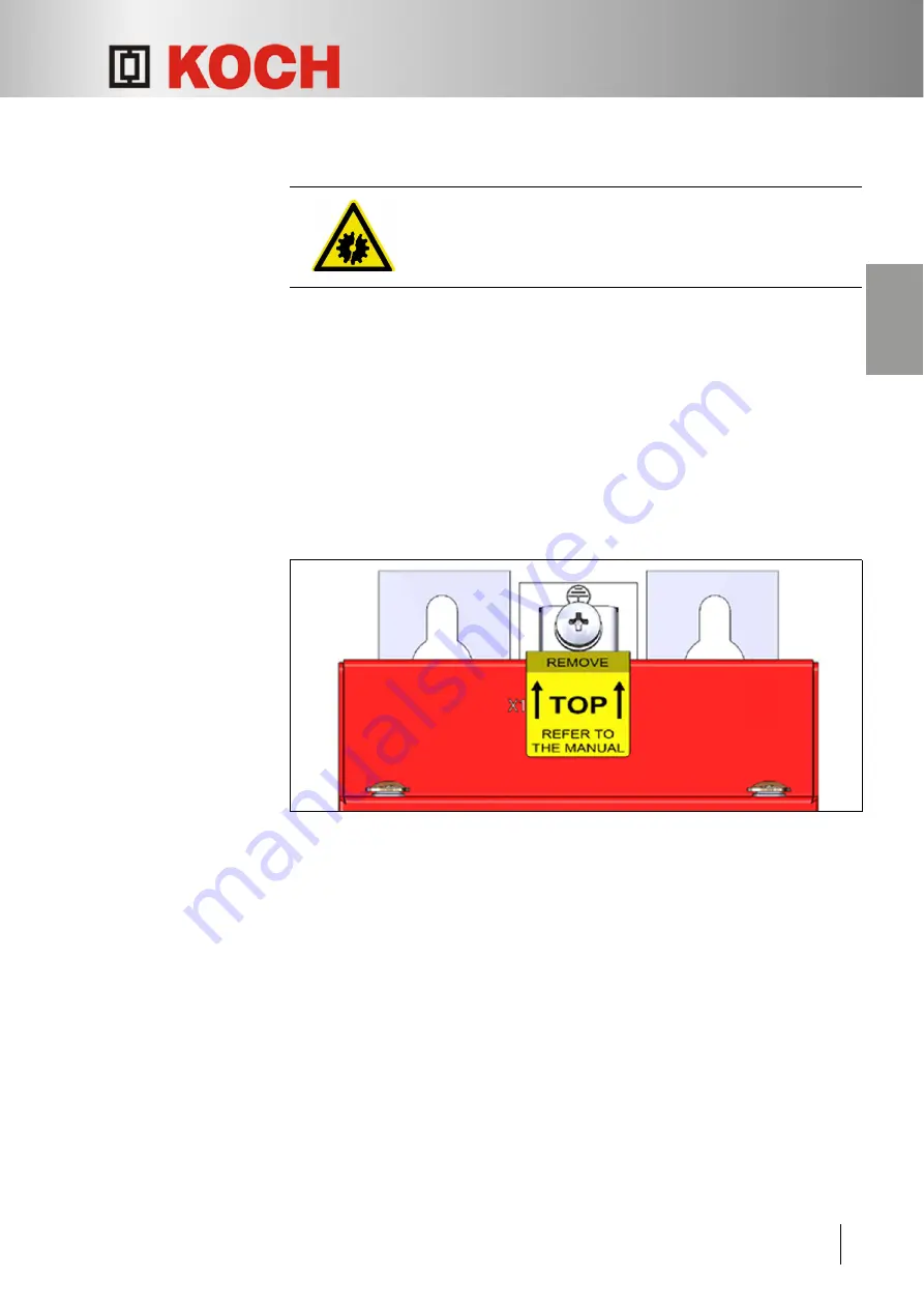
• The installation location is marked with a "TOP" sticker.

Fig. 22:  "TOP" sticker

Risk of damage!
Assembly upside down is prohibited!

Install the PxtEX extension unit vertically.

Содержание PxtFX

Страница 1: ...Energizing Productivity Aktives Energiemanagement Ger t PxtFX Active Energy Management Device PxtFX Betriebsanleitung Operating manual...

Страница 2: ...d Any duplication adaptation or translation without prior written permission is prohibited unless it is under copyright law Copyright Michael Koch GmbH Technische nderungen vorbehalten Durch Weiterent...

Страница 3: ...10 3 Grundlegende Sicherheitshinweise 3 1 Personal 11 3 2 Ger t 11 4 Transport Lagerung Montage 4 1 Lieferung pr fen 13 4 2 Aktives Energiemanagement Ger t PxtFX transportieren 13 4 3 Aktives Energie...

Страница 4: ...r 31 8 1 1 Varianten 31 8 1 2 Ansicht von vorne 32 8 1 3 Anschluss oben 33 8 1 4 Anschl sse unten 33 8 2 Typenschild 34 8 3 Kennzeichnungen auf dem Geh use 34 8 4 Umgebungsbedingungen 34 8 5 Elektrisc...

Страница 5: ...rechend den lokalen Bestimmungen entsorgt oder an den Hersteller zur ck gesendet werden 1 3 Umgang mit dieser Betriebsanleitung 1 3 1 Zielgruppe Diese Betriebsanleitung richtet sich an qualifiziertes...

Страница 6: ...en in Grafiken mit Nummern z B gekennzeichnet Im Text erfolgt der Bezug zu dieser Position durch diese Nummer hinter dem zugeh rigen Detail DGUV Deutsche Gesetzliche Unfallversicherung EMV Elektromagn...

Страница 7: ...einen handlungsbezogenen Warnhinweis Sachschaden Gefahren mit m glichen Sachsch den werden wie folgt gekennzeichnet Piktogramm Signalwort Gefahr und Folgen GEFAHR Kennzeichnet eine Gef hrdung mit eine...

Страница 8: ...ation Zus tzliche Informationen werden wie folgt gekennzeichnet Applikation In dieser Betriebsanleitung wird Applikation stellvertretend f r Antriebseinheit mit Frequenzumrichter oder Servoantrieb ver...

Страница 9: ...zu nehmen das Ger t darf nicht in Betrieb genommen werden Die Verbindungskabel Querschnitt nach nationaler Norm zwischen dem aktiven Energiemanagement Ger t PxtFX und dem Zwischenkreis der Applikatio...

Страница 10: ...nnungsrichtlinie und der Richtlinie 2014 30 EU EMV Richtlinie 2 3 Typenbezeichnung 2 4 bersichtsbilder 2 4 1 Varianten Fig 1 Varianten PxtFX Pr fsumme Parametersatz Speichertyp Hardwarevariante Hardwa...

Страница 11: ...4 2 Ansicht von vorne Fig 2 Frontansicht PxtFX 1 Befestigungsl cher 4 St ck 6 5 2 Erdungsklemme 3 Anschl sse oben X1 X2 X3 4 Taste RESET 5 Betriebsanzeigen L3 L4 6 Warnschild 7 Erdungsklemme 8 Anschl...

Страница 12: ...hl sse oben Fig 3 Anschl sse PxtFX oben 2 4 4 Anschl sse unten Fig 4 Anschl sse PxtFX unten 1 Anschlussklemmenblock X1 DC Kreis Zwischenkreis und Brems Chopper 2 Stecker X2 K Bus Kommunikationsschnitt...

Страница 13: ...ltung des DC Kreis Zwischenkreis ist der Speicher noch geladen bitte die Bedienungsanleitung lesen Bedeutung Nach dem Abschalten der Applikation ist der Speicher im oder am PxtFX weiterhin geladen Die...

Страница 14: ...6 kJ PxtFX mit 1 Energiemodul 3 2 kJ PxtFX mit 2 Energiemodulen Speichertyp 71 0 kJ PxtFX 2 0 kJ PxtFX mit 1 Energiemodul 4 0 kJ PxtFX mit 2 Energiemodulen Standby Verluste 10 W Speicherstrom 20 A Da...

Страница 15: ...otfall gilt Durchf hrung von Erste Hilfe Ma nahmen am Gesch digten Arzt oder Betriebssanit ter rufen Vorgesetzte informieren Anweisungen der Vorgesetzten oder des Hilfspersonals ist Folge zu leisten 3...

Страница 16: ...ausreichender Abstand zu benachbarten Bauteilen einzu halten Bei Arbeiten an den Komponenten ist eine ausreichende Abk hlzeit vorzusehen oder es sind hitzefeste Schutzhandschuhe zu tragen Warnsymbole...

Страница 17: ...zu entnehmen Lieferung pr fen Verpackung auf Besch digungen untersuchen Sch den an der Verpackung und oder am Ger t sind umgehend bei der Transport firma zu reklamieren Die Schadensmeldung muss inner...

Страница 18: ...f r den Einbau in einen Elektro schaltschrank vorgesehen Das aktive Energiemanagement Ger t PxtFX muss vor dem Eindringen von Fremd k rpern durch den Einbau im Schaltschrank gesch tzt werden Die Monta...

Страница 19: ...t vier Schrauben M6 montieren Bei PxtFX Ger t mit Energiemodul en Aufkleber TOP ist oben Alle vier Schrauben anziehen Festen Sitz kontrollieren Bei PxtFX Ger t mit Energiemodul en Aufkleber TOP entfer...

Страница 20: ...das Energiemanagement Ger t PxtFX vom DC Kreis Zwischenkreis zu trennen solange die Speicher geladen sind Beim Verbinden eines Speichers mit dem PxtFX m ssen alle Speicher auch die im PxtFX internen e...

Страница 21: ...allen anderen F llen ist sofort R cksprache mit der Michael Koch GmbH zu nehmen das Ger t darf nicht in Betrieb genommen werden Grunds tzliches Die Betriebsst tten m ssen trocken und staubfrei sein D...

Страница 22: ...ng verwendbare Querschnitte Wenn m glich sind die Querschnitte zum Anschluss des PxtFX passend zur Anschlussleitung des Frequenzumrichters zu w hlen Ist dies nicht m glich gibt es zwei M glichkeiten 1...

Страница 23: ...ussschema Fig 10 Anschluss DC Kreis Zwischenkreis Polung der Anschl sse DC Kreis Zwischenkreis feststellen DC Kreis Zwischenkreis spannungsfrei schalten Spannungsfreiheit im DC Kreis Zwischenkreis fes...

Страница 24: ...ischenkreis mit Spannung versorgen Zwei oder mehr aktive Energiemanagement Ger te PxtFX parallel anschlie en Es k nnen auch mehrere aktive Energiemanagement Ger te PxtFX ber die Klemmen Drive X1 Pin 2...

Страница 25: ...d am letzten PxtFX Ger t muss der K Bus mit Abschlusswiderst nden 120 Ohm zwischen Pin 2 und Pin 4 abgeschlossen werden Fig 12 Notwendige Abschlusswiderst nde Pin Signal Beschreibung K_V Externe Spann...

Страница 26: ...gungsspannung und GND Digitalsignale m ssen direkt verbunden sein Anschlie bare Leiter Leiterquerschnitt eindr htig AWG 24 16 Leiterquerschnitt eindr htig 0 205 mm 1 31 mm Leiterquerschnitt feindr hti...

Страница 27: ...g von 24 V in Form eines externen Netzteils anzulegen Dadurch wird es m glich das Ger t unabh ngig von der Versorgung DC Kreis Zwischenkreis z B zu parametrisieren Digitalausg nge Pin 3 5 Typische Anw...

Страница 28: ...unkt der Fertigung steht auf dem Typenschild Seite 9 Fig 5 Beim Formieren wird das Energiemanagement Ger t PxtFX an die Zwischenkreis spannung angeschlossen ist aber nicht betriebsbereit Fig 15 Formie...

Страница 29: ...Bet tigung der BOOT Taste l nger als 5 Sekunden wird ein auf der eingelegten Micro SD Karte befindliches Update in den Flash Speicher geschrieben Danach wird das PxtFX Ger t mit den neuen Software Par...

Страница 30: ...n Adressen bestimmen die Slaves Die Adresse ergibt sich aus der Seriennummer des Ger tes Bei der Initialisierung leuchten die LEDs nacheinander wie folgt Phase 1 Phase 2 Phase 3 Phase 4 Phase 5 L1 Aus...

Страница 31: ...ter geben Ein Einzelger t ist immer Master Masterbestimmung LED blinkt Als Master wird das Ger t mit der h chsten Adresse bestimmt Die Adresse ist die Seriennummer des Ger tes Danach wechselt der Stat...

Страница 32: ...Einschub des Ger tes einschieben Taste BOOT l nger als 5 s dr cken Betriebsanzeige L2 leuchtet gelb Der Updateprozess beginnt mit dem Loslassen der Taste und kann einige Minuten in Anspruch nehmen Bet...

Страница 33: ...h Je nach Anzahl der Energiemodule kann das einige Minuten dauern Seite 38 Kap 8 10 Erweiterungseinheit PxtEX entladen ausbauen Warten bis die Betriebsanzeigen L1 bis L4 nicht mehr leuchten Speicher m...

Страница 34: ...s Energiemanagement Ger t PxtFX kann nur vom Hersteller repariert werden 7 4 Aktives Energiemanagement Ger t PxtFX entsorgen Aktives Energiemanagement Ger t PxtFX entladen und trennen Seite 29 Aktives...

Страница 35: ...ohne Energiemodulen An die Erweiterungseinheit PxtEX k nnen wei tere Erweiterungseinheiten PxtEX angeschlossen werden Eine Erweiterungseinheit PxtEX kann dabei aus dem Basisger t und weiteren ein bis...

Страница 36: ...r t PxtFX V1 1DE EN 32 8 Erweiterungseinheit PxtEX Deutsch 8 1 2 Ansicht von vorne Fig 19 Frontansicht PxtEX 1 Befestigungsl cher 4 St ck 6 5 2 Erdungsklemme 3 Anschluss oben X1 4 Warnschild 5 Anschl...

Страница 37: ...33 8 Erweiterungseinheit PxtEX Deutsch 8 1 3 Anschluss oben Fig 20 Anschluss PxtEX oben 8 1 4 Anschl sse unten Fig 21 Anschl sse PxtEX unten 1 Stecker X1 Entladewiderstand 1 Stecker X2 immer Richtung...

Страница 38: ...tel 2 7 Seite 10 8 5 Elektrische Anschlusswerte 8 6 Abmessungen und Gewicht 8 7 Transport und Lagerung Siehe aktives Energiemanagement Ger t PxtFX Kapitel 4 Seite 13 Maximale Energieaufnahme speichert...

Страница 39: ...h den Einbau im Schaltschrank gesch tzt werden Die Montage erfolgt direkt auf einer Montagefl che im Schaltschrank Abst nde Bei der Montage sind folgende Abst nde zu anderen Baugruppen einzuhalten Obe...

Страница 40: ...Das Erweiterungseinheit PxtEX mit vier Schrauben M6 aufrecht h ngend montieren Aufkleber TOP ist oben Alle vier Schrauben anziehen Festen Sitz kontrollieren Aufkleber TOP entfernen 58 58 280 8 5 8 5 2...

Страница 41: ...PxtEX Deutsch 8 9 Erweiterungseinheit PxtEX erden Fig 24 Erdungsanschluss Geh useunterseite Erweiterungseinheit PxtEX am Erdungsanschluss Ring oder Gabelkabelschuh M5 erden Querschnitt nach nationale...

Страница 42: ...ngseinheit PxtEX spannungsfrei schalten Klemme X1 und Klemme X2 oder Klemme X3 mit dem Kabel VBST PXT verbinden Mit einem Multimeter an Klemme X2 Pin 1 und 3 oder an Klemme X3 Pin 1 und 3 die Spannung...

Страница 43: ...nd 3 oder an Klemme X3 Pin 1 und 3 die Spannung messen Kabel VBST PXT so lange gesteckt lassen bis keine Spannung mehr messbar ist Erweiterungseinheit PxtEX ist entladen Sachschaden Das Verbinden von...

Страница 44: ...gseinheit PxtEX Klemme X1 mit dem Kabel VBST PXT verbinden Energiemanagement Ger t PxtFX wird entladen Einige Minuten abwarten Kabel VBST PXT am Energiemanagement Ger t PxtFX abziehen und mit einem Mu...

Страница 45: ...weiterungseinheit PxtEX Deutsch 3 Erweiterungseinheit PxtEX an Energiemanagement Ger t PxtFX anschlie en Fig 28 PxtFX an PxtEX anschlie en Entladenes Energiemanagement Ger t PxtFX Klemme X5 und entlad...

Страница 46: ...erbundenen Ger te entladen werden 1 Weitere zweite Erweiterungseinheit PxtEX entladen Fig 29 Weitere Erweiterungseinheit PxtEX entladen Klemme X1 und Klemme X2 oder Klemme X3 mit dem Kabel VBST PXT ve...

Страница 47: ...ngseinheit PxtEX Klemme X3 und zus tzliche Erweiterungseinheit PxtEX Klemme X1 mit dem Kabel VBST PXT verbinden Einige Minuten abwarten Kabel VBST PXT an der ersten Erweiterungseinheit PxtEX abziehen...

Страница 48: ...weiterungseinheit PxtEX anschlie en Fig 31 Weiteres PxtEX anschlie en Schon verbundener und entladener PxtEX PxtFX Verbund Klemme X3 und zus tzliche entladene Erweiterungseinheit PxtEX Klemme X2 mit d...

Страница 49: ...Personnel 11 3 2 The device 11 4 Transport Storage Installation 4 1 Checking the delivery 13 4 2 Transporting the PxtFX active energy management device 13 4 3 Storing the PxtFX active energy manageme...

Страница 50: ...t 8 1 Overview diagrams 31 8 1 1 Variants 31 8 1 2 Front view 32 8 1 3 Top connection 33 8 1 4 Bottom connections 33 8 2 Type plate 34 8 3 Labels on the housing 34 8 4 Ambient conditions 34 8 5 Electr...

Страница 51: ...l system Equipment Faulty equipment must be disposed of in accordance with local regulations or returned to the manufacturer 1 3 Working with this Operating manual 1 3 1 Target group This Operating ma...

Страница 52: ...age Important details are marked with numbers e g q in diagrams This is referred to in the text by this number after the associated detail DGUV Deutsche Gesetzliche Unfallversicherung German Statutory...

Страница 53: ...ple of an action related warning Property damage Dangers with possible property damage are identified as follows Pictogram Signal word Danger and consequences DANGER Indicates a danger with a high deg...

Страница 54: ...Introduction English Information Additional information is identified as follows Application Application stands for drive unit with frequency converter or servo drive in this Operating manual Pictogra...

Страница 55: ...onnecting cables cross section to comply with your national standards between the PxtFX active energy management device and the DC link of the application must be shorter than 2 0 m must be laid as a...

Страница 56: ...irective and Directive 2014 30 EU EMC Directive 2 3 Type designation 2 4 Overview diagrams 2 4 1 Variant Fig 1 PxtFX variants Checksum Parameter set Storage type Hardware variant Hardware version Devi...

Страница 57: ...lish 2 4 2 Front view Fig 2 Front view of PxtFX 1 Mounting holes 4x dia 6 5 2 Earth terminal 3 Top connections X1 X2 X3 4 RESET button 5 Operating displays L3 L4 6 Warning sign 7 Earth terminal 8 Bott...

Страница 58: ...connections Fig 3 Top PxtFX connections 2 4 4 Bottom connections Fig 4 Bottom PxtFX connections 1 Connecting terminal block X1 DC circuit DC link and brake chopper 2 Connector X2 K Bus communication i...

Страница 59: ...switching off the DC circuit DC link if the stor age is still charged please read the operator s manual Meaning After the application is switched off the storage in or on the PxtFX is still loaded The...

Страница 60: ...1 energy module 3 2 kJ PxtFX with 2 energy modules Storage type 71 0 kJ PxtFX 2 0 kJ PxtFX with 1 energy module 4 0 kJ PxtFX with 2 energy modules Standby losses 10 W Storage current 20 A permanent 4...

Страница 61: ...The following must be done in case of an emergency Provide first aid to all injured persons Call a doctor or your in house paramedic Notify your manager Follow the instructions from your managers and...

Страница 62: ...components must be maintained during installation When working on the components allow sufficient cooling time or wear heat resistant protective gloves Warning symbols Warning symbols are attached to...

Страница 63: ...larger deliveries will be given on the delivery note Checking the delivery Check the packaging for damage Immediately notify the transport company about any damage to the packaging and or the device T...

Страница 64: ...ive energy management device is intended to be installed in an electrical cabinet The PxtFX active energy management device must be protected against penetration of foreign bodies in the cabinet The u...

Страница 65: ...ur screws M6 In the case of the PxtFX device with energy module s The TOP sticker is at the top Tighten all four screws Check that it is firmly seated In the case of the PxtFX device with energy modul...

Страница 66: ...nnect the PxtFX energy management device from the DC circuit DC link as long as the storage units are charged When connecting a storage unit to the PxtFX all storage units including those internal to...

Страница 67: ...non regenerative application In all other cases Michael Koch GmbH must be consulted immediately the device must not be put into operation Basic information The places of operation must be dry and dust...

Страница 68: ...le the cross sections for connecting the PxtFX should be selected to match the connecting cable of the frequency inverter If this is not possible there are two options 1 Select a short circuit proof c...

Страница 69: ...ction diagram Fig 10 DC circuit DC link connection Determine the polarity of the DC circuit DC link connections De energise the DC circuit DC link Ensure that there is no voltage in the DC circuit DC...

Страница 70: ...ment device Supply the DC circuit DC link with voltage Connect two or more PxtFX active energy management devices in parallel Several PxtFX active energy management devices can also be connected in pa...

Страница 71: ...n the first and last PxtFX device the K Bus must be terminated with terminating resistors 120 ohm between pin 2 and pin 4 Fig 12 Necessary terminating resistors Pin Signal Description K_V External pow...

Страница 72: ...irectly connected Connectable conductors Conductor cross section single core according to AWG 24 16 Conductor cross section single core 0 205 mm 1 31 mm Conductor cross section fine core according to...

Страница 73: ...2 in the form of an external power supply This makes it possible for example to parameterise the device independently of the supply DC circuit DC link Digital outputs Pin 3 5 Typical applications Rea...

Страница 74: ...nufacture is on the model plate Page 9 Fig 5 During conditioning the PxtFX energy management device is connected to the DC link but is not ready for use Fig 15 Conditioning time depending on the volta...

Страница 75: ...ton If the BOOT button is pressed for longer than 5 seconds an update on the inserted micro SD card is written to the flash memory Then the PxtFX device is started with the new software parameters Pag...

Страница 76: ...addresses determine the slaves The address results from the serial number of the device During initialization the LEDs light up one after the other as follows Phase 1 Phase 2 Phase 3 Phase 4 Phase 5 L...

Страница 77: ...gle device is always the master Master determination LED is flashing The device with the highest address is determined as the master The address is the serial number of the device After that the statu...

Страница 78: ...e Press the BOOT button for longer than 5 seconds Operating display L2 lights up yellow The update process starts when the button is released and may take a few minutes Operating display Description L...

Страница 79: ...f 24 V PxtFX is discharging Depending on the number of energy modules this can take several minutes Page 38 chap 8 10 Discharging removing the PxtEX extension unit Wait until the operating displays L1...

Страница 80: ...active energy management device can only be repaired by its manufacturer 7 4 Disposing of the PxtFX active energy management device Discharge and disconnect the PxtFX active energy management device...

Страница 81: ...th and without energy modules Additional PxtEX extension units can be connected to the PxtEX extension unit In the process a PxtEX expansion unit can consist of the base unit and one or two additional...

Страница 82: ...agement device V1 1DE EN 32 8 PxtEX extension unit English 8 1 2 Front view Fig 19 Front view of PxtEX 1 Mounting holes 4x dia 6 5 2 Earth terminal 3 Top connection X1 4 Warning sign 5 Bottom connecti...

Страница 83: ...n unit English 8 1 3 Top connection Fig 20 Top connection PxtEX 8 1 4 Bottom connections Fig 21 Bottom connections PxtEX 1 Connector X1 discharge resistor 1 Connector X2 always in the direction of the...

Страница 84: ...lectrical supply data 8 6 Dimensions and weight 8 7 Transport and storage See PxtFX active energy management device Chapter 4 page 13 Maximum energy consumption depending on storage type Storage type...

Страница 85: ...the installation into the cabinet The unit is installed directly on a mounting surface in the control cabinet Spacing During installation the following spacings to other modules must be maintained Ab...

Страница 86: ...tEX extension unit according to the drilling template vertically using four screws M6 The TOP sticker is at the top Tighten all four screws Check that it is firmly seated Remove the TOP sticker 58 58...

Страница 87: ...8 9 Earthing the PxtEX extension unit Fig 24 Earthing connection on the bottom of the housing Earth PxtEX extension unit to the earth connection q ring or forked cable lug M5 cross section according...

Страница 88: ...nnect the PxtEX extension unit from power supply Connect terminal X1 and terminal X2 or terminal X3 with the VBST PXT cable Measure the voltage at terminal X2 pins 1 and 3 or at terminal X3 pins 1 and...

Страница 89: ...e voltage at terminal X2 pins 1 and 3 or at terminal X3 pins 1 and 3 with a multimeter Leave the VBST PXT cable plugged in until no more voltage is measured The PxtEX extension unit is discharged Risk...

Страница 90: ...d the PxtEX extension unit terminal X1 with the VBST PXT cable The PxtFX energy management device is discharged Wait a few minutes Disconnect the VBST PXT cable from the PxtFX energy management device...

Страница 91: ...EX extension unit English 3 Connecting the PxtEX extension unit to the PxtFX energy management device Fig 28 Connecting the PxtFX to the PxtEX Connect the discharged PxtFX energy management device ter...

Страница 92: ...t be discharged 1 Discharging an additional second PxtEX extension unit Fig 29 Discharging an additional PxtEX extension unit Connect terminal X1 and terminal X2 or terminal X3 with the VBST PXT cable...

Страница 93: ...reviously connected PxtEX extension unit terminal X3 and the additional PxtEX extension unit terminal X1 with the VBST PXT cable Wait a few minutes Disconnect the VBST PXT cable from the PxtEX extensi...

Страница 94: ...econd PxtEX extension unit Fig 31 Connecting an additional PxtEX Connect the previously connected and discharged PxtEX PxtFX network terminal X3 and the additional discharged PxtEX extension unit term...

Страница 95: ...Operating manual PxtFX active energy management device V1 1DE EN 45 Notes English...

Страница 96: ......

Отзывы: