


LFM
Page 4
LFM K03/0422
4. Regulation Use
The LFM is a new flowmeter designed for use on clean low-viscosity liquids and
is particularly suitable for dosing and filling applications. Extremely low flow rates
can be measured down to 0.005 l/min. Care should be taken that liquid which
may attack the wetted parts of the flowmeter are not used.
Please ensure that all steps in this manual are observed as the flowmeters war-
ranty does not cover damage resulting from failure to comply with these
instructions.
We recommend a filter with 40 µm mesh size.
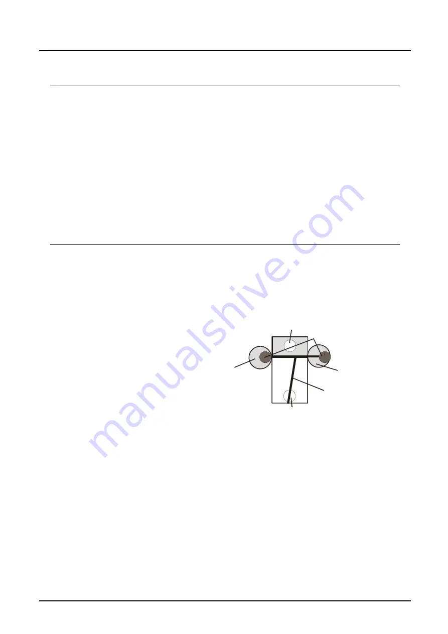
5. Operating Principle
The measuring mechanism is based on a dual-ring piston pendulum. The right-
hand measuring chamber is opened, and the left-hand chamber closed, by the
pendulum arm that is inclined to the right. The pressure of the forced liquid acts
on the upper surface of the piston pendulum. The right-hand ring piston is
pressed clockwise downwards, and the left-hand ring piston is pressed clockwise
upwards by the larger surface (opened measuring chamber) on the right. Thus
the right-hand measuring
chamber is closed, and
the left-hand chamber
opened. The surface on
the left is now greater –
causing motion in the
opposite direction. This
cycle is repeated with
continuous flow at a rate
proportional to the flow
rate 1–230 cycles/s. A volume of approximately 0.01 cm
3
is displaced per pass.
The built-in carrier frequency transducer senses the oscillating motion of the
piston pendulum and pendulum arm without contact through the case, and
outputs a digital signal with a frequency proportional to the volumetric flow. Due
to the negligible pendulum mass and minimum friction loss, the LFM detects
minimum volumetric flow rates. Leakage loss is minimized by the piston design,
which also provides good linearity and repeatability.
Inlet bore
Outlet bore
Meas. Chamber 1
Pendulum
Ring piston
Meas. Chamber 2