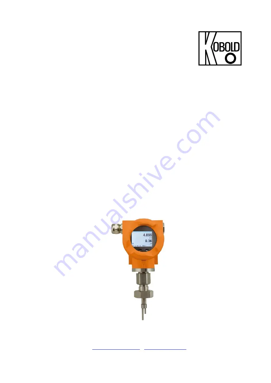
Kobold KEC-1 Скачать руководство пользователя страница 1


Operating Instructions 

for 

Thermal Energy Flowmeter 

for gases 


Model: KEC-1 


O

O

r

r

d

d

e

e

r

r


f

f

r

r

o

o

m

m

:

:


C

C


A

A


B

B

r

r

i

i

g

g

g

g

s

s


C

C

o

o

m

m

p

p

a

a

n

n

y

y


622 Mary Street; Suite 101; Warminster, PA 18974 

Phone: 267-673-8117 - Fax: 267-673-8118 

[email protected]

 - 

www.cabriggs.com


Содержание KEC-1

Страница 1: ...Energy Flowmeter for gases Model KEC 1 O Or rd de er r f fr ro om m C C A A B Br ri ig gg gs s C Co om mp pa an ny y 622 Mary Street Suite 101 Warminster PA 18974 Phone 267 673 8117 Fax 267 673 8118 S...

Страница 2: ...ration manual carefully before mounting and initiating the device and follow our advice A riskless operation and a correct functioning of the KEC 1 are only guaranteed in case of careful observation o...

Страница 3: ...dard Version 11 4 2 2 Measuring range Max Version 13 4 2 3 Measuring range High Speed Version 15 5 Dimensions 17 5 1 Dimension KEC 1 17 6 Installation 18 6 1 Pipe tube requirements 18 6 2 Inlet outlet...

Страница 4: ...29 8 3 1 4 Definition of the reference conditions 30 8 3 1 5 Setting of Zeropoint and Low flow cut off 32 8 3 2 Modbus Setup 33 8 3 2 1 Modbus Settings 2001 2005 34 8 3 2 2 Values Register 1001 1500...

Страница 5: ...danger As a consequence of incorrect handling serious personal injury or death Warning Possible hazard As a consequence of incorrect handling possible serious injury or death Caution Imminent hazard A...

Страница 6: ...s manual must be carried out only by qualified personnel qualifications described below Professionals Technical staff The technical staff is based on his education training his knowledge of measuremen...

Страница 7: ...ified personnel which were authorized by the plant operator The personnel must read the operating instructions and understand and follow their instructions If carrying out welding work on the pipeline...

Страница 8: ...larm max 48 Vdc 0 5 A optional Modbus TCP HART ProfibusDP Profi Net Accuracy 1 5 m v 0 3 f s Standard version m v of meas value f s of full scale Accuracy 1 0 m v 0 3 f s Precision version m v of meas...

Страница 9: ...A 485 4 1 2 Current output 4 1 2 1 Aktive Galvanically isolated 4 20 mA RL 500 Ohm 4 1 2 2 Passive Galvanically isolated 4 20 mA RL 500 Ohm Vin 12 36 Vdc 4 1 3 Pulse Galvanically isolated dry contact...

Страница 10: ...s to analogue output 4 20 mA of Standard 0 600 m h Max Version 0 1197 59 m h Highspeed Version 0 1450 06 m h In case of use in other inner pipe diameter the diameter using the display version the diam...

Страница 11: ...214 6 129 4 36 0 266 3 244 8 416 3 263 4 236 7 254 0 261 1 157 4 36 3 270 7 249 2 423 8 268 2 241 0 258 5 265 9 160 3 1 1 2 39 3 320 1 294 7 501 2 317 2 285 0 305 7 314 4 189 5 40 0 332 5 305 7 519 8...

Страница 12: ...9 3 5579 5110 6 8691 6 5500 5 4942 6 5302 5 5452 5 3287 1 182 5 7323 6715 6 11421 2 7227 9 6494 9 6967 8 7164 9 4319 4 190 0 7947 7278 9 12379 2 7834 2 7039 7 7552 3 7765 8 4681 7 8 200 0 8816 8074 9...

Страница 13: ...488 7 830 8 526 0 472 6 506 8 521 1 314 3 36 3 541 06 497 5 845 8 535 5 481 1 515 9 530 5 320 0 1 1 2 39 3 639 84 588 3 1000 2 633 3 568 9 610 1 627 4 378 4 40 0 663 68 610 2 1037 5 656 9 590 1 632 8...

Страница 14: ...347 2 10982 9 9867 2 10581 1 10881 0 6562 2 182 5 14581 94 13407 5 22795 1 14432 2 12966 1 13904 1 14298 2 8623 0 190 0 15805 08 14532 1 24707 2 15642 8 14053 7 15070 4 15497 5 9346 4 8 200 0 17533 48...

Страница 15: ...52 591 8 1006 1 636 6 572 3 613 6 631 2 380 7 36 3 655 12 602 5 1024 2 648 1 582 6 624 7 642 5 387 5 1 1 2 39 3 774 73 712 5 1211 2 766 4 689 0 738 8 759 9 458 3 40 0 803 59 739 0 1256 3 795 0 714 6...

Страница 16: ...6 21006 1 13292 3 11948 7 12812 4 13178 3 7947 8 182 5 17655 97 16237 2 27603 2 17466 8 15701 2 16836 2 17317 0 10443 8 190 0 19136 96 17599 2 29918 6 18931 9 17018 2 18248 5 18769 6 11319 9 8 200 0...

Страница 17: ...Dimensions KEC 1 K01 1216 Page 17 of 43 5 Dimensions 5 1 Dimension KEC 1 Sensor lenght L mm H mm C1 220 441 C2 300 521 C3 400 621 C4 500 721 C5 600 821 C7 160 381 156 max 132 max H m a x L...

Страница 18: ...e the recommended inlet and outlet runs Table Inlet Outlet runs Flow obstruction before the measurement section Min length Inlet run L1 Min length Outlet run L2 Slight curve ellbow 90 12 x D 5 x D Red...

Страница 19: ...valve If no valid measuring point with a ball valve is available there are following ways to set up a measuring point 6 3 1 welded nipple with ball valve Important Ensure that the system is in shut d...

Страница 20: ...ned according to the direction of the airflow A depth scale engraved on the probe tube a flow alignment arrow and an aligning device will be of help for you Once the sensor has been aligned the adapte...

Страница 21: ...e is prevented by internal stop pins After that the housing connecting nut is firmly retighten Housing connection nut 6 6 Tightening torques To secure and guarantee of the function and tightness follo...

Страница 22: ...43 7 Connection diagram 7 1 Cable glands clamping ranges For ensuring the tightness and strain relief connector cables with the following diameters must be used KEC 1 Standard clamping range 5 9mm KE...

Страница 23: ...X1 Power supply 1 VB GND 2 VB 12V 36 Vdc X2 Modbus 1 Modbus B 2 Modbus shield 3 Modbus A X3 Analogue output 1 Pulse Alarm 2 Pulse Alarm 3 Direction input 4 GND X4 Current output 1 1 I Aktiv 2 I Aktiv...

Страница 24: ...ng to be minimized Not used cable entries must be closed with end caps Use of cables with cross section of 0 25mm 7 3 2 Power supply 7 3 3 Modbus termination If the sensor placed at the end oft he Mod...

Страница 25: ...and confirm by pressing OK Inputs or changes can be made with all white deposit fields selcted filed will be highlighted with yellow background Words in green font refer mainly to the pictures in the...

Страница 26: ...8 2 Main menu Switching to pages 2 4 or back by pressing key 391 23 391 1 minutes 410 34 AV Time Period for average value calculation could be changed under Sensor Setup Advanced AV Time After switchi...

Страница 27: ...s password protected Selection of a menu item or to change a value is done with the key a final move to the chosen menu item or takeover of the value change needs the confirmation by pressing the key...

Страница 28: ...order to change e g the unit first select by pressing key the field Units and then key OK Select with the key the correct unit and then confirm selection by pressing 2x OK Entering changing the diame...

Страница 29: ...n by pressing 2x OK Entering changing the consumption counter via button select the respective position and activate the position with the OK button By pressing the position value is incremented by 1...

Страница 30: ...ference Do not enter the operation pressure or the operation temperature under reference conditions Setup Sensor Setup Advanced Setup Sensor Setup Advanced Ref Pref Setup Sensor Setup Advanced Ref Tem...

Страница 31: ...rtime Setup Sensor Setup Advanced AV Time Under item Filtertime an attenuation can be defined Input values of 0 10000 in ms are possible The time period for averaging can be entered here Input values...

Страница 32: ...tion and activate it with OK By pressing the position value is incremented by 1 Confirm the input with OK and activate next number position Leave menu with button Back With the low flow cut off activa...

Страница 33: ...the sensor placed at the end of the Modbus system a termination is required Therefore the enclosed 120R resistor is to be connected at Pin 1 and Pin 3 of connector X2 For changes e g the sensor ID fir...

Страница 34: ...AB Middle Endian 8 3 2 2 Values Register 1001 1500 Modbus Register Register Address No of Byte Data Type Description Default Read Write Unit Comment 1101 1100 4 Float Flow in m h R 1109 1108 4 Float F...

Страница 35: ...Nltr before comma x R 1293 1292 4 UInt32 Consumption cf before comma x R 1299 1298 4 UInt32 Consumption Ncf before comma x R 1305 1304 4 UInt32 Consumption kg before comma x R 1311 1310 4 UInt32 Consu...

Страница 36: ...owed Entries are discarded and error message displayed The galvanically isolated output can be defined as pulse or alarm output Selection of field Relay Mode with key and change modus by pressing key...

Страница 37: ...be deleted Password input have to be inserted twice Confirmation of input password by pressing OK Factory settings for password at the time of delivery 0000 4 times zero With Brightness it is possible...

Страница 38: ...Operation KEC 1 K01 1216 Page 38 of 43 8 3 5 Advanced Settings Advanced By pressing Factory Reset the sensor is set back to the factory settings...

Страница 39: ...Flow to the channel CH 1 To make changes first select the value item with button and confirm Moving between the different measurements values or to deactivate the 4 20mA with setting to unused by pres...

Страница 40: ...ttings 4 20mA Error Current The scaling of the 4 20mA channel can be done automatically Auto Range on or manual AutoRange off With button select the menu item AutoRange select with OK the desired scal...

Страница 41: ...Air Both addresses Primary address and ID could be automatic searched in the M Bus system 8 4 2 Default values transmitted Value 1 with Unit Consumption m Value 2 with Unit Flow m h Value 3 with Unit...

Страница 42: ...Supplymentary Documentation KEC 1 K01 1216 Page 42 of 43 9 Supplementary Documentation Supplementary Documentation for Ex Version in preparation...

Страница 43: ...conformity with the standards noted below EN 55011 2011 Industrial scientific and medical equipment Radio frequency disturbance characteristics Limits and methods of measurement EN 61326 1 2013 Elect...

Страница 44: ...KEC 2 K01 1216 Page 1 of 35 Operating Instructions for Thermal Energy Flowmeter for gases Model KEC 2...

Страница 45: ...ration manual carefully before mounting and initiating the device and follow our advice A riskless operation and a correct functioning of the KEC 2 are only guaranteed in case of careful observation o...

Страница 46: ...4 Alarm 9 4 2 Measuring range flow KEC 2 10 5 Dimensions 11 5 1 Dimension KEC 2 Thread version 11 5 2 Dimension KEC 2 Flanged version 12 6 Installation 13 6 1 Pipe tube requirements 13 6 2 Inlet outl...

Страница 47: ...the reference conditions 22 8 3 1 5 Setting of Zeropoint and Low flow cut off 24 8 3 2 Modbus Setup 25 8 3 2 1 Modbus Settings 2001 2005 26 8 3 2 2 Values Register 1001 1500 26 Remark 27 8 3 3 Pulse...

Страница 48: ...danger As a consequence of incorrect handling serious personal injury or death Warning Possible hazard As a consequence of incorrect handling possible serious injury or death Caution Imminent hazard A...

Страница 49: ...ns manual must be carried out only by qualified personnel qualifications described below Professionals Technical staff The technical staff is based on his education training his knowledge of measureme...

Страница 50: ...ified personnel which were authorized by the plant operator The personnel must read the operating instructions and understand and follow their instructions If carrying out welding work on the pipeline...

Страница 51: ...eight freely selectable Alarm max 48 Vdc 0 5 A optional Modbus TCP HART ProfibusDP Profi Net Accuracy 1 5 m v 0 3 f s Standard version m v of meas value f s of full scale Accuracy 1 0 m v 0 3 f s Prec...

Страница 52: ...4 1 2 Current output 4 1 2 1 Aktive Galvanically isolated 4 20 mA RL 500 Ohm 4 1 2 2 Passive Galvanically isolated 4 20 mA RL 500 Ohm Vin 12 36 Vdc 4 1 3 Pulse Galvanically isolated dry contact Passiv...

Страница 53: ...ethane 3 Natural gas CH4 R 1 2 16 1 DN 15 90 80 140 85 90 50 R 3 4 21 7 DN 20 170 155 275 165 175 105 R 1 27 3 DN 25 290 260 460 280 290 170 R1 36 DN 32 530 470 830 505 525 310 R 1 41 9 DN 40 730 650...

Страница 54: ...1 mm A mm 1 2 21 3 16 1 300 210 176 4 165 7 20 3 4 26 9 21 7 475 275 179 2 165 7 20 1 33 7 27 3 475 275 182 6 165 7 25 1 1 4 42 4 36 475 275 186 9 165 7 25 1 1 2 48 3 41 9 475 275 189 9 165 7 25 2 60...

Страница 55: ...1 300 210 213 2 165 7 95 65 4 x 14 DN 20 26 9 21 7 475 275 218 2 165 7 105 75 4 x 14 DN 25 33 7 27 3 475 275 223 2 165 7 115 85 4 x 14 DN 32 42 4 36 475 275 235 7 165 7 140 100 4 x 18 DN 40 48 3 41 9...

Страница 56: ...e the recommended inlet and outlet runs Table Inlet Outlet runs Flow obstruction before the measurement section Min length Inlet run L1 Min length Outlet run L2 Slight curve ellbow 90 12 x D 5 x D Red...

Страница 57: ...e rotated to the desired position a bigger rotaion angle is prevented by internal stop pins After that the housing connecting nut is firmly retighten 6 4 Tightening torques To secure and guarantee of...

Страница 58: ...onnection diagram 7 1 Cable glands clamping ranges For ensuring the tightness and strain relief connector cables with the following diameters must be used KEC 2 Standard clamping range 5 9 mm KEC 2 Ex...

Страница 59: ...wer supply 1 VB GND 2 VB 12 V 36 Vdc X2 Modbus 1 Modbus B 2 Modbus shield 3 Modbus A X3 Analogue output 1 Pulse Alarm 2 Pulse Alarm 3 Direction input 4 GND X4 Current output 1 1 I Aktiv 2 I Aktiv X5 C...

Страница 60: ...d with end caps Use of cables with cross section of 0 25 mm 7 3 2 Power supply 7 3 3 Modbus termination If the sensor placed at the end oft he Modbus system a termination is required Therfore the encl...

Страница 61: ...ll white deposit fields selcted filed will be highlighted with yellow background Words in green font refer mainly to the pictures in the section of the chapter but also on important menu paths or menu...

Страница 62: ...verage value calculation could be changed under Sensor Setup Advanced AV Time 8 3 Settings The settings menu could accessed by pressing the key OK But the access to the settings menu is password prote...

Страница 63: ...uspended as voted on included measuring section with corresponding pipe diameter For changes first select the menu item with key and then confirm it with OK Selection of a menu item or to change a val...

Страница 64: ...n by pressing 2x OK Entering changing the consumption counter via button select the respective position and activate the position with the OK button By pressing the position value is incremented by 1...

Страница 65: ...ference Do not enter the operation pressure or the operation temperature under reference conditions Setup Sensor Setup Advanced Setup Sensor Setup Advanced Ref Pref Setup Sensor Setup Advanced Ref Tem...

Страница 66: ...rtime Setup Sensor Setup Advanced AV Time Under item Filtertime an attenuation can be defined Input values of 0 10000 in ms are possible The time period for averaging can be entered here Input values...

Страница 67: ...position and activate it with OK By pressing the position value is incremented by 1 Confirm the input with OK and activate next number position Leave menu with button Back With the low flow cut off a...

Страница 68: ...the sensor placed at the end of the Modbus system a termination is required Therefore the enclosed 120R resistor is to be connected at Pin 1 and Pin 3 of connector X2 For changes e g the sensor ID fir...

Страница 69: ...AB Middle Endian 8 3 2 2 Values Register 1001 1500 Modbus Register Register Address No of Byte Data Type Description Default Read Write Unit Comment 1101 1100 4 Float Flow in m h R 1109 1108 4 Float F...

Страница 70: ...Nltr before comma x R 1293 1292 4 UInt32 Consumption cf before comma x R 1299 1298 4 UInt32 Consumption Ncf before comma x R 1305 1304 4 UInt32 Consumption kg before comma x R 1311 1310 4 UInt32 Consu...

Страница 71: ...owed Entries are discarded and error message displayed The galvanically isolated output can be defined as pulse or alarm output Selection of field Relay Mode with key and change modus by pressing key...

Страница 72: ...4 times With the last figure could be deleted Password input have to be inserted twice Confirmation of input password by pressing OK With Brightness it is possible to adjust the backlight display bri...

Страница 73: ...Operation KEC 2 K01 1216 Page 30 of 35 8 3 5 Advanced Settings Advanced By pressing Factory Reset the sensor is set back to the factory settings...

Страница 74: ...erature Velocity und Flow to the channel CH 1 To make changes first select the value item with button and confirm Moving between the different measurements values or to deactivate the 4 20mA with sett...

Страница 75: ...ttings 4 20mA Error Current The scaling of the 4 20mA channel can be done automatically Auto Range on or manual AutoRange off With button select the menu item AutoRange select with OK the desired scal...

Страница 76: ...ddresses Primary address and ID could be automatic searched in the M Bus system 8 4 2 Default values transmitted Value 1 with Unit Consumption m Value 2 with Unit Flow m h Value 3 with Unit Gas temper...

Страница 77: ...Supplymentary Documentation KEC 2 K01 1216 Page 34 of 35 9 Supplementary Documentation Supplementary Documentation for Ex Version in preparation...

Страница 78: ...mity with the standards noted below EN 55011 2011 Industrial scientific and medical equipment Radio frequency disturbance characteristics Limits and methods of measurement EN 61326 1 2013 Electrical e...

Страница 79: ...Installation and Operating Instructions for Service Software Model KEC Soft...

Страница 80: ...pdate Language 8 2 1 5 XML Settings 8 2 2 Sensor Settings 9 2 2 1 General 9 2 2 2 Gas 9 2 2 3 Units 10 Save the new unit using the Set button 10 2 2 4 Parameter 10 2 2 5 Zero Point Adjustment 11 2 3 A...

Страница 81: ...cturer 1 2 Connecting the device to the Service Software Adapter Please connect the Service Software Adapter with the power grid Now connect the Service Software Adapter with plug A of the flow meter...

Страница 82: ...e the PC Service Software Adapter but your own Modbus converter please deactivate the control window CA5xx Enter the specific values of the flow meter in the red marked area above ID 1 Baud 19200 Stop...

Страница 83: ...a look at 2 2 Sensor Settings General Consumption Velocity Current flow velocity Temperature Current gas temperature Gas Current kind of gas Sensor Settings Gas Ref Press Current set reference pressur...

Страница 84: ...s different information s about the flow meter 2 1 1 Device Info General The menu item Device Info shows an overview about different specific information s For example the serial number HW SW Version...

Страница 85: ...ply Voltage The current supply voltage of the connected flow meter Internal Temperature The current internal temperature of the connected flow meter Run Time Counter Shows the total time of operation...

Страница 86: ...tware version please contact your sensor manufacturer 2 1 4 Update Language You can update your sensor with different language files at Update Language For more information please ask your manufacture...

Страница 87: ...pressing the Set button Sensor Location Enter up to 15 letters Text to be entered into the field and transferred to sensor by pressing the Set button 2 2 2 Gas At Selected Gas you can choose between d...

Страница 88: ...using the Set button 2 2 4 Parameter At the point Parameter you can change reference temperature reference pressure and also enter your system pressure To get correct measurement results the correct p...

Страница 89: ...0 00 m3 h Your entered value will be use as cut off value if you choose Low Flow Cut Off All measuring values below this value won t be shown at the display of the KEC The values below your entered va...

Страница 90: ...on the settings for the reference time could be adapted 2 3 1 Average Time Span Clear Min Max The average time span can be entered at this tab Minimal 1 minute Maximum 1440 minutes With the buttons Cl...

Страница 91: ...alue will be the measuring limit of the value that was set at Value if you choose Autoscale Please insert your specific limits at Scale 4mA Scale 20mA if you want to scale manually You can also enter...

Страница 92: ...unit for your pulse output at Unit You can change the pulse value at Value and the polarity at Polarity pos 0 1 neg 1 0 2 5 2 Alarm settings Please select Alarm with the button Mode Select now your d...

Страница 93: ...s possible 2 6 1 Modbus Settings Factory Settings Modbus ID 1 Baud 19200 Stop 1 Par even Data 8 WordOrder ABCD Little Endian or CDAB Middle Endian Sensor and master device settings have to correspond...

Страница 94: ...ear would be set automatically 2 7 2 Parameter There are different parameters to influence modify the measurement It is not recommended to change parameters without contacting the sensor manufacturer...

Страница 95: ...gs With Get you are receiving the interface parameter from the sensor With Set you are transferring changing the parameters Primary Adress could be set individual but must be unique in the system Rang...

Страница 96: ...perature in C By activation of Units as String the transmission mode is switched to the Variable Data Structure This allows you to select the values and there units individually All values stored in t...

Страница 97: ...KEC Soft KEC K01 0217 page 19 Manufactured and sold by Kobold Messring GmbH Nordring 22 24 D 65719 Hofheim Tel 49 0 6192 2990 Fax 49 0 6192 23398 E Mail info de kobold com Internet www kobold com...

Отзывы: