

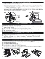


HOW TO ASSEMBLE THE HANDLE TUBE
Always unplug the machine before installing any accessory.
1.
Unplug machine, secure handle tube in vertical position and lay down the machine turning it over its wheels until the underneath side of the
machine is vertical and fully exposed.
2.
Before laying down machine, place a clean towel on the floor to keep the switch box from scratching.
3.
Install or replace pad. The pad should be replaced if it has become matted down to a thicknes of 3/8” or less.
4.
Remove existing pad then center new pad over grip face. Press pad against grip face until the hooks in the driver have set in the pad.
5.
Return the machine to the upright position.
6.
Do not operate this machine with out the pad in place.
7.
Always leave a pad on the machine to protect the grip face from damage.
1.
Plug the power cord into a proper grounded outlet.
2.
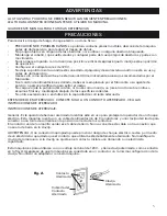
Adjust handle tube in a comfortable position by untighten the adjusting knob at the desired height.
3.
Press Switch lock and at the sime time, press the starting switch on the handle grip. The motor will start. WARNING: The chassis should be parallel
to the floor when you turn the machine on. It is recommended to familiarize with the machine by working on large spaces until you gain
experience with the machine.
4.
To turn the machine off simply release the starting switch while keeping hands on handle grip.
This unit works with 4 shock absorbers that reduce the vibration of the floor machine during operation.
If the unit vibrates or makes more noise than usual, then the replacement of the shock absorbers may be necessary.
To replace them follow these instructions:
1.
Always unplug the machine before replacing any part.
2.
Follow instructions 1 & 2 on how to assemble the pad.
3.
Remove the central part of the grip face pulling it off the pad driver.
4.
Remove the central screw on the bottom of the pad driver with a 3/4 wrench (Fig.1).
Note: To unscrew the central screw, you can use a screw driver to block the fan on top of the motor (Fig. 2) this will hold the screw from spinning.
5.
Remove the 4 screws that hold the pad driver with the chassis. (Fig. 3)
6.
Unscrew the 4 shock absorbers and replace with new ones (Fig. 4)
7.
Follow the same instructions in reverse to reassemble the unit.
HOW TO START YOUR FLOOR MACHINE
HOW TO REPLACE SHOCK ABSORBERS
HOW TO ASSEMBLE THE PAD
To assemble the handle tube (6) you need two 7/16 wrenches.
1.
Before assembling the handle tube (6) be sure the handle clamp (10) is positioned with the hole for the tube facing the motor (See fig. A).
2.
Slide the handle tube (6) through the handle clamp (10) hold the yoke (16) vertical and insert the tube over the yoke (See fig.A).
3.
Turn the handle tube (6) so the insert “Clean Freak Industrial” faces the motor, align the holes on the tube and the yoke, and place the two screws
(11) in the holes with the heads toward the wheels. (See fig. A).
4.
Place the safety nuts (12) on the screws with the flat part facing the screw, turn them manually until they get hard, then hold the head with
one 7/16 wrench and tighten the nut with the other wrench as far as it can go. (See fig. A).
5.
Tighten the adjusting knob (8) clockwise at a desired handle position until the handle clamp (10) does not slip when trying to tilt the machine.
6.
Connect the motor cable (9) making sure the insulating jacket is over the connectors.
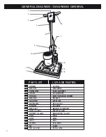
(11) Screw
(12)
Safety nut
(6) Handle tube
(10) Handle
clamp
(16) Yoke
Fig. A
Fig. 1
Fig. 2
Fig. 3
4
(8) Adjusting knob
untighten
tighten
Fig. B
Fig. 4
1
2
3
4


