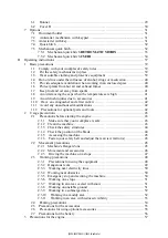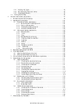
T
ABLE
O
F
C
ONTENTS
A
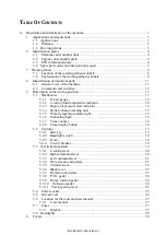
Description and illustration of the machine ........................................................ 1
1
Applications and regulations ................................................................... 3
1.1
Applications................................................................................ 3
1.2
Warranty .................................................................................. 3
1.3
Driving permits ............................................................................ 3
2
Identification plates .............................................................................. 4
2.1
Machine serial number plate ........................................................... 4
2.2
Engine serial number plate ............................................................. 4
2.3
EPA information plate ................................................................... 4
2.4
Spare parts order and intervention request ............................................ 5
3
Warning labels ..................................................................................... 6
3.1
Location of the warning adhesive labels .............................................. 6
3.2
Explanation of the warning adhesive labels .......................................... 8
4
Identification of important parts ..............................................................11
4.1
General view of the machine ..........................................................11
4.2
Commands and switches .............................................................. 12
5
Description of the driving position .......................................................... 13
5.1
Dashboard .............................................................................. 13
5.1.1
Diesel gauge .................................................................... 14
5.1.2
Cooling fluid temperature indicator ......................................... 14
5.1.3
Engine oil pressure alert indicator ........................................... 14
5.1.4
Battery charge warning alert ................................................. 15
5.1.5
Water temperature alarm light ............................................... 15
5.1.6
Preheating light ................................................................ 15
5.1.7
Time counter ................................................................... 16
5.1.8
Time display button ........................................................... 16
5.2
Switches ................................................................................. 17
5.2.1
Start key .......................................................................... 17
5.2.2
Headlight switch ................................................................ 18
5.2.3
Horn .............................................................................. 18
5.3
Joysticks and pedals .................................................................... 19
5.3.1
Locking lever .................................................................. 20
5.3.2
Right command lever .......................................................... 20
5.3.3
Left command lever ............................................................ 21
5.3.4
Travel levers and pedals........................................................ 21
5.3.5
Throttle
lever....................................................................
2
2
5.3.6
Blade lever ...................................................................... 23
5.3.7
Protection of pedals............................................................. 23
5.3.8
P.T.O. pedal ..................................................................... 24
5.3.9
Boom rotation pedal ........................................................... 24
5.3.10
2nd speed pedal .............................................................. 24
5.3.11
Track
spacing
lever
...........................................................
2
5
5.4
Power socket ............................................................................ 25
5.5
Driver's seat ............................................................................ 26
5.6
Location for the tools and user manual ............................................. 27
5.6.1
User manual .................................................................... 27
5.7
Fuses ..................................................................................... 27
5.7.1
Fusebox........................................................................... 27
5.8
Headlights ............................................................................... 28
6
Covers ........................................................................................... 29
5.2.
4
Circuit breaker
...........................................................
.....
...
18
[S2PU00027ZE02] [1204CsCshWbYs]
Содержание SK17SR
Страница 2: ...S2PU00027ZE02 1204CsCshWbYs...
Страница 4: ...S2PU00027ZE02 1204CsCshWbYs...
Страница 6: ...S2PU00027ZE02 1204CsCshWbYs...
Страница 8: ...S2PU00027ZE02 1204CsCshWbYs...
Страница 10: ...S2PU00027ZE02 1204CsCshWbYs...
Страница 18: ...2 S2PU00027ZE02 1204CsCshWbYs...
Страница 23: ...3 Warning labels 7 S2PU00027ZE02 1204CsCshWbYs...
Страница 52: ...36 S2PU00027ZE02 1204CsCshWbYs...
Страница 54: ...38 S2PU00027ZE02 1204CsCshWbYs...
Страница 114: ...98 S2PU00027ZE02 1204CsCshWbYs...
Страница 138: ...122 S2PU00027ZE02 1204CsCshWbYs...
Страница 140: ...124 S2PU00027ZE02 1204CsCshWbYs...
Страница 144: ...128 S2PU00027ZE02 1204CsCshWbYs...
Страница 146: ...130 S2PU00027ZE02 1204CsCshWbYs...
Страница 158: ...142 S2PU00027ZE02 1204CsCshWbYs...
Страница 159: ...B Notes 143 S2PU00027ZE02 1204CsCshWbYs...


