


58
NOTE
: If you examine the specifications of the LNB, you can find the operating range.
The operating frequency of the KU-down link is 10.95 ~ 12.75GHz = 1.8GHz of BW. But
the standard LNB covers 500 MHz of BW, while a wide-band LNB covers 750 MHz.
The output of 750 MHz LNB is 950~1700 MHz, but the extra 250 MHz may not be
useful if the satellite’s modem supports 950~1450 MHz.
No matter how good an LNB is, it will not be able to cover 1.8 GHz while meeting the
necessary RF performance. Thus, it is important to use an LNB that covers your operating
frequency.
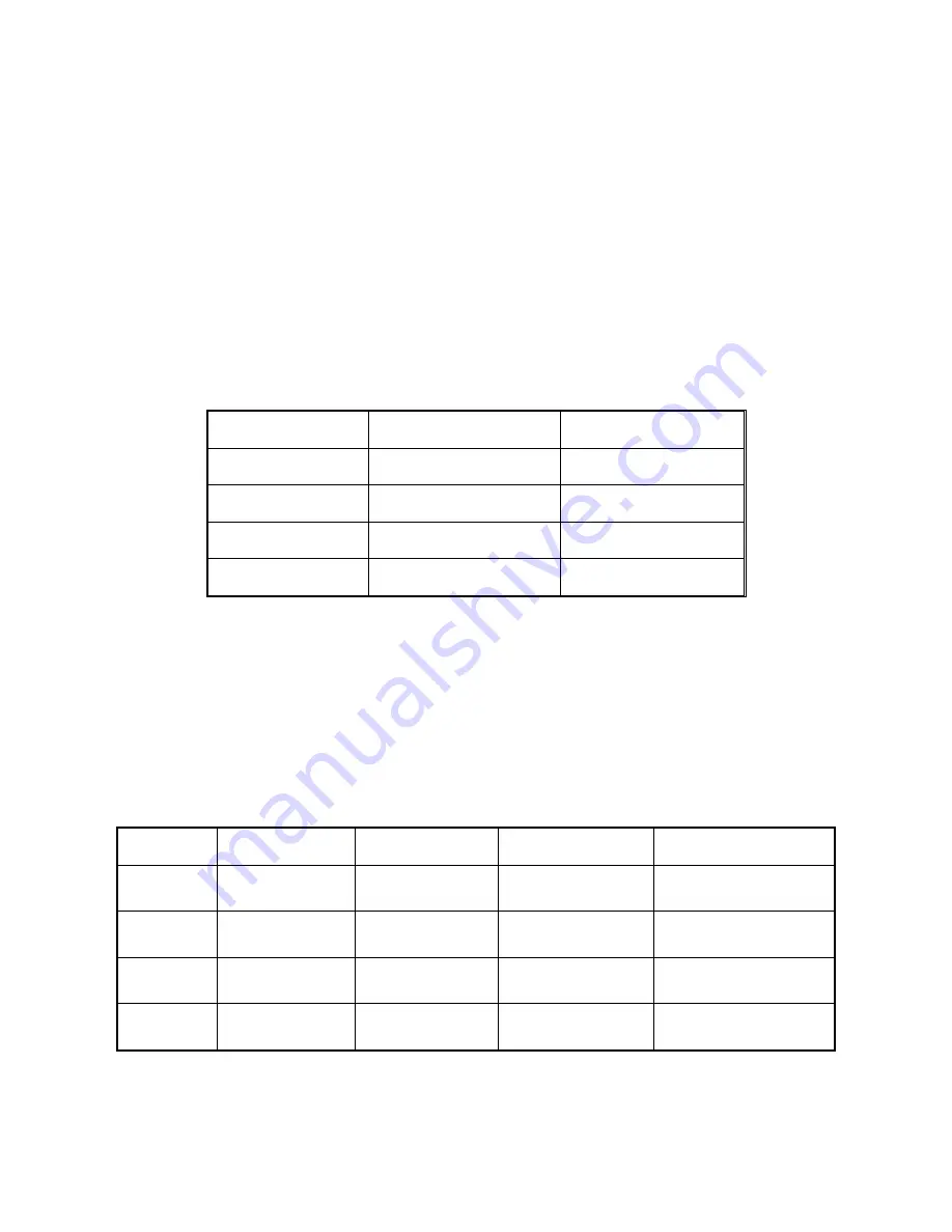
LNBs can be categorized by the fixed frequency of their local oscillator (LO).
LO ( GHz)
KU-Band In ( GHz)
L-band Out ( MHz)
10.00
10.95 ~ 11.70
950 ~ 1700
10.25
11.20 ~ 11.70
950 ~ 1450
10.75
11.70 ~ 12.20
950 ~ 1450
11.30
12.25 ~ 12.75
950 ~ 1450
Table 6-3 Operating Range by LNBs’ Local Frequencies
NOTE
: We provide a universal LNB that can cover the entire Ku-Band of
10.95~12.75GHz. This LNB has four local oscillators. The operator can select the desired
oscillator according to the LNB input voltage and 22KHz tone.
EXAMPLE
: If your desired RF frequency is 12.565GHz, you have to select the 11.3GHz
as LNB local frequency. For that, you must set the 11300MHz to ‘LNB Low Local
Frequency’, and then select [18V Low]. Please refer to the ‘DVB Tuner Configuration’ step.
LO( GHz)
LNB Voltage
22KHz Tone
KU-Band In (GHz)
L-band Out (MHz)
10.00
13VDC
OFF
10.95 ~ 11.70
950 ~ 1700
10.75
13VDC
ON
11.70 ~ 12.25
950 ~ 1500
11.30
18VDC
OFF
12.25 ~ 12.75
950 ~ 1450
9.75
18VDC
ON
10.70 ~ 11.70
950 ~ 1950
Table 6-4 Specifications of Universal LNB (Type R)
Содержание Ku-BAND RX
Страница 1: ...INSTALLATION AND OPERATION MANUAL FOR VSAT VS61 Ku BAND TX RX ANTENNAS...
Страница 15: ...7 Figure 3 1 Best Location Figure 3 2 Antenna Blockages...
Страница 46: ...38 Figure 4 1 Step 1 of Reference Searching Definition...
Страница 56: ...48 D i s h Figure 5 7 Determining the Heading Discrepancy Ship s BOW Figure 5 8 Direction of the Heading Offset...
Страница 65: ...57 Figure 6 3 Co pol Kits Optional...
Страница 76: ...68 when the key is pressed If you want to stop the skew pull out the key Figure 7 11 Skew in Jog Mode...
Страница 99: ...91 SEN VEL Angular Velocity of Elevation Cross Azimuth Axis Figure 7 37 Diagnostic for Sensor and Driver...
Страница 120: ...d Appendix C Layout of Radome and Antenna Mounting Holes Figure C 1 Plastic Radome...
Страница 121: ...e Figure C 2 FRP Radome Option...
Страница 122: ...f...
Страница 123: ...g Maritime Satellite Antenna...


