background image

Installation & Operation Manual

59

11  

Operating information 

(continued)

OPERATION

DISPLAY

1. Upon a call for heat, the control turns on the appropriate pumps

(system and boiler pumps for space heating call; DHW pump for
DHW call).

BLR: Standby
OUT:  123.8F(129)

2. The control connects 120 vac to the blower.  The blower does 

not run at this time.

• If the unit is equipped with a flow switch or low water cutoff, it 

must close before the control powers up the blower.

• If the unit is equipped with a manual reset high limit it must be 

closed before the control powers up the blower.

• If the unit is equipped with a solenoid valve and/or a vent 

valve, they will be energized along with the blower.

• If the unit is equipped with a gas pressure switch, it must close 

at this time.

• If there is an auxiliary device connected to the unit, the unit will 

then provide 24 vac to its enable relay.  If the auxiliary device 
has a proving switch, it must close before the sequence 
continues.

BLR: Standby
OUT:  123.8F(129)

3. The control then starts a 10 second prepurge cycle.  

BLR:  PREPURGE

OUT:  123.9F(129)

4. Once the prepurge cycle is complete, and the blocked drain 

and auto-reset high limit are closed, the control starts the 5 
second trial for ignition by sending spark voltage to the spark 
electrode and opening the gas valve.

BLR:  IGNITION
OUT:  123.9F(129)

5. If the control does not detect flame by the end of the trial for 

ignition, the control performs a 10 second postpurge, another 
prepurge and tries to light the burner again.  If the burner does 
not light after 4 trials, the control locks out for 1 hour and then 
tries another set of 4 trials.

BLR:  POSTPURGE,  PREPURGE
OUT:  123.9F(129)

6. If the control detects a flame before the trial for ignition ends, it 

begins to modulate the burner in order to maintain the set point.   
If the boiler lights due to a space heating call for heat, and the 
ramp delay function is active (default is active), the modulation 
will be held to a series of increasing limits after the burner has 
lit.

BLR:  SH  20%  RATE
OUT:  124.8F(129)

7. If the space heating call for heat is active, and the DHW

thermostat closes, the control will turn on the DHW pump, wait 2
seconds, and then turn off the boiler pump.  This will divert the hot
water away from the heating zone(s) and send it to the DHW tank
instead.  The control will then modulate to maintain the outlet
temperature to the DHW boiler set point.

BLR:  DHW  85%  RATE
OUT:  177.8(180)

Sequence of operation

Содержание 50 - 210

Страница 1: ... service technician Read all instructions including this manual and the Knight Wall Mount Service Manual before installing Perform steps in the order given Failure to comply could result in severe personal injury death or substantial property damage WARNING Save this manual for future reference WB I O Rev H ...

Страница 2: ... Air Piping 16 PVC CPVC Vent Piping Materials 16 Requirements for Installation in Canada 16 PVC CPVC Air Intake Vent Connections 17 Air Inlet Pipe Materials 17 Stainless Steel Vent 18 Max Allowable Vent Piping Lengths 19 Vent and Air Piping 19 Optional Room Air 20 4 SIDEWALL DIRECT VENTING Vent Air Termination Sidewall 21 24 Determine Location 21 22 Prepare Wall Penetrations 23 Termination and Fit...

Страница 3: ...esult in substantial property damage Do not use homemade cures or boiler patent medicines Serious damage to the boiler personnel and or property may result Continual fresh make up water will reduce boiler life Mineral buildup in the heat exchanger reduces heat transfer overheats the stainless steel heat exchanger and causes failure Addition of oxygen carried in by makeup water can cause internal c...

Страница 4: ... provides a wide range of firing rates 13 Water outlet system supply The water outlet is the water connection for water leaving the boiler and entering the system Boiler connection is 1 14 Water inlet system return The water inlet is the water connection for water entering the boiler from the system Boiler connection is 1 15 Gas connection pipe Threaded pipe connection of 1 2 This pipe should be c...

Страница 5: ...ration Manual Front View 8 20 7 3 14 13 29 6 31 16 7 27 Left Side inside unit 24 25 1 2 4 5 22 18 26 Right Side inside unit The Knight Wall Mount Boiler How it works continued FRONT OF UNIT Bottom View 5 Models 50 210 ...

Страница 6: ...t above 3 000 feet High altitude models are manufactured with a different control module for altitude operation but the operation given in this manual remains the same as the standard boilers A high altitude label as shown in FIG A is also affixed to the unit Maximum allowed working pressure is located on the rating plate NOTICE Knight Wall Mount Boiler I B R Rating Model Number Note Change N to L...

Страница 7: ...nsion tank Lack of freeze protection in boiler water causing system and boiler to freeze and leak WARNING This appliance is certified as an indoor appliance Do not install the appliance outdoors or locate where the appliance will be exposed to freezing temperatures or to temperatures that exceed 100 F Failure to install the appliance indoors could result in severe personal injury death or substant...

Страница 8: ...MUST BE used in a closet structure due to elevated temperatures Failure to follow this warning could result in fire personal injury or death Note Service clearances are recommendations only Note Service clearances are recommendations only WARNING For alcove installations CPVC or stainless steel material MUST BE used in an alcove structure due to elevated temperatures Failure to follow this warning...

Страница 9: ...Code ANSI Z223 1 and or CAN CGA B149 Installation Code Appliances located in residential garages and in adjacent spaces that open to the garage and are not part of the living space of a dwelling shall be installed so that all burners and burner ignition devices are located not less than 18 inches 46 cm above the floor The appliance shall be located or protected so that it is not subject to physica...

Страница 10: ...ust be used at the flue collar connection Size To ensure proper pipe size is in place see Table 3C Check to see that this size is used throughout the vent system Manufacturer For a stainless steel application you must use only the listed manufacturers and their type product listed in Table 3A for CAT IV positive pressure venting with flue producing condensate Supports Non combustible supports must...

Страница 11: ...re located and other spaces of the building Turn on clothes dryers and any appliance not connected to the common venting system Turn on any exhaust fans such as range hoods and bathroom exhausts so they will operate at maximum speed Do not operate a summer exhaust fan Close fireplace dampers d Place in operation the appliance being inspected Follow the lighting instructions Adjust thermostat so ap...

Страница 12: ... switch on the gas valve and turn the power switch to the OFF position FIG 2 2 4 Disconnect the Molex plug from the wiring connector located on the gas valve 5 Using a 5 16 nut driver loosen the band clamp securing the air intake coupler to the gas valve venturi Remove the air intake pipe and coupler from the gas valve venturi 6 Using a 4mm Allen wrench remove the two 2 screws securing the gas val...

Страница 13: ...ds 3 Hang the boiler on the bracket and secure the bottom of the boiler with two 2 field supplied toggle bolts WARNING Do not mount the boiler to a hollow wall Be sure to mount the boiler to the studs only Mounting the boiler See page 9 of this manual for boiler mounting location instructions NOTICE The Knight Wall Mount boiler is not intended for floor installation Mounting to a wood studded wall...

Страница 14: ...CPVC Two Pipe Sidewall Termination See page 21 for more details Figure 3 3 PVC CPVC Concentric Sidewall Termination See page 24 for more details Direct venting options Sidewall Vent Figure 3 2 Stainless Steel Two Pipe Sidewall Termination See page 22 for more details ...

Страница 15: ...tion See page 27 for more details Figure 3 7 PVC CPVC Vertical Vent Sidewall Air Figure 3 8 Stainless Steel Vertical Vent Sidewall Air Direct venting options Vertical Vent Direct venting options Vertical Vent Sidewall Air Stainless steel vent air design and terminations will vary slightly by manufacturer NOTICE Figure 3 6 PVC CPVC Concentric Vertical Termination See page 29 for more details ...

Страница 16: ...see Section 4 Sidewall Termination Optional Concentric Vent and the 2 and 3 Concentric Vent Kits available from IPEX are approved for use on the Knight wall mount boiler Both kits are listed to the ULC S636 standard for use in Canada For models 50 105 when transitioning from 2 to 3 inch vent diameter a 2 pipe section and 2 to 3 increaser are required to be CPVC when PVC CPVC vent is used For insta...

Страница 17: ... 305 Table 305 4 or as local codes dictate VENT AIR Figure 3 9 Near Boiler PVC CPVC Venting Air inlet pipe materials The air inlet pipe s must be sealed Choose acceptable combustion air inlet pipe materials from the following list PVC CPVC or ABS Dryer Vent or Sealed Flexible Duct not recommended for rooftop air inlet Galvanized steel vent pipe with joints and seams sealed as specified in this sec...

Страница 18: ...Table 3A Use only the materials vent systems and terminations listed in Table 3B DO NOT mix vent systems of different types or manufacturers unless listed in this manual Failure to comply could result in severe personal injury death or substantial property damage WARNING Installations must comply with applicable national state and local codes Stainless steel vent systems must be listed as a UL 173...

Страница 19: ...ational Building Code Section 305 Table 305 4 or as local codes dictate Maximum allowable combustion air and vent piping lengths are as follows Model 2 Max Vent Air 3 Max Vent Air 50 40 feet 100 feet 80 40 feet 100 feet 105 40 feet 100 feet 150 N A 100 feet 210 N A 100 feet Increasing or decreasing the size of the combustion air or vent piping beyond the sizes listed in Table 3C is not authorized ...

Страница 20: ...he equipment room MUST be provided with properly sized openings to assure adequate combustion air Please refer to instructions provided with the room air kit There will be a noticeable increase in the noise level during normal operation from the inlet air opening Using the room air kit makes the unit vulnerable to combustion air contamination from within the building Please review Section 1 Preven...

Страница 21: ...e plume could obstruct window views c Prevailing winds could cause freezing of condensate and water ice buildup where flue products impinge on building surfaces or plants d Avoid possibility of accidental contact of flue products with people or pets e Do not locate the terminations where wind eddies could affect performance or cause recirculation such as inside building corners near adjacent build...

Страница 22: ...to be damaged by foreign objects such as stones or balls or subject to buildup of leaves or sediment Vent air termination sidewall ALTERNATE VENTING ARRANGEMENT IF SPACE PERMITS BIRD SCREEN 12 MIN 12 MIN 15 MAX COUPLING TO BOILER INTAKE AIR CONNECTION FROM BOILER VENT PIPE CONNECTION BIRD SCREEN Figure 4 1C Alternate Venting Arrangement if Space Allows w Field Supplied Fittings VENT AIR TERMINATIO...

Страница 23: ...onal injury death or substantial property damage Multiple vent air terminations 1 When terminating multiple Knight wall mount boilers terminate each vent air connection as described in this manual FIG 4 5A 2 Place wall penetrations to obtain minimum clearance of 12 inches between edge of air inlet and adjacent vent outlet as shown in FIG 4 5A for U S installations For Canadian installations provid...

Страница 24: ...plants or air conditioning equipment or be objectionable b The flue products will form a noticeable plume as they condense in cold air Avoid areas where the plume could obstruct window views c Prevailing winds could cause freezing of condensate and water ice buildup where flue products impinge on building surfaces or plants d Avoid possibility of accidental contact of flue products with people or ...

Страница 25: ...lure to follow this warning could result in product damage or improper operation personal injury or death Figure 4 9 Rain Cap to Vent Pipe Alternate Assembly 6 Install the Y concentric fitting and pipe assembly through the structure s hole Do not allow insulation or other materials to accumulate inside the pipe assembly when installing through the hole 7 Install the rain cap and small diameter pip...

Страница 26: ...ent terminations be made as shown to avoid recirculation of flue gases Dimension A in FIG 4 11 represents the distance between pipes or rain shields as touching or a 2 inch maximum separation Figure 4 11 Concentric Vent and Combustion Air Termination Dimension A as Touching or 2 inches Maximum Separation Figure 4 10 Concentric Vent Sidewall Attachment DO NOT use field supplied couplings to extend ...

Страница 27: ...strated in FIG 5 1B maintain at least 36 914 mm above the air inlet The air inlet pipe and vent pipe can be located in any desired position on the roof but must always be no further than 2 feet 6 m apart and with the vent termination at least 1 foot above the air intake ALTERNATE INTAKE LOCATIONS INTAKE PIPES MAY BE LOCATED ANYWHERE WITHIN 24 OF VENT PIPE BIRD SCREEN TYPICAL COUPLING FIELD SUPPLIE...

Страница 28: ...as shown in FIG 5 1A The top of the coupling must be at least 1 foot above the air intake When the vent termination uses a rain cap as illustrated in FIG 5 1B maintain at least 36 914 mm above the air inlet The air inlet pipe and vent pipe can be located in any desired position on the roof but must always be no further than 2 feet apart and with the vent termination at least 1 foot above the air i...

Страница 29: ...secure the two 2 components together when field disassembly is desired for cleaning see FIG 4 9 page 25 When using the alternate screw assembly method drill a clearance hole in the rain cap and a pilot hole in the vent pipe for the screw size being used Failure to drill adequate holes may cause cracking of PVC components allowing combustion products to be recirculated Failure to follow this warnin...

Страница 30: ...ear each other each appliance must be individually vented see FIG 5 7 NEVER common vent or breach vent this appliance When two 2 or more direct vent appliances are vented near each other two 2 vent terminations may be installed as shown in FIG 5 7 The next two 2 vent terminations must be at least 36 inches away from the first two 2 terminations It is important that vent terminations be made as sho...

Страница 31: ...tallation of the Knight wall mount boiler reference FIG s 6 1A and 6 1B 1 Connect the system return marked Inlet make sure to install with pipe sealant compound 2 Connect the system supply marked Outlet make sure to install with pipe sealant compound 3 Install purge and balance valve or shutoff valve and drain on system return to purge air out of each zone 4 Install a backflow preventer on the col...

Страница 32: ...ED DOMESTIC HOT WATER PUMP CONDENSATE DRAIN SYSTEM PUMP BOILER PUMP FROM SYSTEM TO SYSTEM TO FROM INDIRECT DOMESTIC HOT WATER TANK TO FLOOR DRAIN Figure 6 1A Near Boiler Piping w Y Strainer VENT AIR TO FLOOR DRAIN AIR VENT VALVE AIR SEPARATOR SYSTEM SENSOR DRAIN TYPICAL SYSTEM PUMP LOW LOSS HEADER TYPICAL CONDENSATE DRAIN INDIRECT DOMESTIC HOT WATER TANK Y STRAINER RECOMMENDED DRAIN VALVE BOILER P...

Страница 33: ... 0 1 UPS15 58FC 0014 NRF 36 E7 105 7 7 17 5 1 UPS26 99F 0014 NRF 36 E7 150 11 0 12 8 1 UPS26 99F 0014 NRF 36 E7 210 15 5 19 0 1 UPS26 99F 0013 NRF 36 E7 35 F Temperature Rise Applications Model GPM FT HD Minimum Pipe Size Pump Grundfos TACO B G Armstrong 50 2 9 4 1 1 UPS15 58FC 007 NRF 22 Astro 30 80 4 2 7 3 1 UPS15 58FC 007 NRF 22 Astro 30 105 5 5 9 8 1 UPS15 58FC 007 NRF 22 Astro 30 150 7 9 10 1...

Страница 34: ... is shipped loose It is the responsibility of the contractor to install the temperature and pressure gauge on the boiler water outlet 10 Pressure relief valve Factory supplied The pressure relief valve is sized to ASME specifications 11 Boiler purge valve Field supplied The boiler purge valve is used to remove entrapped air from the heat exchanger during start up 12 System temperature sensor Lochi...

Страница 35: ... DRAIN POINT TYPICAL MAKE UP WATER HOT WATER OUT ZONE CIRCULATORS TYPICAL FLOW CHECK VALVE TYPICAL BOILER CIRCULATOR SYSTEM SUPPLY SENSOR PRESSURE RELIEF VALVE Y STRAINER RECOMMENDED MAY SUBSTITUTE LOW LOSS HEADER NOT TO EXCEED 4 PIPE DIA OR MAX OF 12 APART Figure 6 3 Single Boiler Zoned with Circulators 6 Hydronic piping continued Please note that these illustrations are meant to show system pipi...

Страница 36: ...YPICAL PRESSURE RELIEF VALVE HOT WATER OUT COLD WATER IN BOILER 1 LEADER SYSTEM SUPPLY SENSOR TEMPERATURE PRESSURE GAUGE DRAIN Y STRAINER RECOMMENDED TYPICAL MAY SUBSTITUTE LOW LOSS HEADER Figure 6 4 Multiple Boilers Zoned with Circulators Model Number of Units 2 3 4 5 6 7 8 Required Pipe Sizes 50 1 1 1 4 1 1 2 2 2 2 2 80 1 1 4 1 1 2 2 2 2 1 2 2 1 2 2 1 2 105 1 1 2 2 2 2 1 2 2 1 2 2 1 2 3 150 2 2 ...

Страница 37: ...OR BACKFLOW PREVENTER PRESSURE REDUCING VALVE PRESSURE GAUGE EXPANSION TANK ZONE 1 ZONE 2 ZONE 3 ZONE 4 ZONE VALVES TYPICAL FLOW CHECK VALVE NOT TO EXCEED 4 PIPE DIA OR MAX OF 12 APART DIFFERENTIAL PRESSURE BYPASS VALVE IF USED SYSTEM CIRCULATOR SYSTEM SUPPLY SENSOR DRAIN Y STRAINER RECOMMENDED MAY SUBSTITUTE LOW LOSS HEADER Figure 6 5 Single Boiler Zoned with Valves Please note that these illustr...

Страница 38: ...EADER DIFFERENTIAL PRESSURE BYPASS VALVE IF USED SYSTEM SUPPLY SENSOR SYSTEM CIRCULATOR DRAIN Y STRAINER RECOMMENDED TYPICAL NOT TO EXCEED 4 PIPE DIA OR MAX OF 12 APART MAY SUBSTITUTE LOW LOSS HEADER ZONE 3 Figure 6 6 Multiple Boilers Zoned with Valves Model Number of Units 2 3 4 5 6 7 8 Required Pipe Sizes 50 1 1 1 4 1 1 2 2 2 2 2 80 1 1 4 1 1 2 2 2 2 1 2 2 1 2 2 1 2 105 1 1 2 2 2 2 1 2 2 1 2 2 1...

Страница 39: ...E DRAIN POINT TYPICAL MAKE UP WATER FROM SYSTEM NOT TO EXCEED 4 PIPE DIA OR MAX OF 12 APART BOILER CIRCULATOR SYSTEM CIRCULATOR TO SYSTEM SYSTEM SUPPLY SENSOR DRAIN MAY SUBSTITUTE LOW LOSS HEADER Y STRAINER RECOMMENDED HOT WATER OUT Figure 6 7 Single Boiler Non Zoned Primary Secondary Piping 6 Hydronic piping continued Please note that these illustrations are meant to show system piping concept on...

Страница 40: ...urge all air from the gas supply piping 4 Before placing the boiler in operation check the boiler and its gas connection for leaks a Close manual main shutoff valve during any pressure testing at less than 13 inches w c b Disconnect the boiler and gas valve from the gas supply piping during any pressure testing greater than 13 inches w c The gas valve and blower will not support the weight of the ...

Страница 41: ...atural gas supply pressure requirements 1 Pressure required at the gas valve inlet pressure port Maximum 14 inches w c with no flow lockup or with boiler on Minimum 4 inches w c with gas flowing verify during boiler startup 2 Install 100 lockup gas pressure regulator in supply line if inlet pressure can exceed 14 inches w c at any time Adjust lockup regulator for 14 inches w c maximum Propane Gas ...

Страница 42: ... appliance WARNING 3 Loosen the set screw one 1 full turn from inside the pressure tap on top of the gas valve Place the tubing of the manometer over the tap once the set screw is loosened as shown in FIG 7 3 4 Slowly turn on the gas supply at the field installed manual gas valve 5 Turn the power switch to the ON position 6 Adjust the temperature set point on the control panel of the SMART SYSTEM ...

Страница 43: ...le in operating dynamic mode If an in line regulator is used it must be a minimum of 10 feet from the Knight wall mount boiler It is very important that the gas line is properly purged by the gas supplier or utility company Failure to properly purge the lines or improper line sizing will result in ignition failure The problem is especially noticeable in NEW LP installations and also in empty tank ...

Страница 44: ...adian Electrical Code Part 1 and any local codes Line voltage connections 1 Remove bezel as shown in FIG 8 1 2 Connect 120 vac power wiring to the line voltage terminal strip in the junction box as shown in FIG 8 2 2 Provide and install a fused disconnect or service switch 15 amp recommended as required by the code see FIG 8 2 3 Wire the boiler pump as shown in FIG 8 2 4 When connecting a domestic...

Страница 45: ...ce needs to operate when the boiler fires it can be controlled by this output Connect these terminals to a 24 vac relay coil which is wired to operate the auxiliary device FIG 8 4 Auxiliary device proving switch 1 When the operation of an auxiliary device needs to be verified before the boiler fires remove the jumper wire from these terminals and connect them to the normally open contacts on its p...

Страница 46: ...culate the water temperature set point based on the programmed reset curve parameters If the outdoor air sensor is not connected the Leader control will maintain the fixed water temperature set point that is programmed into the control If a Thermostat Zone Control enable output or Building Management System enable output are available it should be wired to the Low Voltage Connection Board on the L...

Страница 47: ...SWITCH TANK THERMOSTAT WALL THERMOSTAT ZONE CONTROL SYSTEM SUPPLY SENSOR OUTDOOR SENSOR BUILDING MANAGMENT SYSTEM AUX DEVICE PROVING SWITCH COM NO A B A B SHIELD SHIELD FROM PREVIOUS BOILER TO NEXT BOILER TANK SENSOR LOW WATER CUTOFF Figure 8 4 Low Voltage Field Wiring Connections ...

Страница 48: ...aterials approved by the authority having jurisdiction In the absence of other authority PVC and CPVC pipe must comply with ASTM D1785 or D2845 Cement and primer must comply with ASME D2564 or F493 For Canada use CSA or ULC certified PVC or CPVC pipe fittings and cement 7 A condensate removal pump is required if boiler is below drain When installing a condensate pump select one approved for use wi...

Страница 49: ...cation a The minimum cold water fill pressure for a residential system is 12 psi b Pressure will rise when boiler is turned on and system water temperature increases Eliminate all system leaks Continual fresh makeup water will reduce boiler life Minerals can build up in the heat exchanger reducing heat transfer overheating the heat exchanger and causing heat exchanger failure Purge air from water ...

Страница 50: ...e external circuit one at a time and check the voltmeter reading across the incoming wires 3 There should NEVER be a voltage reading 4 If a voltage does occur under any condition check and correct the external wiring This is a common problem when using 3 wire zone valves 5 Once the external thermostat circuit wiring is checked and corrected if necessary reconnect the external thermostat circuit wi...

Страница 51: ...ith circulation and cause heat distribution problems and noise Check vent piping and air piping 1 Check for gastight seal at every connection seam of air piping and vent piping Venting system must be sealed gastight to prevent flue gas spillage and carbon monoxide emissions which will result in severe personal injury or death Check gas piping 1 Check around the boiler for gas odor following the pr...

Страница 52: ...Installation Operation Manual 52 10 Start up Figure 10 2 Operating Instructions ...

Страница 53: ...e Verify space heat circulator mode The Space Heating Mode controls both the system primary pump if connected and the boiler secondary pump When the SMART SYSTEM control receives a space heating call for heat it turns on the system pump If the boiler is not heating an indirect DHW Domestic Hot Water tank it also turns on the boiler pump After the space heating call for heat ends the system pump co...

Страница 54: ...select which digit flashes 4 Press the ENTER key 5 The display changes to read USER CODE for a few seconds then displays a menu 6 Press the ENTER key 7 Press the UP key twice to display A3 DATE AND TIME 8 Press the ENTER key once 9 The date and time are displayed as YY MM DD W hh mm where mm minutes hh hour 24 hour time e g 2 00 PM 14 00 W day of the week 1 Sunday 2 Monday 3 Tuesday etc DD date MM...

Страница 55: ...r for maximum response and recovery The DHW pump continues for 30 seconds after the heating cycle to deliver the most possible heat DHW space heating SH cycling If a DHW call for heat is received while a space heating call is in progress the control will start the DHW pump and shut the boiler pump off The system pump will remain on If the space heating call is still active while the DHW call is in...

Страница 56: ...wns when the boiler is firing at minimum rates the control will increase the firing rate when the flame signal drops too low Protection features Outlet temperature flue temperature and temperature rise limiting The outlet temperature is monitored by the boiler outlet temperature sensor When the outlet temperature exceeds 185 F the unit will reduce the fan speed If the outlet water temperature exce...

Страница 57: ... be programmed into the control See page 53 of this manual to program the set point Monitor external limits Connections are provided on the connection board for external limits such as flow switch low water cutoff gas pressure switches and an auxiliary device proving switch The SMART SYSTEM will shut off the burner and inhibit relighting whenever any of these external limits open Run time and alar...

Страница 58: ...peration any boiler s in the Cascade can be selected to provide heat for a DHW call Select a boiler to be designated as the DHW boiler Connect the DHW thermostat to the terminals on the Low Voltage Connection Board marked for the DHW Thermostat When the boiler receives a DHW call the Leader control will take that boiler out of the Cascade sequence If another boiler is available the Leader will sta...

Страница 59: ...blocked drain and auto reset high limit are closed the control starts the 5 second trial for ignition by sending spark voltage to the spark electrode and opening the gas valve BLR IGNITION OUT 123 9F 129 5 If the control does not detect flame by the end of the trial for ignition the control performs a 10 second postpurge another prepurge and tries to light the burner again If the burner does not l...

Страница 60: ...perature by using the UP and DOWN buttons FIG 11 1 on page 61 at any time during normal operation By entering the USER code 0704 the user can also change temperature units time and date and night setback settings In User Mode the following parameters can be viewed but not changed Boiler outlet water target temperature in DHW Mode Boiler model number Software version Total operating hours Total cyc...

Страница 61: ...ration Manual 61 Knight wall mount boiler control module Figure 11 1 Control Panel Use the control panel FIG 11 1 to set temperatures operating conditions and monitor boiler operation 11 Operating information continued ...

Страница 62: ...r an additional 10 seconds to clear the combustion chamber and vent system of residual flue products Service The unit has been placed in a temporary mode that will allow the unit to fire at 100 of rate for the purpose of combustion analysis OUT F When the outlet sensor has been selected as the control sensor default the control will display the outlet temperature as well as the set point in parent...

Страница 63: ... wires or the sensor itself has become shorted Press the Next arrow key on the SMART SYSTEM display to access Screen 4 4 FLUE F The control will display the flue temperature Open The control does not detect the flue sensor Shorted The flue sensor wires or the sensor itself has become shorted AUX F The control will display the temperature Open The control does not detect the auxiliary sensor Shorte...

Страница 64: ...OFF The control has not received a call for heat from a remote thermostat and has not powered the system pump ON The control has received a call for heat from a remote thermostat and has powered the system pump Delay The system call for heat has been satisfied and the system pump is running for a fixed time to remove any residual heat BLR PUMP OFF The control has either not received a call for hea...

Страница 65: ...P On The Leader control has received a call for heat from a remote thermostat and has powered the system pump PMP Delay The system call for heat has been satisfied and the system pump is running for a fixed time to remove any residual heat Press the Next arrow key on the SMART SYSTEM display to access Screen 10 10 Cas Pow The first percentage shows the firing rate that is being sent to the last bo...

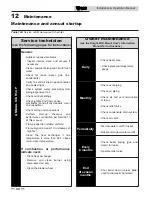
Страница 66: ... manual Flame inspection stable uniform Flame signal at least 10 microamps at high fire Clean the heat exchanger if flue temperature is more than 54 F above return water temperature If combustion or performance indicate need Clean heat exchanger Remove and clean burner using compressed air only Clean the blower wheel ANNUAL START UP Owner maintenance see the Knight Wall Mount User s Information Ma...

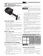
Страница 67: ...he clean out cap on the bottom of the trap Let the condensate and any debris drain out 2 Fill with fresh water until the water begins to pour out of the drain 3 Replace the clean out cap and resume operation Eliminate all system or boiler leaks Continual fresh makeup water will reduce boiler life Minerals can build up in sections reducing heat transfer overheating heat exchanger and causing heat e...

Страница 68: ... valve is inoperative Shut down the boiler until a new relief valve has been installed 2 After following the warning directions in this manual if the relief valve weeps or will not seat properly replace the relief valve Ensure that the reason for relief valve weeping is the valve and not over pressurization of the system due to expansion tank waterlogging or undersizing WARNING WARNING 12 Maintena...

Страница 69: ...the boiler in Section 10 Startup Do not drain the boiler unless it will be exposed to freezing temperatures If using freeze prevention fluid in system do not drain 2 Allow time for the boiler to cool to room temperature if it has been firing 3 Remove the nuts securing the heat exchanger access cover to the heat exchanger and set aside 5 Remove the condensate hose from the heat exchanger end Connec...

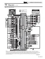
Страница 70: ... SPARK ROD INTEGRATED CONTROL GROUND JUNCTION BOX INTEGRATED CONTROL 120 VAC LOW VOLTAGE HIGH VOLTAGE CAUTION HIGH VOLTAGE SPARK LEAD BLOWER TERMINAL STRIP TERMINAL STRIP CN3 8 CN3 7 CN3 9 CN3 6 CN3 4 CN3 3 CN3 1 CN3 10 DISPLAY CONNECTION BOARD INLET SENSOR OUTLET SENSOR FLUE SENSOR X4 8 X4 7 X4 9 X4 6 X4 4 X4 3 X4 1 X4 10 INTEGRATED CONTROL CN4 11 CN4 12 CN4 10 CN4 4 ALARM CONTACTS RUN TIME CONTA...

Страница 71: ...AUTO RESET HI LIMIT CAUTION HIGH VOLTAGE SPARK LEAD CN5 3 CN5 4 CN5 2 24 VAC COM L N L N L N GND GND GND GND TR1 X8 120 VAC LOW VOLTAGE HIGH VOLTAGE X3 PC INTERFACE CN4 14 CN1 12 CN1 11 CN1 10 CN1 9 CN1 8 CN1 7 CN1 6 CN1 5 CN1 4 CN1 3 CN1 2 CN1 1 Notes 1 All wiring must be installed in accordance with local state provincial and national code requirements per either N E C in USA or C S A in Canada ...

Страница 72: ...6 and sidewall vent termination kit number correction Revision F ECO C03223 reflects edits made to the high altitude section on page 6 Revision G ECO C03735 reflects edits made to the room air LWCO pump pipe sizing chart hydro and dirt separator Revision H ECO C05457 reflects the addition of the illustrations disclaimer on all the piping drawings ECR R02431 changing out dirt separator for Y Strain...

Отзывы: