


Servicing
Diaphragm Vacuum Pumps N 920__.18 and N 920 KT.29.18G
20
Translation of original Operating Instructions, English, KNF 121416-121419 07/18
10. Place the adapter (
14
) onto the pump housing (
15
).
The adapter must be aligned flush with the pump housing (
15
).
This is important for later installation of the diaphragm (
9
).
11. Tighten the two screws (
19
) to hand-tightness.
Begin with the outermost screw and make sure that the adapt-
er (
14
) does not move while you are tightening the screws.
12. Screw the new diaphragm (
9
) into the thread of the stabiliza-
tion diaphragm (
17
) and tighten it by hand.
To ensure proper pump performance, it is important to main-
tain a uniform distance everywhere between the outer edge of
the diaphragm (
9
) and the adapter (
14
). If the distance is not
uniform, you must re-loosen the screws (
19
) and re-align the
adapter so the distance is the same everywhere.
Before you finally tighten the diaphragms, you are recom-
mended to move the diaphragm to the upper dead center by
rotating the fan (
16
).
13. Screw the new diaphragm (
10
) and (
11
) onto the connecting
rods (
12
) and (
13
) and tighten it by hand.
Mount valve plates, intermediate plates and head cover
1. Lay the new O-ring (
18
) on the adapter (
14
).
2. Lay the new valve plates (fig. 7/
4
) and the new O-rings (
5
) on
the intermediate plates (
3
), (
7
)and (
8
).
Upper and lower sides of the valve plates are identical. For
correct position see fig. 6.
3. Lay the new O-ring (
6
) on the intermediate plate (
3
).
4. Place the intermediate plates (
3
), (
7
)and (
8
) on the adapter
(
14
) in the position indicated by the drawing lines.
5. Place the head cover (
1
) on the pump housing (
15
); tighten the
screws (
2
) hand tight, evenly and diagonally.
6. Dispose of the old diaphragms, valve plates and O-rings
properly.
Final steps
1. Reconnect suction and pressure line to the pump.
2. Reconnect the pump to the electricity supply.
If you have any questions about servicing, call your KNF technical
adviser (see last page for contact telephone number).
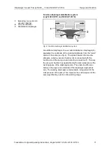
Fig. 7: Position of valve plates
Содержание N920 AP.18
Страница 2: ......
Страница 30: ......
Страница 31: ......
Страница 32: ...KNF worldwide Please find our local KNF partners at www knf com ...


