


Maintenance
Installation Instructions FK 1100
KNF Flodos 178057_MA_FK1100_EN_00.docx
16
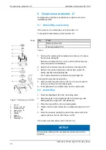
Figure 5: Installing the intermediate
plate
Figure 6: Installing the resonating diaphragm
5.6 Assembling the pump head
Insert the three insert rings (
11
) in the pump housing; see
For easier installation of the diaphragms (
10
), turn the connect-
ing rod to top dead center, beginning with head I. Tighten the
diaphragms well (
10
) by hand. Repeat the steps for heads II
and III.
For head II, press the middle diaphragm (
10
) to bottom dead
center with your thumb.
Place the head plate (
2
) according to Figure 4.
Insert the Cellasto (
3
) and the two O-rings (
4
) into the head
plate (
2
).
Place the resonating diaphragm (
5
) on the head plate (
2
)
according to Figure 6. Make sure that the cut-out in the reso-
nating diaphragm (
5
) and the cams in the head plate (
2
) are
positioned correctly.
Insert the six O-rings (
7
) and anchor valves (
8
) in the connect-
ing plate (
6
) according to Figure 5.
Click the three intermediate plates (
9
) into the connecting plate
(
6
).
Place the connecting plate (
6
) on the head plate (
2
).
Place the complete head on the pump housing. Make sure that
the head sits properly to ensure the desired transfer direction
(direction of arrow).
Insert the eight head screws (
1
) in the head plate (
2
), but
tighten them only slightly for now.
Tighten the four inside head screws (
1
) in a diagonal sequence
by one rotation each.
Tighten the four outside head screws (
1
) in a diagonal se-
quence by one rotation each.
Repeat steps 12. and 13. until all the head screws (
1
) are
tightened to 3.5 Nm. This procedure is important to ensure that
the diaphragm is compressed equally, and the pump is leak-
tight.
Figure 4: Head installation
Содержание FK 1100
Страница 2: ......
Страница 22: ...www knf com ...


