KMX Karts Performane Series Скачать руководство пользователя страница 9

15. 

Select the appropriate seat position referring to the chart below: 


X SEAM 

SEAT POSITION 

36 inch to 38 inch – 91cm to 96cm 

Forward 

38 inch to 40 inch – 96cm to 101cm 

Middle 

40 inch to 44 inch – 101cm to 111cm 

Rear 


16. 

Lower the seat clamp onto the selected seat position on the main frame. Insert the 
two seat clamp bolts from the chain tube side ensuring that there is a plastic spacer 
between the seat clamp and the frame on either side.  Fit the nuts and washers and 
tighten securely.  (Photo 12). 


Photo 12 (Middle position) 


     Photo 13 

 
17. 

Slide the seat stay adjuster rods into the seat stays. Select the 3

rd

 threaded hole and 

screw in the adjuster knobs.  Note:  There is a thread on one side of the slotted end.  
This should be positioned facing inwards.  Locate the rear dropouts into slotted ends 
of the seat stay adjusters.  Secure these with the M6 bolts.   (Photo 13).   

 
18. 

Attach the Seat Covering to the frame with the 8 nuts and bolts provided.  Ensure that 
the seat covering is attached the correct way up.  The top is marked with a sticker. 


19. Front 

Wheel 

Assembly 


FOR BOTH SPORT AND PERFORMANCE MODELS 


NB:  It is important to note that the front wheels are Left and Right hand 
specific.  Each wheel is fitted with a small sticker with either “L” or “R” on it to 
denote this. 

 
Select the correct front wheel for the side you are working on.  Insert the disc into the 
brake calliper and push the axle through the wheel so that the end with the smaller 
thread locates into the hole in the steering pivot.  Fit the 10mm nut and tighten 
securely by inserting the allen key into the outside end of the axle and using a 17mm 
spanner on the nut.  (Photo 14) 
 
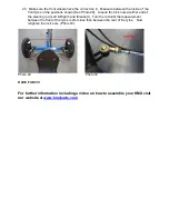
Fit the ½” washer and nut onto the outside thread of the axle and tighten the nut to 
pull in the wheel assembly, then loosen the nut until the wheel spins freely with no 
side movement on the axle.  (Photo 15). 
 
Repeat this process for the opposite side wheel. 
 

Содержание Performane Series

Страница 1: ...Performance Sports Trike Assembly Instructions ...

Страница 2: ...tents 1 0 Introduction 2 0 you need to read this manual 3 0 Your KMX Parts 4 0 Assembly and technical details 5 0 Guidelines for safe use 6 0 Maintenance 7 0 Guarantee conditions 8 0 Guarantee certificate ...

Страница 3: ...on of EN14764 the UK standard for bikes and the CPSC for Bikes in the USA For safety we recommend that an Adult should supervise any child using a KMX Warning Your KMX like bicycles Roller Blades Roller Skates Skateboards Cars Boats or any other moving vehicle can cause injury Exercise caution when riding your KMX Pay attention to street signs be courteous to pedestrians and road users and by all ...

Страница 4: ...ty flag holder 4 Front Boom Clamps 14 Chain and Chain tubes 24 Front chain rings 5 Front wheel pivot bolts 15 Front Wheel Axle Bolt 25 Front Disc brakes 6 Handle Bars 16 Chain pulley 26 Rear Disc brake 7 Front Twist Grip Changer 17 Chain tube spring 8 Rear Twist Grip Changer 18 Rear Wheel 9 Front brake lever 19 Front Wheel 10 Rear brake lever 20 Mudguard ...

Страница 5: ...TEERING 3 Insert the handlebars fully into the handlebar mounts Do not tighten the clamps at this stage Photo 2 4 Attach the left hand track rod end Copy the right hand track rod end for the position of the washers and spacers Photo 3 Photo 3 Photo 4 REAR WHEEL ATTACHMENT 5 Move the rear derailleur to the outside of the frame ensuring that the chain is laid as shown Photo 4 6 Move the disc brake t...

Страница 6: ...clamp provided Photo 6 REAR DERAILLEUR BRAKE 8 Select the highest gear on the right hand handlebar gear changer Place the chain over the smallest rear sprocket and attach the derailleur to the gear hanger using a 5mm allen key Photo 7 Photo 7 Photo 8 9 Attach the rear disc brake using the two M6 bolts Photo 8 ...

Страница 7: ...nce Model 11 PERFORMANCE MODELS Insert the boom into the front frame and attach the pedals Note The left hand pedal has a left hand thread Photo 10 Ensure that the front derailleur and left hand gear changer are in the number 1 position ready to select the smallest front chain ring Feed the cable and the 90 degree aluminium noodle through the slot on the underside of the boom so that the cable and...

Страница 8: ... Run the chain through the front derailleur and around the smallest chain ring and connect the two ends of the chain together with the quick link connector provided Photo 12 NB Ensure that the chain running through the pulley wheel closest to the frame is passing through the derailleur and over the top of the chain ring 14 Seat Assembly FOR BOTH SPORT AND PERFORMANCE MODELS First measure your X se...

Страница 9: ...M6 bolts Photo 13 18 Attach the Seat Covering to the frame with the 8 nuts and bolts provided Ensure that the seat covering is attached the correct way up The top is marked with a sticker 19 Front Wheel Assembly FOR BOTH SPORT AND PERFORMANCE MODELS NB It is important to note that the front wheels are Left and Right hand specific Each wheel is fitted with a small sticker with either L or R on it t...

Страница 10: ... the seat using the bolt washers and nut provided Photo 16 Photo 16 Photo 17 22 If required fit the Flag to the rear wheel axle by first loosening the quick release clamp or axle nut Insert the flag bracket and tighten the clamp or axle nut Photo 17 23 If required fit the Rear Reflector to the Flag Pole and fit the Front Reflector to the underside of the front frame Photo 18 Photo 18 ...

Страница 11: ...all of your foot on the pedal you will have a slight bend at the knee See Photo 19 and 20 Screw in the two boom securing knobs and tighten securely NB Never extend the boom beyond the Stop position mark FOR SPORT MODELS If the boom extends beyond the MAX mark then you will need to add the short chain length supplied Locate the quick link connector in the chain remove this and add the extra chain l...

Страница 12: ...ck nuts at either end of the steering rod Left Right hand threaded Turn the rod until the measurement between the front of the tyres is 2mm less than between the rear of the tyres Now retighten the lock nuts Photo 30 Photo 29 Photo 30 HAVE FUN For further information including a video on how to assemble your KMX visit our website at www kmxkarts com ...

Страница 13: ...ularly See for the correct pressures chapter 3 In case of improper use of your KMX neither the manufacturer nor the dealer can be held responsible The KMX cannot be used near staircases swimming pools or any other water Staircases should be shielded off to avoid riders being able to ride up or down Engage the handbrake button on the rear brake lever to lock the rear brake before leaving the KMX un...

Страница 14: ...ry month or after your KMX gets wet In addition to above Immediately after riding Approx time 30 minutes Dry bike with towel pedal the drive train with your hands while lifting the rear wheel to spin water out of rear bearing surfaces cog set chain etc Wash bike completely with soap and water Dry bike spin wheels and cycle drive train to expel water Apply chain lubricant and wipe off excess Apply ...

Страница 15: ...ions and or not correctly maintained Technical repairs of the KMX are not executed professionally Parts fitted afterwards do not match technical specifications of the KMX or no original KMX parts have been used and or are not fitted correctly Deficiencies due to climate like rust cracks in the rubber or usual weathering of the coatings The KMX is used for rental and or otherwise used by non specif...

Страница 16: ... of Purchase Type KMX Colour Signature buyer GUARANTEE CERTIFICATE KMX Karts COPY Date of Purchase Type KMX Colour Retailer KMX Name Date of Birth Address Town City Postal code Country Signature purchaser Send to KMX Karts Ltd 23 Castle view Rd Portchester PO16 9LA UK ...

Отзывы: