background image

Version 2018-11 
 

Technical Data are subject to change without notice!


Technical Data 


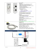
TEL1-PCM-STG-BATT 
Straingage: Full and 1/2 bridge >=350 Ohm, 
Excitation: 4 VDC (fixed) 
Gain: 250; 500; 1000; 2000; 4000; 8000 

(select able from receiver side) 

Gain 

Resolution 

Autozero range 

250 

12 bit 

100% 

500 

12 bit 

200% 

1000 

12 bit 

400% 

2000 

12 bit 

400% 

4000 

12 bit 

400% 

8000 

11 bit 

400% 

Analog signal bandwidth: 0 - 1200 Hz (-3 dB) 
Operating temperature: - 10 to + 80 °C 
Sampling rate 6.944kHz 
Dimensions: 35 x 18 x 12mm (without connectors) 
Weight: 13 grams 
Static acceleration: up to 1000g 
TEL1 PCM BATT Powering: By battery 6-9V 
Power consumption: 70mA  
Housing: splash-water resistant (except the connector pins) 


with female K type thermocouple connector 


with solder pins for thermocouple 


Analog signal bandwidth: 0 - 10 Hz (-3 dB) 
Accuracy: +/-0.5 % (without sensor) 
Operating temperature: - 10 to + 80 °C 
Dimensions: 35 x 18 x 12mm (without th-connector) 
Weight: each module 13 grams (with epoxy resin) 
Static acceleration: up to 3000g


(

housing not filled with epoxy resin) 

Static acceleration: up to 10000g


(housing filled with epoxy resin and without solder pins  


and external capacitor!) 

Powering: Battery with 6-9V, Power consumption: 70mA 

Housing: splash-water resistant IP65  


(except the connector pins)


TEL1-PCM-TH-K - Select Gain 250! 

At Gain 500 multiply the values x2, Gain 1000 with x4 
Max. Voltage output at receiver is +10V! 

°C 

Calibrator  

out (mV) 

Output at receiver (DEC) 

Normal 

(V) 

Min. 

(V) 

Max. 

(V) 

-1.203 

0,06 

0,01 

0,11 

50 

0.820 

0,50 

0,45 

0,55 

100 

2.893 

1,00 

0,95 

1,05 

150 

4.935 

1,50 

1,45 

1,55 

200 

6.935 

1,98 

1,93 

2,03 

250 

8.950 

2,46 

2,41 

2,51 

300 

11.005 

2,98 

2,93 

3,03 

350 

13.090 

3,45 

3,40 

3,50 

400 

15.194 

3,95 

3,90 

4,00 

450 

17.313 

4,46 

4,41 

4,51 

500 

19.441 

4,96 

4,91 

5,01 

550 

21.573 

5,47 

5,42 

5,52 

600 

23.702 

5,99 

5,94 

6,04 

650 

25.822 

6,49 

6,44 

6,54 

700 

27.926 

6,99 

6,94 

7,04 

750 

30.010 

7,49 

7,44 

7,54 

800 

32.072 

7,99 

7,94 

8,04 

850 

34.110 

8,46 

8,41 

8,51 

900 

36.123 

8,94 

8,89 

8,99 

950 

38.110 

9,42 

9,37 

9,47 

1000 

40.072 

9,90 

9,85 

9,95 


Calibrator OMEGA CA71S3, measure at a clamping 
point temperature of 30°C (after 30 min run time) 


Содержание TEL1-PCM-BATT

Страница 1: ...C CM M B BA AT TT T O Op pe er ra at ti in ng g I In ns st tr ru uc ct ti io on ns s D Di ig gi it ta al l T Te el le em me et tr ry y S Sy ys st te em m f fo or r S St tr ra ai in n G Ga ag ge e A Ap pp pl li ic ca at ti io on ns s o on n R Ro ot ta at ti in ng g S Sh ha af ft ts s Gain and Auto Zero setting direct from Receiver Side INSTRUCTIONS FOR QUALIFIED PERSONNEL ONLY ...

Страница 2: ...ibration Overload is indicated by the last LED s in pos or neg direction of the bar graph These OVL LED s operate in peak hold mode and are reset by pressing the overload switch Strain gage sensors 350 Ohm in full and half bridge configuration can be directly connected to the transmitter The excitation is fixed to 4 Volt DC and the gain is set by the gain switch on the receiver side An auto zero A...

Страница 3: ...oxy resin Static acceleration up to 3000g housing not filled with epoxy resin Static acceleration up to 10000g housing filled with epoxy resin and without solder pins and external capacitor Powering Battery with 6 9V Power consumption 70mA Housing splash water resistant IP65 except the connector pins TEL1 PCM TH K Select Gain 250 At Gain 500 multiply the values x2 Gain 1000 with x4 Max Voltage out...

Страница 4: ...wer ON LED Red ON if power switch on Rear side Output to Powerhead via 6pol Tuchel Fuse LED Flashing if fuse is defect Powering 10 30V DC min 24Watt Input via 7pol Tuchel Switch ON OFF Operating temperature 10 to 70 C Dimensions 200 x 105 x 44 without connectors Weight 950 grams Static acceleration upto 200g System accuracy 0 2 measure with gain 1000 350ohm 0 1 full bridge test bridge TEL1 PCM Pic...

Страница 5: ... indicator Strain gage connection Power On LED LED ON Error data transmission LED Flashing Battery voltage lower 6V Reset button of overload indicator AZ button Gain switch The pins for battery e g CR P2 1500mA Use only 6 9V battery Red point pole for battery Positive Baragraph LED With overload indicator Coil depends of shaft diameter 4 25 parallel windings of 0 5 CUL wire see table for help Coil...

Страница 6: ...ata are subject to change without notice 6 Rear Pickup Distance of 5 150mm DC Power cable Power IN DC 10 30V Data input from Pickup and output to Powerhead Power ON OFF switch PCM OUT for Interface Option Flashing if fuse damage ...

Страница 7: ...Version 2018 11 Technical Data are subject to change without notice 7 Pin Connection Note The Powerhead must be fixed in the middle of the coil in a distance from 5 to150 mm ...

Страница 8: ...th 2 layers of mounting tape around the shaft Coil depends of shaft diameter 4 25 parallel windings of 0 5 CUL wires see table for help Solder the wires of the coil on the input pins of TEL1 PCM STG COIL Strip the isolation from the end of the wire with a skinning tool or head up you soldering iron over 450 C to burn off the insulation from the wire ...

Страница 9: ...state of the shaft During the rotation test appropriate safety precautions should be taken The entire installation may be used only by authorized persons By using tape for the attachment it has to be used in the direction of rotation of the shaft and the end has to be secured Only non elastic tapes Fiberglas Tape with high tensile strength should be used for pre fixing Additionally use hose clamps...

Страница 10: ...d the shaft The table standing below will help you to find the right number windings for steel shafts The table below is a help to estimate the number of windings fast To optimize your results you can try one winding more or less Diameter mm Windings 490 4 290 5 190 7 150 9 120 10 80 12 45 16 20 25 Optimum windings for steel shafts 0 100 200 300 400 500 600 0 5 10 15 20 25 30 windings diameter Coi...

Страница 11: ...Use only special lithium Battarys for rotating applications Use only shielded sensor cable When used on rotating shafts all connections must be soldered Mounting of the modules on a shaft must be first fixed with mounting tape only for prefixing and then with additional steel strip ...

Страница 12: ...it den Anforderungen der Normen und Richtlinien fulfills the requirements of the standard and regulations of the Directive satisfait aux exigences des normes et directives 108 2004 EG Elektromagnetische Verträglichkeit EMV EMC DIN EN 61000 6 3 Ausgabe 2002 8 Elektromagnetische Verträglichkeit EMV Teil 6 3 Fachgrundnorm Störaussendung DIN EN 61000 6 1 Ausgabe 2002 8 Elektromagnetische Verträglichke...

Отзывы: