background image

Cooling or heating without reheat

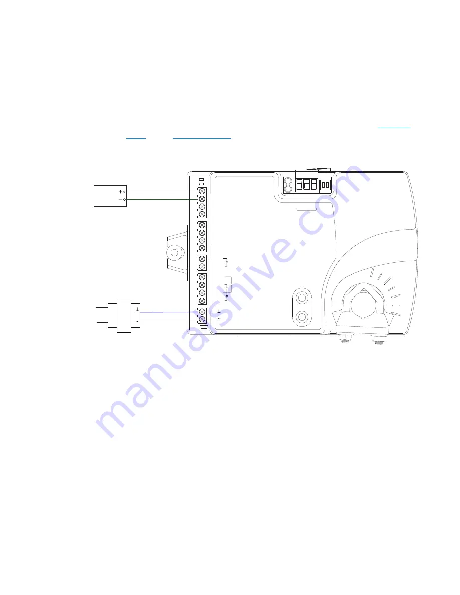
The BAC-8001 is configured for single-duct cooling VAV control without reheat. Connect the
controller as shown in the illustration

Cooling or heating application drawing

on page 42

.

A BAC-8005 or BAC-8205 may also be used for this application.

For cooling and heating, a duct temperature sensor is required for Discharge Air Temperature
limiting and automatic changeover. See the topic

Advanced options

on page 33

for

instructions to enable Discharge Air Temperature limiting.

Submittal sheets for several variations of this application are available from the

BAC-8000

series

page at

KMCControls.com

.

Illustration 6–1 Cooling or heating application drawing

 24 VAC

Duct

Temp

Sensor

ON CTS

1       2

COMM
READY

AI1

AI5

GND

AO4

AO3

SC

BO8

BO5

BO6

SC

BO7

24VAC

AI6

GND

AI7

T

-S
T

A

T

/

SEN

SO

R

-A

+B

S

EO

L

BACnet MS/TP

Section 6: Application drawings

KMC Controls, Inc.

42

Revision H

Содержание SimplyVAV BAC-8001

Страница 1: ...SimplyVAV Application and Installation Guide Revision H ...

Страница 2: ...ed into any language in any form by any means without the written permission of KMC Controls Inc Printed in U S A The material in this manual is for information purposes only The contents and the product it describes are subject to change without notice KMC Controls Inc makes no representations or warranties with respect to this manual In no event shall KMC Controls Inc be liable for any damages d...

Страница 3: ... with configuration 21 Entering system temperature setpoints and limits 23 Configuring the VAV Box options 27 Set the airflow setpoints 29 Advanced options 33 Restore Application 35 Section 5 Balancing airflow 37 Section 6 Application drawings 41 Cooling or heating without reheat 42 Staged reheat 43 Modulating reheat 44 Time proportional reheat 45 Floating reheat 46 Dual duct application 47 Sectio...

Страница 4: ...58 Time proportioned reheat 59 Floating reheat 59 Balancing airflow sequence 60 Dual duct 61 Section 8 System integration and networking 63 Connecting to an MS TP network 63 Connections and wiring 64 End of line termination switches 64 Network bulbs 64 Setting up network communications 65 BACnet objects 67 Input objects 67 Output objects 67 Value objects 68 Loop objects 70 Appendix A K factors 71 ...

Страница 5: ...nnected as a technician s service tool All models are BACnet Application Specific Controllers that are ready to connect to a BACnet MS TP network Device instance MAC address and baud rate are set from an STE 8001 sensor without special software BAC 8001 Model BAC 8001 is supplied with inputs outputs and sequences of operation for the following functions l Single duct heating and cooling VAV l Auto...

Страница 6: ...the topic BACnet objects on page 67 Analog inputs Analog inputs represent BACnet analog input Not all input are applicable or required for all models Key features Standard units of measure Overvoltage input protection Connectors RJ 45 room sensor jack Screw terminals for wire sizes 12 26 AWG Conversion 12 bit analog to digital conversion Input range Passive 10 kΩ pull up to 3 3 volts DC Analog out...

Страница 7: ...ram parameters are stored in nonvolatile memory l Auto restart on power failure Air flow sensor features l Configured as BACnet analog input object l CMOS differential pressure 0 2 inches of water 0 500 Pa measurement range Internally linearized and temperature compensated l Span accuracy 4 5 of reading l Zero point accuracy 0 0008 in H2O 0 2 Pa at 25 C l Barbed connections for 1 4 inch FR tubing ...

Страница 8: ...ing two conditions 1 This device may not cause harmful interference and 2 this device must accept any interference received including interference that may cause undesired operation Installation Supply voltage 24 volts AC 15 20 5 VA 50 60 Hz Weight 13 2 ounces 376 grams Case material Flame retardant plastic Environmental limits Operating 32 to 120 F 0 to 49 C Shipping 40 to 140 F 40 to 60 C Humidi...

Страница 9: ...0 to 24 VAC 50 VA dual hub XEE 6311 100 Transformer 120 277 to 24 VAC 50 60 Hz 96 VA dual hub Sensors STE 8001W80 SimplyVAV sensor and digital display STE 8201W80 SimplyVAV sensor and digital display with motion sensor STE 6010W80 Discrete temperature sensor with RJ 45 connector STE 6014W80 Discrete temperature sensor with rotary setpoint dial RJ 45 connector STE 6017W80 Discrete temperature senso...

Страница 10: ...ilable models The following is a list of SimplyVAV available models Description Models BACnet ASC VAV Cooling Heating only 40 in lbs 90 second actuator BAC 8001 BACnet ASC VAV Fan and Reheat 40 in lbs 90 second actuator BAC 8005 BACnet ASC VAV Dual Duct 40 in lbs 90 second actuator BAC 8007 BACnet ASC VAV Fan and Reheat True damper position 40 in lbs 60 second actuator BAC 8205 Safety consideratio...

Страница 11: ...ts hazards that could result in severe injury or death Caution Caution indicates potential personal injury or equipment or property damage if instructions are not followed Note Notes provide additional information that is important Tip Provides programing tips and shortcuts that may save time SimplyVAV Section 1 About the controllers Revision H 11 ...

Страница 12: ...Section 1 About the controllers KMC Controls Inc 12 Revision H ...

Страница 13: ... 16 Connecting power 17 Maintenance 18 Setting the rotation limits SimplyVAV controllers are manufactured for a damper that rotates 90 degrees from open to close If the VAV damper is not a 90 degree damper set the rotation limits to 45 or 60 degrees before mounting the controller Caution Before setting the rotation limits on the controller refer to the damper position specifications in the VAV con...

Страница 14: ...d or 3 8 to 7 16 inch 9 5 to 11 mm square damper shafts Illustration 2 2 Controls and indicators ON CTS 1 2 COMM READY AI1 AI5 GND AO4 AO3 SC BO8 BO5 BO6 SC BO7 24VAC AI6 GND AI7 T STAT SENSOR A B S EOL BACnet MS TP Status LEDs Mounting tab Mounting bushing Gear clutch button Drive hub and V bolt Mount the controller as follows 1 Manually rotate the damper on the VAV box to the fully open position...

Страница 15: ...ers have preconfigured inputs and outputs to support only the supplied programs and applications l For input and output connection information see the topic Application drawings on page 41 l To connect room temperature sensors see the topic Connecting room temperature sensors on page 15 l To connect a DAT sensor see the topic Connecting a DAT sensor on page 16 l For the BACnet object descriptions ...

Страница 16: ...tion 2 4 Connecting to a sensor Ethernet cable Maximum 75 feet Connecting a DAT sensor The Discharge Air Temperature sensor is required for automatic changeover and for VAV terminal units with reheat Illustration 2 5 Discharge air temperature sensor location DAT sensor Prefered location DAT sensor Changeover only Section 2 Installing the controllers KMC Controls Inc 16 Revision H ...

Страница 17: ...The controllers require a 24 volt AC power source Use the following guidelines when choosing and wiring transformers to the controller l Use a Class 2 transformer of the appropriate size to supply power to the controller l KMC Controls recommends powering only one controller from each transformer l Do not run 24 volt AC power from within an enclosure to external controllers Connect the 24 volt AC ...

Страница 18: ...Maintenance SimplyVAV controllers require no routine maintenance If necessary clean with a damp cloth and mild soap Section 2 Installing the controllers KMC Controls Inc 18 Revision H ...

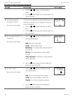
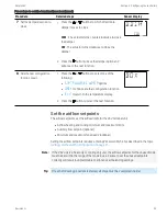
Страница 19: ...the Set Point button to save the value or advance to the next function To enter or change the active setpoints you may need Password 1 Tip Once the following procedure is started all steps must be completed in order Procedure Steps Sensor display 1 Starting display Start from the temperature display 72 12S1 2 Enter Password 1 1 Press any button The display changes to PSW1 2 Press the or buttons to...

Страница 20: ...value The display advances to set the heating setpoint 745 COOLING 4 Set the active heating setpoint 1 Press the or buttons to change the heating setpoint temperature The setpoint changes in increments of 0 5 degrees 2 Press the Set Point button to save the value The display returns to the temperature display 685 HEATING Changing room setpoints continued Section 3 Changing the room setpoint KMC Co...

Страница 21: ...network Users may change the active heating and cooling setpoints without accessing the configuration functions This procedure is covered in the topic Changing the room setpoint on page 19 Note The instructions for the configuration functions cover all of the functions that a digital sensor can set up in the SimplyVAV series of controllers Not all functions are available on every model of controll...

Страница 22: ...display changes to PSW2 2 Press the or button to change the first digit 3 Press the Set Point button to select the next digit Repeat for all four digits 4 When the button is pushed for the fourth correct digit the display changes to COMM Note If Password 2 has not previously been entered the display will change to the CNFG display after Step 1 PSW2 OOOO 3 Select a configuration function Access to ...

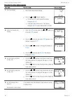
Страница 23: ...be completed in order Procedure Detailed steps Sensor display 1 Start at the temperature display 1 Start at the temperature display 2 Press the and buttons together l If Password 2 is not required the display changes to CNFG l If required enter Password 2 The display changes to CNFG when Password 2 is correct 72 12S1 PSW2 OOOO 2 Select the setpoint display 1 From the CNFG display press the or butt...

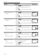
Страница 24: ... occupied 1 Press the or buttons to set the occupied cooling setpoint The setpoint will change in 0 5 increments 2 Press the Set Point button to save the setpoint and advance to the next function Note This setpoint can also be changed as described in the topic Changing the room setpoint on page 19 OCCL 74O 6 Set the occupied heating setpoint This setpoint is used as the active setpoint when the sp...

Страница 25: ...change between heating to cooling 1 Press the or buttons to set the changeover setpoint The setpoint will change in 1 increments 2 Press the Set Point button to save the setpoint and advance to the next function 74 CHNG 10Set the minimum temperature differential setpoint The minimum allowable temperature value between the cooling and heating setpoints 1 Press the or buttons to set the differential...

Страница 26: ...of the following l BOX FLOW ADVC or RSTR options l BACK to choose another configuration function l EXIT to return to the temperature display 2 Press the Set Point button to select the next function STPT Procedure to set the temperature setpoints continued Section 4 Configuring the controllers KMC Controls Inc 26 Revision H ...

Страница 27: ...1 Starting display 1 Start at the temperature display 2 Press the and buttons together l If Password 2 is not required the display changes to CNFG l If required enter Password 2 The display changes to CNFG when Password 2 is correct 72 12S1 PSW2 OOOO 2 Select the box settings display 1 From the CNFG display press the or buttons to show the BOX display 2 Press the Set Point button to select the CNF...

Страница 28: ...e of the following reheat options None Reheat is not enabled Staged Enables staged reheat Modulating The analog reheat output varies from 0 10 volts DC Floating The reheat outputs control a tristate actuator Time proportional A 24 volt triac output controls a thermal wax valve 2 Press the Set Point button to save the reheat option and advance to the next function NONE REHT 6 Set the fan option Not...

Страница 29: ...function BOX Procedure to set the box functions continued Set the airflow setpoints The airflow setpoints set the airflow limits for the VAV terminal unit l Airflow heating and cooling minimum and maximum limits l Auxiliary flow setpoint optional l Minimum and maximum fan speeds optional Setting the airflow setpoints requires entering Password 2 which is described in the topic Getting started with...

Страница 30: ...W The display changes to MNCL CNFG STPT FLOW 3 Set the cooling minimum airflow limit 1 Press the or buttons to set the minimum limit for cooling airflow The setpoint changes in 1 CFM increments 2 Press the Set Point button to save the setpoint and advance to the next function OO MNCL 4 Set the cooling maximum airflow limit 1 Press the or buttons to set the maximum limit for cooling airflow The set...

Страница 31: ...3 S O MXHT 8 Set the minimum limit for fan speed Not used for all models 1 Press the or buttons to set the minimum limit for the fan speed The setpoint will change in 1 increments 2 Press the Set Point button to save the setpoint and advance to the next function 2O MINF 9 Set the maximum limit for fan speed Not used for all models 1 Press the or buttons to set the maximum limit for the fan speed T...

Страница 32: ...buttons to select one of the following l STPT BOX ADVC or RSTR options l BACK to choose another configuration function EXIT 2 Press the Set Point button to select the next function FLOW Procedure to set the airflow setpoints continued Section 4 Configuring the controllers KMC Controls Inc 32 Revision H ...

Страница 33: ...1 Start at the temperature display 2 Press the and buttons together l If Password 2 is not required the display changes to CNFG l If required enter Password 2 The display changes to CNFG when Password 2 is correct 72 12S1 PSW2 OOOO 2 Select the advanced display 1 From the CNFG display press the Set Point button to show the STPT display 2 Press the or buttons to change the display to ADVC 3 Press t...

Страница 34: ...the or buttons to set the time for the standby time The value will change in 1 minute increments 2 Press the Set Point button to save the setpoint and advance to the next function 15 7 Set discharge air temperature limiting Not used for all models Required for reheat 1 Press the or buttons to enable or disable discharge air temperature limiting 2 Press the Set Point button to save the setpoint and...

Страница 35: ...inued Restore Application Choose the RSTR function to reset the SimplyVAV controller to the original configuration and settings Use it also to change the units of measure to display on a SimplyVAV sensor There are two versions of the application program in the controller l The Metric version displays temperature in Celsius and uses metric values for units of measure l The English version displays ...

Страница 36: ...lay to RSTR Caution Choosing RSTR deletes all previously entered values and returns the controller to the manufacturer s settings Only the BACnet communications settings will remain unchanged 4 Press the Set Point button to select RSTR CNFG STPT RSTR 3 Choose the application 1 Press the or buttons to choose ENGLISH or METRIC Metric The sensor displays temperature in Celsius and uses metric values ...

Страница 37: ... setpoints for the unused mode must be set within the range of the mode in use Failure to set the unused setpoints correctly will result in unpredictable or erroneous air balancing settings See Set the airflow setpoints on page 29 for the procedure to adjust the setpoints Note Starting the balancing procedure erases all previous airflow correction factors The airflow readings displayed by the digi...

Страница 38: ...imum airflow even if only one mode is operational Note The airflow displayed by the digital sensor in this stepf is the actual uncorrected airflow 1 Wait for the maximum airflow value to stabilize 2 With a flow hood measure the actual airflow 3 Press the Set Point button to advance to the entry display PMAX stops flashing 4 Press the or buttons to enter the measured airflow 5 Press the Set Point b...

Страница 39: ...duct systems Choosing SEC advances to the SMAX display This is available only on dual duct models l BACK to choose another commissioning function l EXIT to return to the temperature display 2 Press the Set Point button to select the next function PRI SEC 6 Measure and enter the actual maximum secondary airflow The display begins flashing SMAX and also displays the actual airflow at the bottom Note...

Страница 40: ... button to advance to the entry display SMIN stops flashing 4 Press the or buttons to enter the measured airflow 5 Press the Set Point button to save the measured airflow The display advances to SEC SMIN OO 8 Advance or exit 1 Press the or buttons to select one of the following l PRI to balance the primary VAV for dual duct systems l BACK to choose another configuration function l EXIT to return t...

Страница 41: ...ontrol technicians and engineers that will plan for and install controllers for SimplyVAV applications Submittal sheets for all of these applications are available from the BAC 8000 series page at KMCControls com Application drawings in this section Cooling or heating without reheat 42 Staged reheat 43 Modulating reheat 44 Time proportional reheat 45 Floating reheat 46 Dual duct application 47 Sim...

Страница 42: ...scharge Air Temperature limiting and automatic changeover See the topic Advanced options on page 33 for instructions to enable Discharge Air Temperature limiting Submittal sheets for several variations of this application are available from the BAC 8000 series page at KMCControls com Illustration 6 1 Cooling or heating application drawing 24 VAC Duct Temp Sensor ON CTS 1 2 COMM READY AI1 AI5 GND A...

Страница 43: ...utomatic changeover See the topic Advanced options on page 33 for instructions to enable Discharge Air Temperature limiting When connecting the controller to a fan powered VAV unit the fan circuits must be compatible with the following specifications l The fan start circuit is a 24 volt AC pilot duty output l The fan speed output is 0 10 volts DC Submittal sheets for several variations of this app...

Страница 44: ... to enable Discharge Air Temperature limiting When connecting the controller to a fan powered VAV unit the fan circuits must be compatible with the following specifications l The fan start circuit is a 24 volt AC pilot duty output l The fan speed output is 0 10 volts DC Submittal sheets for several variations of this application are available from the BAC 8000 series page at KMCControls com Illust...

Страница 45: ...o enable Discharge Air Temperature limiting When connecting the controller to a fan powered VAV unit the fan circuits must be compatible with the following specifications l The fan start circuit is a 24 volt AC pilot duty output l The fan speed output is 0 10 volts DC Submittal sheets for several variations of this application are available from the BAC 8000 series page at KMCControls com Illustra...

Страница 46: ...charge Air Temperature limiting When connecting the controller to a fan powered VAV unit the fan circuits must be compatible with the following specifications l The fan start circuit is a 24 volt AC pilot duty output l The fan speed output is 0 10 volts DC Submittal sheets for several variations of this application are available from the BAC 8000 series page at KMCControls com Illustration 6 5 Flo...

Страница 47: ... 47 Submittal sheets for several variations of this application are available from the BAC 8000 series page at KMCControls com Illustration 6 6 Dual duct wiring diagram ON CTS 1 2 COMM READY AI1 AI5 GND AO4 AO3 SC BO8 BO5 BO6 SC BO7 24VAC AI6 GND AI7 T STAT SENSOR A B S EOL BACnet MS TP P2 CW COM P1 CCW 24VAC P OUT MOTOR F B POT 24 VAC BAC 8007 TSP 8001 SimplyVAV Section 6 Application drawings Rev...

Страница 48: ...Section 6 Application drawings KMC Controls Inc 48 Revision H ...

Страница 49: ...sors to measure room temperature airflow and discharge air temperature All sensors are automatically detected and the programming is automatically set up for the sensors l SimplyVAV digital wall sensors l STE 6000 series discreet temperature sensors l Discharge air temperature sensor l Airflow sensors and pickups SimplyVAV digital wall sensors The SimplyVAV digital wall sensors include a room temp...

Страница 50: ...nd Changeover on page 53 Airflow sensors and pickups VAV airflow is calculated by measuring the high and low duct pressures with the built in airflow sensor which is connected to airflow pickup tubes The high and low pressure measurements along with the K factor of the VAV terminal unit are used to calculate the airflow through the VAV unit Occupancy sequence A SimplyVAV controller is designed to ...

Страница 51: ...otion sensor the controller starts in STANDBY and changes to OCCUPIED after detecting motion in the space Motion in the space is defined as two movements detected within 5 minutes The controller will change back to STANDBY after a lack a lack of motion for the period specified by the variable Standby Time Standby mode is not valid for controllers without a motion sensor unless commanded by a build...

Страница 52: ...sed when the system is unoccupied Standby setpoint The standby setpoint is used when the controller is in the standby state It is a value calculated from the occupied setpoint and the variable STBY OFFSET The standby offset value is entered by the controls technician during controller setup and system commissioning See the topic Occupancy sequence on page 50 Setpoint limits The programming in the ...

Страница 53: ... Air Available In the heating mode as the Heating Loop increases from 0 to 100 Primary Airflow Setpoint is proportionally calculated between Minimum Heating Airflow and Maximum Heating Airflow See also the topics Changeover on page 53 and Input sources on page 49 Changeover The Discharge Air Temperature input is used by the controller to determine the type of air that is being supplied by the AHU ...

Страница 54: ...ed the controller will lockout reheat control only in the cooling mode The unit will operate this way until a DAT sensor is detected or until the unit is commanded to control to the Active Heating Setpoint by a supervisory BMS If the unit has detected a DAT sensor and DAT Limiting is not enabled the unit s reheat is controlled by the Heating loop instead of the DAT loop See also the topics Changeo...

Страница 55: ...f the following are TRUE 1 l The system mode is OCCUPIED or STANDBY l Either of the Motion Override or Local Override variable objects are TRUE 1 When any of these conditions are no longer true the indicator changes to FALSE 0 NEED HOTTER SUPPLY BV7 The Need Warmer Supply value object is set to TRUE 1 when the system mode is STANDBY or OCCUPIED and the Heating loop is greater than 95 for 30 minute...

Страница 56: ...a series fan any time the Occupancy mode of the controller is set to either OCCUPIED or STANDBY the fan runs continuously The fan speed is set to Maximum Fan Speed when the state is OCCUPIED and set to Minimum Fan Speed when the state is STANDBY When the Occupancy state is UNOCCUPIED the fan starts and runs at minimum speed only on a call for heating The fan starts when the Heating loop is greater...

Страница 57: ...control four types of reheat installations l Modulating reheat l Staged reheat l Time proportioned reheat l Floating reheat All reheat is controlled by either the Heating loop or the Discharge Air Temp Limiting DAT PID loop Loops are described in the topic PID control loops on page 52 l If Discharge Air Temp Limiting is enabled reheat is controlled by the DAT PID loop l If DAT control is not enabl...

Страница 58: ...om temp increase HTG SP 2F HTG SPAN loop 0 100 10 HTG Reheat Staged reheat If the controller is configured for staged reheat it can control up to three stages of reheat through binary triac outputs The reheat outputs are commanded On when the Reheat loop rises above the ON threshold and OFF when the loop drops below the OFF threshold Thresholds are described in the following chart Staged reheat th...

Страница 59: ...ease HTG SP 2F HTG SPAN loop 0 100 10 HTG Reheat Floating reheat If the controller is configured for floating reheat it controls two binary triac outputs to drive the inputs of a tri state actuator connected to a valve If the Reheat loop is less than 30 the valve is driven closed If the loop is greater than 70 the valve is driven open If the loop is in between 30 and 70 no valve action is taken Se...

Страница 60: ...t value of either the cooling or heating maximum airflow setpoints An airflow measurement is made with an airflow hood and the actual airflow value is entered into the controller Once the actual airflow is entered the controller drives the damper closed to the lower value of either the cooling or heating minimum airflow Another measurement is made with the flow hood and that measurement is entered...

Страница 61: ...aximum Flow l As the space temperature falls below the heating setpoint the secondary airflow is modulated from the Heating Minimum flow to the Heating Maximum Flow l Between the heating and cooling setpoints both the primary airflow and secondary airflow are modulated to maintain the Dual Duct Minimum airflow See the topic Dual duct application on page 47 for an application drawing Illustration 7...

Страница 62: ...Section 7 Sequences of operation KMC Controls Inc 62 Revision H ...

Страница 63: ...th SimplyVAV controllers Integration topics Connecting to an MS TP network 63 Setting up network communications 65 BACnet objects 67 Connecting to an MS TP network SimplyVAV controllers are BACnet MS TP compliant controllers Connect them only to a BACnet MS TP network To enter the BACnet device instance MAC address and network baud see the topic Setting up network communications on page 65 Illustr...

Страница 64: ...ation switches The controllers on the physical ends of the EIA 485 wiring segment must have end of line termination added for proper network operation l For controllers at the end of the network set the EOL switches to On l For mid line controllers at the end of the network set the EOL switches to Off Network bulbs SimplyVAVcontrollers include network bulbs located near the MS TP network connector...

Страница 65: ...assword 2 is not required the display changes to CNFG l If required enter Password 2 The display changes to CNFG when Password 2 is correct 72 12S1 PSW2 OOOO 2 Select the CNFG display 1 From the CNFG display press the or buttons to advance to the COMM display 2 Press the Set Point button The display changes to DID CNFG COMM 3 Enter the device instance 1 Press the or buttons to change the first dig...

Страница 66: ...isplay returns to COMM BAUD 384OO 6 Advance or exit 1 Press the or buttons to select one of the following l BLNC or CNFG options l EXIT to return to the temperature display 2 Press the Set Point button to select the next function COMM Procedure to set up network communications continued Section 8 System integration and networking KMC Controls Inc 66 Revision H ...

Страница 67: ...ion AI1 DISCHARGE AIR Discharge Air Temperature KMC 10K Type_III 10K fixed AI2 SPACE SENSOR Space Sensor KMC Type II Deg F 10K fixed AI3 SETPOINT OFFSET Setpoint Offset TABLE 4 10K fixed AI4 PRIMARY DUCT Primary Duct Pressure AI5 SECONDARY DUCT Secondary Duct Pressure Table 8 2 Input objects Output objects The following BACnet output objects represent values at the physical outputs of the controll...

Страница 68: ...um Heating Setpoint AV11 MIN STPT DIFF Minimum Setpoint Differential AV12 STBY OFFSET Standby Offset AV13 MIN COOL FLOW Minimum Cooling Flow AV14 MAX COOL FLOW Maximum Cooling Flow AV15 MIN HEAT FLOW Minimum Heating Flow AV16 MAX HEAT FLOW Maximum Heating Flow AV17 AUXILIARY FLOW Auxiliary Flow AV18 PRI K FACT Primary K Factor AV19 PRI CORR SLOPE Primary Correction Slope AV20 PRI CORR OFFST Primar...

Страница 69: ...ID AV54 MOTOR PAUSE Analog Value 54 AV55 CHNG_OVER_DELAY Cooling Change Over Delay AV56 LOW AUTO OCC Low Limit for Auto Occupy Analog value objects continued Object Name Description BV1 NEED AHU Need For AHU BV2 NEED COLDER SPLY Need For Colder Air Supply BV3 NEED MORE STATIC Need For AHU BV4 LOCAL OVRD Local Override Mode BV5 MOTION OVRD Motion Override Mode BV6 MOTION SENSOR Motion Sensor Wall S...

Страница 70: ...NFIG Fantype Configuration MSV3 REHEAT Reheat Type MSV6 WALL SENSOR Multi state Value 6 Table 8 6 Multistate value objects Loop objects BACnet PID loops are used for modulating the damper and controlling reheat Loop Name Description LOOP1 CL LOOP Cooling Loop LOOP2 HT LOOP Heating Loop LOOP3 DAT Loop Discharge Air Temp Loop Table 8 7 PID control loop objects Section 8 System integration and networ...

Страница 71: ...turer places on the VAV unit If this information is missing and not available from the manufacturer use the K factor in the following chart Duct size in inches K factor CFM K factor LPS 4 265 8 5 357 11 6 460 14 7 652 19 8 890 27 9 1145 34 10 1443 43 12 1972 59 14 2771 86 16 3741 111 24 x 16 6980 208 Table A 1 Start point K factors SimplyVAV Revision H 71 ...

Страница 72: ...Appendix A K factors KMC Controls Inc 72 Revision H ...

Страница 73: ...67 PID loop sequence 52 value 68 balancing procedure 37 sequence 60 baud 65 bulbs network 63 replacement 9 C calibration airflow 37 sensors 33 Celsius display 35 changeover sequence 53 configuration 21 connecting airflow sensor 15 DAT sensor 16 input devices 15 output devices 15 sensors 15 D damper sequence 55 setting direction to close 27 device instance 65 diagnostic indicators 54 discharge air ...

Страница 74: ...ssword 1 19 Password 2 21 PID loops as BACnet objects 70 sequence of operation 52 R reheat configuration 27 floating 46 modulating 44 sequences of operation 57 staged 43 three stage 43 time proportional 45 two stage 43 replacement parts 9 restore application 35 rotation limits 13 S sensors airflow 15 calibration 33 compatible 9 connecting 15 DAT sensor 16 room sensors 15 sequence 49 sequences of o...

Страница 75: ... diagnostic indicators 54 T three stage reheat 43 time proportional reheat 45 timers setting 33 transformer wiring 17 tri state reheat 46 two stage reheat 43 U units to display 35 unoccupied sequence 50 temperature setpoints 23 V value objects 68 W wiring application drawings 41 connecting power 17 DAT sensor 16 MS TP network 63 room sensors 15 SimplyVAV Revision H 75 ...

Отзывы: