PIC Frisbee
www.kitronik.co.uk
Build Instructions
Before you put any components in the board or pick up the soldering iron, just take a look at the
Printed Circuit Board (PCB). The components go in the side with the writing on and the solder goes on
the side with the tracks and silver pads. You will find it easiest to start with the small components and
work up to the taller larger ones. If you’ve not soldered before get your soldering checked after you
have done the first few joints.
Step 1
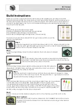
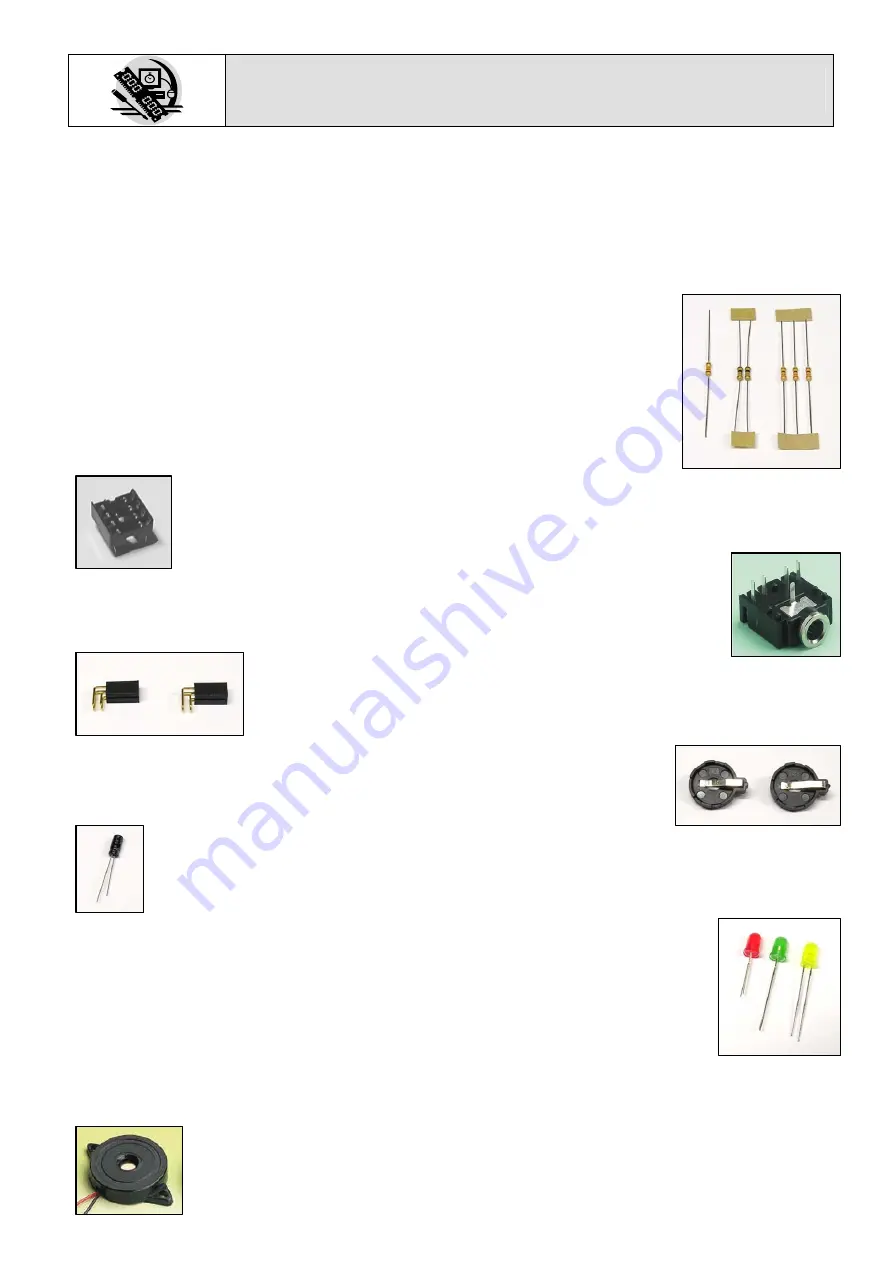
Start with the six small resistors (shown right):
R1& R2 are 10K
Ω
(Brown, Black, Orange coloured bands).
R3 is a 22K
Ω
(Red, Red, Orange coloured bands).
R4, R5 & R6 are 330
Ω
(Orange, Orange, Brown coloured bands).
The text on the board shows where R1, R2, etc go. Make sure that you put the
resistors in the right place.
Step 2
Solder the Integrated Circuit (IC) holder (shown left) in to IC1. When putting this into the
board, be sure to get it the right way around. The notch on the IC holder should line up
with the notch on the lines marked on the PCB.
Step 3
Solder the programming connector (shown right) into the board where it is labeled
‘PROG’.
Step 4
The two tilt switches (shown left) should be soldered into the PCB where it is
labeled SW1 and SW2. Make sure these are inserted the correct way around,
which is indicated by the outline on the PCB.
Step 5
The two battery holders (shown right) should be soldered into the PCB where it is
labeled BAT1 and BAT2. Make sure these are inserted the correct way around,
which is indicated by the outline on the PCB.
Step 6
Solder the electrolytic capacitor (shown left) into the board where it is labeled C1. Make
sure the device is the correct way around. The capacitor has a ‘-’ sign marked on it which
should match the same markings on the PCB.
Step 7
There are three LEDs that are used in the circuit (shown right). These are to be soldered
in to the PCB where it is marked LED1, LED2 and LED3. It doesn’t matter which
coloured LED goes where but it is important that they are inserted the correct way
around. Again this is indicated by the outline on the PCB. The flat edge on the outline
should match the flat on the body of the LED. You may want to stand these LEDs off
the PCB so they are higher than the other components.
Step 8
The PIC can be put into the holder ensuring the notch on the chip lines up with the notch on the
holder.
Step 9 (optional)
The buzzer (shown left) should be soldered into the ‘SOUNDER’ terminal. The red wire
should go to the terminal marked ‘red’ and the black wire should go to the terminal
marked ‘black’.
Содержание PIC Frisbee
Страница 1: ...PIC Frisbee Build Instructions Issue 1 1 ...


