High Power Amp Essentials
www.kitronik.co.uk/2143
How the Amplifier Works
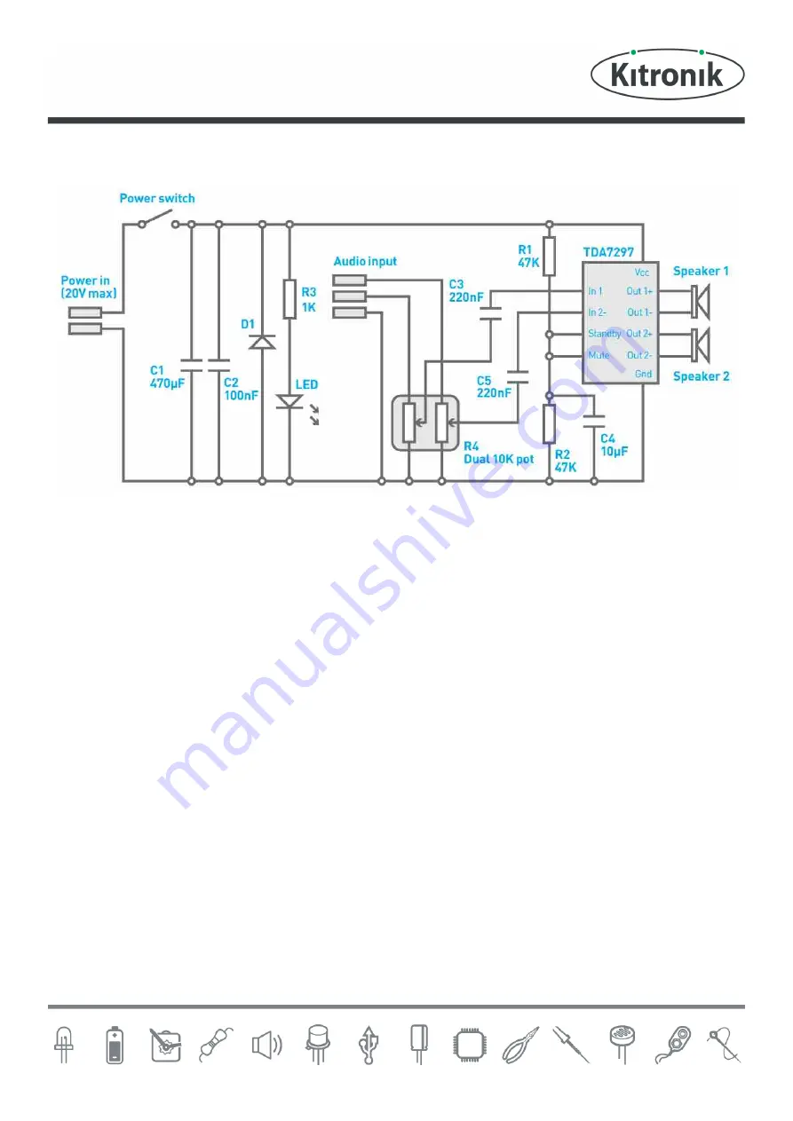
The High Power Ampli®er is a fairly simple circuit as all of the hard work is done by the ampli®er IC. Working from
left to right on the circuit diagram, the power comes into the board and goes through a power switch. When the
power switch is off, this isolates power from the whole circuit. When the switch is on, the LED will light. The
brightness of the LED is set by the resistor R3. The capacitors C1 and C2 are present to ensure that the power supply
to the ampli®er IC is stable. The diode D1 is included so that if the power is connected to the board the wrong way
around, it shorts the power supply. The power supply supplied with the kit instantly cuts the power. This is needed
to protect the audio ampli®er IC.
In the middle of the circuit is the audio input, this is divided down by the dual wipe potentiometer R4, which works
as a volume control. The inputs are de-coupled into the ampli®er IC through the capacitors C3 & C5. In order to
prevent noise on power up, the resistors R1, R2 and the capacitor C4 keep the mute and standby pins in a low state
until the power supply has stabilised. The ampli®er ampli®es both the voltage and the current of the input and this is
then driven into the two speakers.


