background image

9

INSTALLATION INSTRUCTIONS - FREESTANDING GAS RANGE

Check ignition of oven burners.

The operation of oven igniters should be checked after
range and supply line connectors have been carefully
checked for leaks and range has been connected to
electric power. Be sure all packing materials and
literature are removed from oven.

The oven burner is equipped with an electric control
system as well as an electric oven burner igniter. If your
model is equipped with an upper oven burner, it will also
have an electric burner igniter. These control systems
require no adjustment. When the oven is set to operate,
current will flow to the igniter. It will "glow" similar to a light
bulb. When the igniter has reached a temperature sufficient
to ignite gas, the electrically controlled oven valve will open
and flame will appear at the oven burner. There is a time
lapse from 30 to 60 seconds after the thermostat is turned
ON before the flame appears at the oven burner. When the
oven reaches the set temperature, the glowing igniter will
cycle off. The burner flame will turn off in 20 to 30 seconds
after the igniter turns off. To maintain any set oven
temperature, this cycle will continue as long as the oven
control is set to operate.

To check oven burner ignition:

a.

Set oven to 

Bake


at 300ºF

. See User's Manual for

operating instructions.

b.

Within 60 seconds the oven burner should ignite.
Check for proper flame, and allow the burner to cycle
once. Reset control to 

OFF

.

c.

If your model is equipped with a waist-high broiler, set
oven to

 Broil

. See User's Manual for operating

instructions.

d.

Within 60 seconds the broil burner should ignite.
Check for proper flame. Reset control to

 OFF

.

Burner flame size

5/8"

Cooktop

Check ignition of surface
burners.

Operation of electric igniters should be checked after range
and supply line connectors have been carefully checked for
leaks and range has been connected to electric power.

a.

To check for proper ignition, 

push in and turn

 a

surface burner knob 

counterclockwise

 to the 

LITE

position. You will hear the igniter sparking.

b.

The surface burner should ignite when gas is available
to the burner. Purge air from supply lines by leaving
knob in the 

LITE

 position until burner ignites. Each

burner should light within four (4) seconds in normal
operation after air has been purged from supply lines.

c.

Visually check that burner has a flame. Once the
burner ignites, the control knob should be turned out
of the LITE position.

d.

Try each surface control knob separately until all
surface burners have been checked. Each burner
location is equipped with a separate electrode.

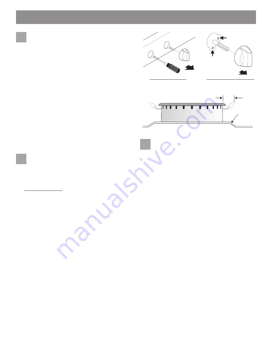
Adjust the LOW setting of surface
burner valves (linear flow).

Test  to verify if LOW setting should be adjusted:

a.

Push in and turn control to LITE until burner ignites.

b.

Push in and quickly turn knob to lowest position.

c.

If burner goes out, reset control to OFF.

d.

Remove the surface burner control knob.

For all burner styles (except Dual or Twin burner):

e.

Insert a thin-bladed screwdriver into the hollow valve
stem and engage the slotted screw inside. Flame size
can be increased or decreased with the turn of the
screw. Turn counterclockwise to increase flame size.
Turn clockwise to decrease flame size. (See Figs. 17
& 19).

Adjust flame until you can quickly turn knob from LITE
to lowest position without extinguishing the flame.
Flame should be as small as possible without
extinguishing.

For Dual or Twin burner style adjustment only:

e.

The inner portion (Simmer) of the twin burner flame
size can be increased or decreased with the turn of
screw A. Use screw B to adjust the flame size of the
outer portion of the Twin Burner (See Fig. 18). Turn
the screw counterclockwise to increase flame size.
Turn clockwise to decrease flame size. Adjust flame
size until you can quickly turn the knob from LITE to
lowest position without extinguishing the flame.

Note: Air mixture adjustments are not required on surface

burners.

for Dual or Twin burner only

other surface burners

A

B

Fig. 17

Fig. 19

7

8

9

Fig. 18

Содержание KGRS206XSS

Страница 1: ...ge Remove all packing material from the oven compartments before connecting the gas and electrical supply to the range Observe all governing codes and ordinances Be sure to leave these instructions with the consumer Important notes to the consumer Keep these instructions with your Use Care Guide for future reference Be sure your range is installed and grounded properly by a qualified installer or ...

Страница 2: ...ER FAILURE RESET ALL OVEN CONTROLS TO OFF IN THE EVENT OF A POWER FAILURE The electric ignitor will automatically re ignite the oven burner when power resumes if the oven thermostat control was left in the ON position When an electrical power failure occurs during use the surface burners will continue to operate During a power outage the surface burners can be lit with a match Hold a lighted match...

Страница 3: ...rials you will need Pipe joint sealant that resists action of LP Propane gas Fig h Gas line manual shut off valve Fig i A new flexible metal appliance conduit 1 2 NPT x 3 4 or 1 2 I D must be design certified by CSA International Because solid pipe restricts moving the range we recommend using a new flexible conduit 4 to 5 foot length for each new installation and additional reinstallations Fig j ...

Страница 4: ...in the wall or floor where the range is to be installed must be sealed 2 7 Recommended area for 120V outlet on rear of wall and area for thru the wall connection of pipe stub and shut off valve 18 Min to cabinets on either side of range 30 30 Min height from cooktop to cabinets 25 24 15 23 36 Std 30 11 1 2 Installation beside wall If installing beside a wall the minimum distance to combustible wal...

Страница 5: ...alled and does not allow the bracket to fit flush against wall remove molding or mount bracket to floor For wall mount Fig 4 locate the bracket by placing the back edge of the template against rear wall and the side edge of template on the mark made referencing the side of the range Place bracket on top of template and mark location of the screw holes in wall If rear of range is further than 1 1 4...

Страница 6: ...re regulator to LP Propane use Care must be taken during installation of range not to obstruct the flow of combustion and ventilation air For proper operation the maximum inlet pressure to the regulator should be no more than 14 inches of water column pressure The inlet pressure to the regulator must be at least 1 inch greater than regulator manifold pressure Example If regulator is set for natura...

Страница 7: ...east two 2 other top burners burning Be sure the gas supply inlet pressure is at least one inch above specified range manifold pressure The gas supply pressure should never be over 14 water column When properly adjusted for Natural Gas the manifold pressure is 4 For LP Propane Gas the manifold pressure is 10 c Tighten the gas supply fitting and or appliance conduit to flare union adaptor on the ri...

Страница 8: ...er cap placement Fig 14 Incorrect burner cap placement Fig 15 Check burner cap placement It is very important to be sure that all surface burner caps and burner grates are properly installed and in the correct locations before operating the appliance Please note that the burner heads are secured to the cooktop The cooktop is not removeable Do not attempt to remove or lift the cooktop To prevent fl...

Страница 9: ...to electric power a To check for proper ignition push in and turn a surface burner knob counterclockwise to the LITE position You will hear the igniter sparking b The surface burner should ignite when gas is available to the burner Purge air from supply lines by leaving knob in the LITE position until burner ignites Each burner should light within four 4 seconds in normal operation after air has b...

Страница 10: ... about your range always be sure to include the model and serial numbers and a lot number or letter from the identification plate on your range Your identification plate also tells you the rating of the burners the type of fuel and the pressure the range was adjusted for when it left the factory Adjust air shutter lower oven To determine if the oven burner flame is proper remove the oven bottom pa...

Страница 11: ...ble celui ci ne doit pas excéder 0 91 m 3 pi de longueur Un robinet de gaz manuel en T doit être installé à la conduite de gaz qui est branchée à cet appareil MESURESDESÉCURITÉIMPORTANTES L installation de cette cuisinière doit être faite conformément aux codes locaux ou si ce type de code n existe pas au code national sur le gaz combustible ANSI Z223 1 dernière édition si l appareil est installé ...

Страница 12: ...é reviendra si les commandes du thermostat du four ont été laissées à ON marche Lorsqu une panne d électricité survient durant l utilisation les brûleurs de surface continueront de fonctionner Durant une panne d électricité les brûleurs de surface peuvent être allumés au moyen d une allumette Pour ce faire tenez une allumette allumée près du brûleur puis faites tourner lentement le bouton à la pos...

Страница 13: ...e d alimentation en gaz fig i Conduite flexible neuve en métal pour appareil électroménager 1 3 cm 1 2 po de NPT x 1 9 cm 3 4 po ou 1 3 cm 1 2 po de diam int approuvée par CSA International Étant donné que les tuyaux rigides empêchent la cuisinière de bouger nous recommandons l utilisation d une conduite flexible neuve mesurant de 121 9 cm à 152 4 cm 4 pi à 5 pi pour chaque nouvelle installation o...

Страница 14: ...ère et emplacement de la connexion murale du tuyau et du robinet d arrêt manuel 18 po Distance minimale entre les armoires de chaque côté de la cuisinière 30 po 15 po 23 po 36 po Std 11 1 2 po Installation contre un mur Si l appareil est installé contre un mur la distance minimale qui sépare le mur combustible d une cuisinière dotée d une hauteur de 91 1 cm 36 po et plus dépend de la capacité nomi...

Страница 15: ...upport sur le dessus du gabarit et faites des marques sur le mur pour indiquer à quel endroit seront insérées les vis Si l arrière de la cuisinière se trouve à plus de 3 2 cm 1 1 4 po du mur lorsqu elle est installée fixez le support au plancher voir fig 5 SU PP OR T AN TI RE NV ER SE ME NT Pour effectuer le montage sur le plancher installez le support en plaçant le bord arrière du gabarit à l end...

Страница 16: ...ombustion et à la ventilation n est pas obstrué Pour assurer le bon fonctionnement de la cuisinière la pression d admission maximale allant vers le détendeur ne doit pas dépasser 35 6 cm 14 po par rapport à la colonne d eau La pression d admission allant vers le détendeur doit être supérieure d au moins 2 5 cm 1 po à la pression au collecteur du détendeur Exemple Si le détendeur est réglé à une pr...

Страница 17: ... la pression du collecteur La pression de l alimentation en gaz ne doit jamais être supérieure à 35 6 cm 14 po à la colonne d eau La pression au collecteur est de 10 2 cm 4 po lorsque celle ci est ajustée de façon appropriée pour le gaz naturel Pour le gaz propane GPL la pression au collecteur doit être de 25 4 cm 10 po c Serrez le raccord d alimentation en gaz ou la conduite de l appareil en le b...

Страница 18: ...ositionnementdu chapeaudebrûleur Il est très important de vérifier que tous les chapeaux et toutes les grilles des brûleurs de surface sont correctement installés et se trouvent au bon endroit avant d utiliser l appareil Veuillez noter que les têtes des brûleurs sont fixées à la table de cuisson La table de cuisson n est pas amovible N essayez pas de soulever ou d enlever la table de cuisson Pour ...

Страница 19: ...raire des aiguilles d une montre et mettez le à la position LITE allumage Vous entendrez alors l allumeur produire des étincelles b Le brûleur de surface devrait s allumer lorsque le gaz se rend à son niveau Faites sortir l air qui se trouve dans les conduites d alimentation en laissant le bouton à la position LITE allumage jusqu à ce que le brûleur s allume Chaque brûleur devrait s allumer en l e...

Страница 20: ...pièces ou que vous désirez obtenir des renseignements à propos de votre cuisinière assurez vous de toujours inclure le numéro de série et le numéro de modèle ainsi que la lettre ou le numéro de lot inscrits sur la plaque signalétique de votre cuisinière La plaque signalétique donne également de l information sur la capacité des brûleurs le type de gaz à utiliser et la pression à laquelle la cuisin...

Отзывы: