background image

2

-- NOTES --

43

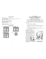
MODEL SPECIFIC TABLES

KEYPAD MATRIX

8268477

MODEL

NO.

PRESSURE

SWITCH

DISPENSER

RINSE

AID

SENSOR

RINSE

AID

HARNESS

WIRING

HARNESS

8269996

8269189

8269190

8269191

KUDS01DJ

KUDS01IJ

KUDR01TJ
KUDM01TJ

KUDI01TJ

N/A

N/A

N/A

MODEL

NO.

KUDS01DJ

KUDS01IJ

KUDR01TJ
KUDM01TJ

KUDI01TJ

8269200 (Top)

8269201 (Front)

8269199
8269198
8269197
8269196

USER

INTERFACE

JUMPER

TAILS

INTERCONNECT

CARD

NUMERIC

DISPLAY

PUMP &

MOTOR

ASSMEBLY

8269202

8269207

8269206

8268422

N/A

N/A

N/A

Содержание KAD-7

Страница 1: ...TECHNICAL EDUCATION KUD01 STAINLESS STEEL DISHWASHER JOB AID 4317288 KAD 7 48 Inc For the way it s made ...

Страница 2: ... technician to properly diagnose malfunctions and repair the KUD01 Stainless Steel Dishwasher The objectives of the Job Aid are The service technician will Understand proper safety precautions Successfully troubleshoot and diagnose malfunctions Successfully perform necessary repairs Successfully return the dishwasher to proper operational status TO THE INSTRUCTOR INDEPENDENT STUDENT This Job Aid i...

Страница 3: ...4 ACCESSING COMPONENTS INSIDE THE TUB 17 SERVICING THE SUMP ASSEMBLY 20 Section Four TROUBLESHOOTING AND DIAGNOSIS 25 TROUBLESHOOTING CHART 25 COMMON CYCLE TIME CHART 27 HOW TO USE COMMON CYCLE TIME CHART 28 COMMON CYCLE TIME CHART NOTES 32 RAPID ADVANCE FEATURE DIAGNOSTIC CYCLES 36 DIAGNOSTIC CYCLE TIME CHART 37 Section Five TECH TIPS 39 WIRING DIAGRAM 39 STRIP CIRCUITS 40 ELECTRONIC CONTROL CONN...

Страница 4: ...brackets are snapped into the metal ridge on which the cabinet seal is installed Fig 5 2 Press Here Press Here Top of Console Cabinet Seal Support Collar 3 Open the door The unsnapped latch strike will remain attached to the door catch and will be pulled out of the mount ing slots in the support collar Fig 5 3 Cabinet Seal Removed Mounting Slots Top of Console Fig 5 2 Fig 5 3 4 Remove the latch st...

Страница 5: ...hose water supply and electrical wiring is critical The tub must be level Reduced water consump tion of this dishwasher requires that it be installed level and plumb for proper water recirculation back into the sump area during operation Do not remove the drain tube from the left side of the tub If the loop is removed the dishwasher will not initiate Automatic Purge Filtration The drain tube also ...

Страница 6: ...HARNESS 8269996 8269189 8269190 8269191 KUDS01DJ KUDS01IJ KUDR01TJ KUDM01TJ KUDI01TJ N A N A N A MODEL NO KUDS01DJ KUDS01IJ KUDR01TJ KUDM01TJ KUDI01TJ 8269200 Top 8269201 Front 8269199 8269198 8269197 8269196 USER INTERFACE JUMPER TAILS INTERCONNECT CARD NUMERIC DISPLAY PUMP MOTOR ASSMEBLY 8269202 8269207 8269206 8268422 N A N A N A ...

Страница 7: ...EK OF MANUFACTURE PRODUCT SEQUENCE NUMBER F K 36 50001 MODEL NUMBER DESIGNATOR Model Serial Number Plate Left side of frame behind door MODEL NUMBER INTERNATIONAL SALES OR MARKETING CHANNEL K KITCHENAID BRAND PRODUCT IDENTIFIER PD Convertable Potable UD Undercounter FEATURE LEVEL I J M P R S SERIES CONFIGURATION FEATURES YEAR OF INTRODUCTION J 2000 COLOR CODE WH White GR Graphite BT Biscuit AL Alm...

Страница 8: ...rips also invoke Automatic Purge Filtration APF events during the Pre Wash and Wash Periods See APF description on page 5 First Fill Water Temperature The duration of the Quick Cleanup cycle may be modified based upon the water temperature of the first fill If the thermistor senses water temperature of 135 F or higher the electronic control will elimi nate the second wash function The Quick Cleanu...

Страница 9: ...sor switch closes indicat ing to the electronic control that high soil levels are present The electronic control invokes the APF feature in specific intervals of the Pre Wash and Wash peri ods Up to five intervals are available to enable APF events As many as three APF events may occur in any one of these intervals however APF events will be spaced no less than one minute apart APF operates for a ...

Страница 10: ... a new cycle To Clear the Indicators Press Cancel Drain before starting the dishwasher to clear all options and cycles CHANGING A CYCLE During the first fill of a cycle 1 Press a new cycle and or options 2 Check the detergent dispensers They must be filled properly for the new cycle After the first fill of a cycle 1 Press The display shows The dishwasher starts a two minute drain if needed Let the...

Страница 11: ...me to the cycle In the Normal cycle this high temperature rinse sanitizes the dishes and glassware in accor dance with the NSF International requirements 95 480 05 2480 NOTE The Baked On Cookware cycle automatically uses this option Sani Rinse is an option with Heavy and Normal Wash Energy Saver Dry Select this energy saving option to dry without heat Air drying is useful when loads contain plasti...

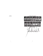
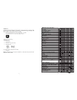
Страница 12: ... Start again 1 8 Diagnostic Cycle Time Chart INTERVAL CYCLE LED s ANTI BACTERIA COOKWARE POTS PANS HEAVY NORMAL CHINA QUICK CLEANUP TIME SAVER RINSE ONLY CANCEL DRAIN OPTION LED s P SCOUR H T SCRUB SOAK OPTION NO HEAT DRY AIR DRY E SVR DRY SANI RINSE DELAY 2 HR DELAY 4 HR DELAY 8 HR RINSE AID EMPTY NOTE 1 LOCKOUT CYCLE PROG STATUS LED s W1 W2 WASHING W3 R1 CIRC R2 a k a WASHING on some models RINS...

Страница 13: ...wing option keys in the sequence shown will either start the Diagnostics Cycle or turn on the Rapid Advance feature for stepping through customer selectable cycles HIGH TEMP SCRUB ENERGY SAVER DRY HIGH TEMP SCRUB ENERGY SAVER DRY Or SANI RINSE ENERGY SAVER DRY SANI RINSE ENERGY SAVER DRY Note HIGH TEMP SCRUB POWER SCOUR HIGH TEMP SCOUR Note AIR DRY NO HEAT DRY ENERGY SAVER DRY If the above key seq...

Страница 14: ...ormal cycle The control stops washing and turns all loads off except the vent in these intervals The intent is to let the existing energy in the wash water on the dishes soften and loosen the food soil The Soaking and Soaking Sensing indicators are turned on during these intervals see note 7 NOTE 10 PULSED DRY CHINA CYCLE ONLY The China cycle on all models turns the heater off in intervals 1 3 and...

Страница 15: ...ned on during all thermal hold intervals to signal that cycle timing display sequencing and numeric cycle time display countdown operations have been suspended or frozen while the water is heated to the proper temperature see note 3 NOTE 7 SOAKING SENSING SOAKING STATUS INDICATORS In general the Soaking Sensing indicator is primarily a sensing indicator and is turned on during cycles whenever the ...

Страница 16: ... and quantity limits APF purges must be spaced at least 60 seconds apart within any given APF interval the pressure switch will be ignored prior to 60 seconds The maximum number of APF purges allowed within a given APF interval is specified on the time chart in that interval the pressure switch will be ignored for the duration of an APF interval once the maximum APF limit for that interval has bee...

Страница 17: ...ed in interval 42 the control continues with the heavy soil version of the cycle Note Energy Star models have a different light soil non sensor version of the Normal cycle than other models see Model Specifics table to identify Energy Star models Note Models without pressure switches soil sensors never get sensor trips and thus always default to the light non sensor version of the cycle and never ...

Страница 18: ...The solid and shaded bars to the right indicate the potential use of cycle indicators and loads by at least one cycle variation Fig 4 4 Wash Motor should be running CYCLE PROGRESSION STATUS INDICATORS PROG BAR W1 PROG BAR W2 WASHING PROG BAR W3 PROG BAR R1 CIRC PROG BAR R2 This LED will be labeled as WASHING on models that use it but it is on during all Wash and Rinse Periods RINSING DRYING SOAKIN...

Страница 19: ...pecific time lengths The length of these intervals is deter mined by input from the thermistor Fig 4 3 If the thermal cap temperature is not reached in a predetermined length of time the electronic con trol will proceed to the next interval See Note 3 page 33 In the same row as the Cycle Name the shaded or solid bars indicate all possible intervals that may be used in that cycle All clear interval...

Страница 20: ...me Chart reproduced on page 27 of this Job Aid can be found on the Tech Sheet supplied with each dishwasher The Tech Sheet is located behind the access panel at the bottom of the unit The Common Cycle Time Chart appears to be more complex than a typical Esterline Chart This is a result of the greatly expanded number of cycles and cycle variations possible with electronic controls as opposed to pre...

Страница 21: ...bly to the inner door liner Fig 3 8 4 Bend the two locking tabs at the top and bottom of the dispenser assembly up away from the dispenser body 5 The dispenser assembly can now be lifted from the inner door liner Fig 3 8 Fig 3 7 SERVICING COMPONENTS INSIDE THE TUB Removing the Inner Feed Tube and Lower Spray Arm The Inner Feed Tube is held in place by two 2 metal clips Fig 3 9 One is located on th...

Страница 22: ...ve the grille Fig 3 13 2 The water inlet can now be separated from the dishwasher tub Fig 3 12 Rear Feed Cap Water Inlet Servicing the Heating Element The heating element Fig 3 14 should not be re moved unless it has failed All critical components of the dishwasher can be removed without remov ing the heating element If the heating element must be removed it must be replaced with a new one When in...

Страница 23: ...inals Removing the Overfill Assembly 1 Remove the toe and access panels from the bottom of the dishwasher 2 Tip the float slightly and gently toward the back of the tub and lift up to disengage it from the overfill assembly body Fig 3 15 3 Remove the standpipe nut 4 Push the overfill assembly through the bottom of the tub 5 Open the cover and lift the overfill control switch from the assembly 6 Di...

Страница 24: ...e of the pump assembly Fig 3 19 SECTION FOUR TROUBLESHOOTING AND DIAGNOSIS TROUBLESHOOTING CHART PROBLEM POSSIBLE CAUSES CORRECTION TEST Dishwasher does not run or stops during a cycle Dishwasher will not fill Dishwasher will not drain Dishwasher will not dry dishes 1 Door is not latching properly 2 Child lock is ON 3 Wash Cycle not set properly 4 Household fuse blown or circuit breaker tripped 5 ...

Страница 25: ...etween the volute and sump Use a small amount of rinse aid on the volute seal to help installation Fig 3 24 page 22 Fig 3 20 Drip Shield Inset Bolt Holds Drip Shield in Place NOTES 4 With the wash motor removed the separation screen can be removed from the sump base Fig 3 21 5 The thermistor can be removed from the sump by turning it turn counterclockwise and pulling it out Fig 3 22 The thermistor...

Страница 26: ... valve located between the wash motor and the drain can be removed with a pair of needle nose pliers Fig 3 30 NOTE When replacing the check valve simply drop it in place The inlet protector will seat the flapper valve properly when it is reinstalled Check Valve Removing the Impeller from the Wash Motor The impeller is attached to the wash motor and can be removed once the wash motor is removed fro...

Отзывы: