

True Sinewave Power Inverter
SW1204 SW2405 SW1204i SW2405i
MW1204 MW1204i
Owner’s Manual
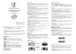
Picture shown SW1204i-EU
.
For safe and optimum performance, the Power Inverter must be used properly. Carefully read
and follow all instructions and guidelines in this manual and give special attention to the
CAUTION and WARNING statements.
PLEASE KEEP THIS MANUAL FOR FUTURE REFERENCE
Disclaimer
While every precaution has been taken to ensure the accuracy of the contents of this guide,
KISAE Technology assumes no responsibility for errors or omissions. Note as well that
specifications and product functionality may change without notice.
Important
Please be sure to read and save the entire manual before using your KISAE Power Inverter.
Misuse may result in damage to the unit and/or cause harm or serious injury. Read manual
in its entirety before using the unit and save manual for future reference.
Product Numbers
Modified Sinewave MW Series:
120V model
MW120412V 400W 120VAC Modified Sinewave Inverter (US - NEMA 5-15)
230V model
MW1204i-EU12V 400W 230VAC Modified Sinewave Inverter
(Schuko - CEE 7/4)
MW1204i-UK12V 400W 230VAC Modified Sinewave Inverter
(British - BS1363)
MW1204i-AU12V 400W 230VAC Modified Sinewave Inverter
(Australia - NS/NZS 3112)
True Sinewave SW Series:
120V model
SW1204 12V 400W 120VAC True Sinewave Inverter (US - NEMA 5-15)
SW2405 24V 500W 120VAC True Sinewave Inverter (US - NEMA 5-15)
230V model
SW1204i-EU12V 400W 230VAC True Sinewave Inverter
(Schuko - CEE 7/4)
SW1204i-UK12V 400W 230VAC True Sinewave Inverter
(British - BS1363)
SW1204i-AU12V 400W 230VAC True Sinewave Inverter
(Australia - NS/NZS 3112)
SW2405i-EU24V 500W 230VACTrue Sinewave Inverter
(Schuko - CEE 7/4)
SW2405i-UK24V 500W 230VAC True Sinewave Inverter
(British - BS1363)
SW2405i-AU24V 500W 230VAC True Sinewave Inverter
(Australia - NS/NZS 3112)
Service Contact Information
Email: [email protected]
Phone:
1-877-897-5778
Web:
www.kisaetechnology.com
1. INTRODUCTION
Thank you for purchasing the KISAE Power Inverter. With our state of the art, easy to use
design, this product will offer you reliable service for providing AC power for your home, cabin,
RV or Trailer. The KISAE Power Inverter can run many AC-powered appliances when you
need AC power anywhere.
This manual will explain how to use this unit safely and effectively. Please read and follow
these instructions and precautions carefully.
IMPORTANT SAFETY INFORMATION
This section contains important safety information for the KISAE Power Inverter. Each time,
before using the KISAE Power Inverter, READ ALL instructions and cautionary markings on or
provided with the inverter, and all appropriate sections of this guide.
The KISAE Power Inverter contains no user-serviceable parts. See Warranty section for how
to handle product issues.
WARNING: Fire and/or chemical burn hazard
• Do not cover or obstruct any air vent openings and/or install in a zero-clearance compartment.
WARNING: Failure to follow these instructions can result in death or series injury
• When working with electrical equipment or lead acid batteries, have someone nearby in case
of an emergency.
• Study and follow all the battery manufacturer’s specific precautions when installing, using
and servicing the battery connected to the inverter.
• Wear eye protection and gloves.
• Avoid touching your eyes while using this unit.
• Keep fresh water and soap on hand in the event battery acid comes in contact with eyes. If
this occurs, cleanse right away with soap and water for a minimum of 15 minutes and seek
medical attention.
• Batteries produce explosive gases. DO NOT smoke or have an open spark or fire near the
system.
• Keep unit away from moist or damp areas.
• Avoid dropping any metal tool or object on the battery. Doing so could create a spark or
short circuit which goes through the battery or another electrical tool that may create an
explosion.
WARNING: Shock Hazard. Keep away from children!
• Avoid moisture. Never expose unit to snow, water etc.
• Unit provides household AC, treat AC output sockets the same as regular wall AC sockets at
home.
WARNING: Explosion hazard!
• DO NOT use the KISAE Power Inverter in the vicinity of flammable fumes or gases (such as
propane tanks or large engines).
• AVOID covering the ventilation openings. Always operate unit in an open area.
LIMITATIONS ON USE
Do not use in connection with life support systems or other medical equipment or devices.
2. PRODUCT
DESCRIPTION
The KISAE Power Inverter package includes the items list below.
• Power Inverter base unit
• Owner’s manual
• DC Input cable accessory
3. INSTALLATION
WARNING: KISAE Technology recommends that all wiring be done by a certified technician or
electrician to ensure adherence to the applicable electrical safety wiring regulations and
installation codes. Failure to follow these instructions can damage the unit and could also
result in personal injury or loss of life.
CAUTION: Before beginning your power inverter Installation, please consider the following:
• The Power Inverter base unit should be used or stored in an indoor area away from direct
sunlight, heat, moisture or conductive contaminants.
• When placing the unit, allow a minimum of three inches of space around the unit for optimal
ventilation.
Understanding the unit
features
Material Prepare for Installation
Typical Wiring block diagram of the Power Inverter:
Battery Bank:
• The use of deep cycle battery is highly recommended for power inverter application
• For battery size, you need to identify how long you wish to operate the load(s). KISAE does
recommend that you purchase as much battery capacity as possible. See more on
“Estimated Run time and Load” in Section 4.
• Please use 12V Battery Bank system for 12V DC Input Inverter (SW1204, MW1204,
SW1204i and MW1204i series). Use 24V Battery Bank system for 24V DC Input Inverter
(SW2405 and 2405i series). Using 12V DC Input Inverter on 24V Battery System will
damage the inverter and may caught fire.
Fuse or Circuit Breaker:
• DC-rated fuse or DC-rated circuit breaker connected along the DC positive line is required.
• Select a fuse or circuit breaker with 60A/16V minimum rating for the 12V DC Input Inverter(s)
and 35A/ 30V minimum rating for the 24V DC Input Inverter(s).
• Based on the size of the battery bank chosen on the 12V or 24V Battery Bank system above,
determine the overall short circuit current rating of the battery bank from the battery
manufacturer. The fuse or circuit breaker chosen has to be able to withstand the short circuit
current that may be generated by the battery bank.
Disconnect Switch:
• Select a Disconnect Switch with the same or higher rating of the selected fuse or circuit
breaker from the above.
• The Disconnect Switch is used to disconnect the DC power between the power inverter and
the battery bank during service, maintenance or trouble shooting.
DC Input Cable:
• Use of low resistance wire is required for all the DC connections between the inverter and
the battery bank.
• Uses minimum #8 AWG wire with maximum cable length of 5 feet for 12V DC Inverter
system and #10 AWG wire for 24V DC Inverter system.
Installing the Power Inverter System
WARNING: Electrical Shock Hazard
The unit ‘On/Off’ switch does not disconnect the DC power from the battery. Use the DC
Disconnect Switch or disconnect the DC input cables connection to disconnect the DC power
from the battery before working on any circuits connected to the unit. Failure to follow these
instructions can result in death or serious injury.
CAUTION: Unit Damage
Reversing the battery connection to the DC Input terminals will damage the unit and it cannot
be repaired. Damage caused by reverse polarity connection is not covered by the warranty.
Power Inverter Installation (All except MW series)
• Choose an appropriate mounting location.
• For indoor use, the orientation of the unit can be mounted in any direction except with the
DC Input panel facing upwards or downwards.
• Use mounting template below to mark the positions of the mounting screws. Drill the 4
mounting holes and place the inverter in position and fasten the inverter to the mounting
surface.
Power Inverter DC Input Connection:
• Connect one end of the negative DC input cable to the Power Inverter DC negative terminal
(black).
• Connect the other end of the negative DC input cable to the battery negative terminal.
• Make sure the Disconnect Switch is in the OFF position.
• Connect one end of the positive DC input cable to the Inverter DC positive terminal (red).
• Connect the other end of the positive DC input cable to one of the terminals of the
Disconnect Switch.
• Connect a DC input cable between the other terminal of the Disconnect Switch and one side
of the terminal of the fuse holder.
• Connect a DC input cable between the other terminal of the fuse holder and the battery
positive terminal.


