


.
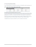
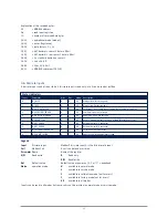
A.4 Holding registers
Device Control
PDU address Parameter
R/W
Type
Mode Description
34
IO_DEF_SCALE_FACTOR
R/W
S16
All
Default scale factor
35 to 40
Factory use only
A.5 Read input register
Many of the registers and controls are for remote diagnostics. In this chapter only the most interesting registers and controls
are described.
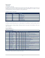
Register 0
IO_DEVICE_TYPE
The device type defines which device is connected. This register can be used to check the type of the connected device.
IO_datamodel_version 102 supports the following type of sensors.
46
Real-time Processed Data
Parameter name
Register R/W
Initial Val
Mode
Description
IO_DEVICE_TYPE
R0
R
65535
All
Selected device type of the sensor
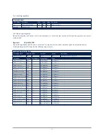
Parameter
Value
# of sensors 1/Sensitivity
Type
SMP3
(volt version)
601
1
5-20 µV/(W/m²)
Pyranometer
SMP3
(current loop version)
602
1
5-20 µV/(W/m²)
Pyranometer
SMP6
(volt version)
619
1
7-14 µV/(W/m²)
Pyranometer
SMP6
(current version)
620
1
7-14 µV/(W/m²)
Pyranometer
SMP10
(volt version)
617
1
7-14 µV/(W/m²)
Pyranometer
SMP10
(current version)
618
1
7-14 µV/(W/m²)
Pyranometer
SMP11
(volt version)
603
1
7-14 µV/(W/m²)
Pyranometer
SMP11
(current loop version)
604
1
7-14 µV/(W/m²)
Pyranometer
SMP21
(volt version)
605
1
7-14 µV/(W/m²)
Pyranometer
SMP21
(current loop version)
606
1
7-14 µV/(W/m²)
Pyranometer
SMP22
(volt version)
607
1
7-14 µV/(W/m²)
Pyranometer
SMP22
(current loop version)
608
1
7-14 µV/(W/m²)
Pyranometer
SGR3
(volt version)
609
2*
5-15 µV/(W/m²)
Pyrgeometer
SGR3
(current loop version)
610
2*
5-15 µV/(W/m²)
Pyrgeometer
SGR4
(volt version)
611
2*
5-15 µV/(W/m²)
Pyrgeometer
SGR4
(current loop version)
612
2*
5-15 µV/(W/m²)
Pyrgeometer
SHP1
(volt version)
613
1
7-14 µV/(W/m²)
Pyrheliometer
SHP1
(current loop version)
614
1
7-14 µV/(W/m²)
Pyrheliometer
SUV5
(volt version)
615
1
300 - 500 µV/(W/m²)
UV Radiometer
SUV5
(current loop version)
616
1
300 - 500 µV/(W/m²)
UV Radiometer
.
Register 1
IO_DATAMODEL_VERSION
The data-model describes the functions supported by the smart sensor. This document is valid for data-model version: ‘102’.
A different implementation of the Modbus® protocol (with new features) could result in a different data model ‘that is’ or ‘that
is not’ compatible with the older version.
The value of this register must be >=102. If you receive another value then you should read an older or newer version of this
document and check the differences.
Register 2
IO_OPERATIONAL_MODE
The operation mode defines the state of the smart sensor. The operational modes are 1 = Normal Mode, 2 = Service Mode, 3 =
Calibration Mode, 4 = Factory Mode and 5 = Error mode. The standby mode (mode 0) is not supported.
After power on the operation mode (1) is set. When the
IO_CLEAR_ERROR is set then the smart sensor always returns to the
normal mode. When the Error mode (5) is set, then there is a fatal error.
Register 3
IO_STATUS_FLAGS
This register defines the status of the smart sensor and the validity of the data. Each bit has a special meaning. Bit 0 is the first
(least significant) bit.
Bit 0
Quality of the signal
see IO_VOID_DATA_FLAG
Bit 1
Overflow
see IO_OVERFLOW_ERROR
Bit 2
Underflow
see IO_UNDERFLOW_ERROR
Bit 3
Error flag
see IO_ERROR_FLAG
Bit 4
ADC Error
see IO_ADC_ERROR
Bit 5
DAC Error
see IO_DAC_ERROR
Bit 6
Calibration Error
see IO_CALIBRATION_ERROR
Bit 7
Update EEPROM error
see IO_UPDATE_FAILED
Register 4
IO_SCALE_FACTOR
The scale factor defines the number of fractional digits, the range and the position of the decimal point for the following
registers:
IO_SENSOR1_DATA, IO_SENSOR2_DATA, IO_RAW_SENSOR1_DATA and IO_RAW_SENSOR2_DATA. The scale factor is read
only. The default value of the scale factor is set during calibration mode or it can be changed during operation (see register
IO_DEF_SCALE_FACTOR and coil IO_AUTO_RANGE).
If the register
IO_SCALE_FACTOR is not set to 0 then you must multiply or divide the data of register (X), whereas X is one of the
above mentioned registers.
Scale factor = 2
(floating point) result = (integer) register (X) / 100.0
Scale factor = 1
(floating point) result = (integer) register(X) / 10.0
Scale factor = 0
(floating point) result = (integer) register(X)
Scale factor = -1
(floating point) result = (integer) register(X) * 10.0
The default value of register
IO_SCALE_FACTOR is 0. However, this value can be set to a different value if the coil IO_AU-
TO_RANGE is set or a different value is written to the register IO_DEF_SCALE_FACTOR (set default scale factor).
Содержание SGR series
Страница 1: ...SGR series Smart Pyrgeometer Instruction Manual...
Страница 2: ...2...
Страница 4: ...4...
Страница 6: ...6...
Страница 22: ...22...
Страница 24: ...24...
Страница 26: ...26...
Страница 32: ...32...
Страница 38: ...38...
Страница 40: ...40...
Страница 42: ...42...
Страница 57: ...57...


