


11
compound such as Loctite 515. Temporary gaskets may be
fabricated from plastic sealing compound but these should
not be made too thick since the material may be squeezed
into the equipment.
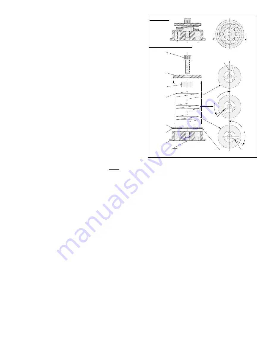
DISCHARGE VALVES
If the cause of poor pump vacuum is not due to leaks or oil
contamination, the next step is to inspect the discharge valves
(see Figure 5). The discharge valves are located at the exhaust
port of each chamber. They should not cause trouble unless they
are mechanically damaged or are prevented from sealing properly
due to foreign matter on the valve seat Under normal pump
usage, the valves should be replaced annually. When the pump is
operating at blank-off without gas ballast, a sharp hydraulic noise
(click) indicates proper valve operation.
The poppet type valve has six flat, washer-like springs which press
against a sealing disk. The disk fits against a seal forming a tight
seal. The springs are maintained in place by a lift stop and the
entire valve is held together by a capscrew. The valves are attached
to the cylinder by means of screws and a hold-down plate.
To inspect the discharge valves, proceed as follows:
1. Drain oil from the pump and remove the separator housing
cover.
2. Unscrew the air/oil separator from the top of the valve deck
cover.
3. Remove the capscrew ive, scoop the oil out of the valve cavity
with a small container. Remove cap screws in valve hold down
plates and lift out valve plates with valves. NOTE: Absence of
oil in this chamber is an indicator of discharge valve leakage.
4. Inspect the valves by snapping the valve disk or lower valve spring away from the valve seat to check for spring tension and
mechanical defects. Inspect the sealing surfaces for dirt or other foreign material. Check that the disk or lower valve spring has
not warped (dish shape) as they must be flat for full contact. If a more careful inspection is required, remove the cap screw(s)
holding the valve together. When reassembling the valve, replace valve components in exactly the same position as before.
SHAFT SEAL ASSEMBLY
Under normal conditions, the shaft seal has a long trouble-free life. It may become worn or scratched on the sealing face by dirty
sealing oil which also lubricates the shaft seal, or it may be damaged by excessive heat due to poor lubrication.
If oil drips from the shaft seal and bearing housing, it is an indication that the shaft seal should be inspected, and replaced as
necessary. The drain plug of the shaft seal and bearing housing should be removed as long as oil is leaking past the shaft seal. If
oil, which has leaked from the shaft seal, is allowed to drain through the bearing it will wash the grease from the bearing and cause
it to fail.
To inspect the seal, proceed as follows:
1. Remove the pump panels and belts.
2. Remove the pump pulley and drive key from the shaft.
3. Remove the shaft bearing and housing. (a) Remove the outboard bearing retainer nut from the shaft. (b) Remove the
capscrews holding the bearing housing and remove it.
4. Inspect the face of the running surface for dirt, scratches, or grooves which might cause leaks into the pump. A smooth shining
carbon face indicates a good seal. A crease across the sealing ring, a dent, or scratch in the running face makes a direct leak
through the seal. Cracks or hardening of the rubber parts indicate that they were exposed to excessive operating temperatures
and need replacement.
ASSEMBLY
ASSEMBLY PROCEDURE
CAP
SCREW
LIFT
STOP
LIFT
SPACER
SPRING
DISC
SEAT
ASSEMBLE
CONCAVITY
FACING ‘SEAT’
APPLY ‘LOCTITE’ TO THREAD
OF ITEM 60. AREA UNDER ITEM
50 ‘DISC’ REMAIN CLEAN
120°
GUIDE
GUIDE
GUIDE
No individual component sales. Discharge valves are sold as an assembly only.
3RD PAIR
2ND PAIR
1ST PAIR
120°
Figure 5. Discharge Valve
Содержание KT VFP Series
Страница 16: ...16 KT 840VFP KT 1350VFP FINAL PUMP ASSEMBLY ...
Страница 18: ...18 KT 840VFP KT 1350VFP MAIN PUMP ASSEMBLY ...
Страница 20: ...20 KT 840VFP KT 1350VFP OIL MIST ELIMINATOR ...