King-Meter Digital II-LCD Скачать руководство пользователя страница 2


Contents 


Preface ............................................................................................... 1 
Appearance and Size ......................................................................... 2 

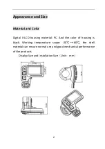
Material and Color .................................................................... 2 

Function Summary and Button Definition ........................................ 3 

Function Summary .................................................................... 3 
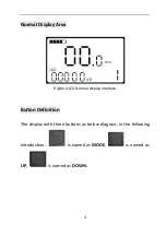
Normal Display Area .................................................................. 4 
Button Definition ....................................................................... 4 

Operation Cautions ........................................................................... 5 
Installation Instruction ...................................................................... 5 
Standard Operation ........................................................................... 6 

Power On/Off ............................................................................ 6 
Display Interface ........................................................................ 6 
Walk Assist ................................................................................. 7 
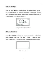
Turn on Backlight ....................................................................... 8 
PAS level Selection..................................................................... 8 
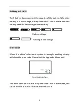
Battery Indicator........................................................................ 9 
Error code .................................................................................. 9 

Users Setting .................................................................................... 10 

Preparation before Starting up ............................................... 10 
General Setting ........................................................................ 10 
Trip Distance and Trip Time Clearance .................................... 10 
Backlight Brightness ................................................................ 11 
Exit Setting ............................................................................... 11 
Password Setting ..................................................................... 11 

Содержание Digital II-LCD

Страница 1: ...KING METER USERS GUIDE Digital II LCD English ...

Страница 2: ...4 Operation Cautions 5 Installation Instruction 5 Standard Operation 6 Power On Off 6 Display Interface 6 Walk Assist 7 Turn on Backlight 8 PAS level Selection 8 Battery Indicator 9 Error code 9 Users Setting 10 Preparation before Starting up 10 General Setting 10 Trip Distance and Trip Time Clearance 10 Backlight Brightness 11 Exit Setting 11 Password Setting 11 ...

Страница 3: ...ver Current Cut Setting 18 Pedal Assist Sensor Setting 19 The Direction of Pedal Assist Sensor Setting 19 The Sensitivity of PAS Sensor Setting 19 PAS Sensor Proportion Parameter Setting 20 Speed Sensor Selection 20 Throttle Function Setting optional 21 Throttle Walk Assist Enable Disable optional 21 Throttle Vector Enable Disable optional 21 System Setting 22 Delay Time Setting of Battery Power 2...

Страница 4: ... Quality Warranty and Coverage 27 Circuit Block Diagram 28 Software Version 29 Appendix 1 Error Code 30 Appendix 2 Password Table 30 Appendix 3 Personalized Parameter Setting 31 Continue Appendix 3 32 Appendix 4 Pedal Assist Proportion default value 33 ...

Страница 5: ...tal II LCD product introduction carefully before using it We will use the brief words to inform you of all the details including hardware installation setting and normal use of the display when using our display Meanwhile the introduction will also help you solve possible confusion and barriers ...

Страница 6: ...olor Digital II LCD housing material PC And the color of housing is black Working temperature scope 20 60 the shell material can ensure normal use and good mechanical performance of the products Display Size and Installation Size Unit mm ...

Страница 7: ...y of functions and showing to meet your requirements Battery indicator Speed Including real time speed Max speed and Average speed Distance Including single Trip distance ODO Trip time Walk assist Turn on Backlight Error code Multiple parameter setting Recover default parameter setting ...

Страница 8: ...Normal Display Area Digital II LCD Normal display interface Button Definition The display with three buttons as below diagram in the following introduction is named as MODE is named as UP is named as DOWN ...

Страница 9: ...do not tear off the stickers to avoid water infusion Please do not modify system parameters to avoid parameter disorder Make the display repaired immediately when not working properly Installation Instruction Fix the display on the handlebar adjust the angel Plug the two connectors from display and controller when off power supply ...

Страница 10: ...play no longer uses the battery s power supply leakage current is less than 1uA If do not use E bike for more than 10 minutes the display will turn off automatically Display Interface After turning on display it shows real time speed Shortly press MODE to switch speed information showing as real time speed unit Km h average speed unit Km h Max Speed unit Km h real time speed Real time speed Averag...

Страница 11: ... trip time ODO unit KM ODO Single trip Single trip time Walk Assist Press and hold DOWN to start walk assist status The bike will keep at an even speed output 6km h Release the button to exit walk assist status The screen shows walk mode flashing symbol Walk Assist Interface Walk assist can only be working when you push the bike and please do not start this function when riding ...

Страница 12: ...D backlight when lack of light or riding in night Hold UP for 2 seconds again LCD backlight turns off Backlight and headlight interface PAS level Selection Press UP or DOWN to change the output power of the motor The power ranges from level 1 to level 5 Level 1 is the minimum power Level 5 is the maximum power The default value is level 1 PAS level interface ...

Страница 13: ...battery needs to be recharged immediately Battery voltage Flashing at low voltage Error code When the e bike s electronic system is wrongly working display will show the error code Please find the Appendix 1 for detail Error Code Interface The error interface can exit only when the fault is eliminated the E bike will not continue to drive after the failure ...

Страница 14: ... bike General Setting Press MODE button to start the display then hold both UP and DOWN for 2 seconds to enter the setting menu Trip Distance and Trip Time Clearance TC means trip distance clearance Press UP or DOWN to choose Y or N Y means to clear the trip distance Trip distance and trip time will be cleared at the same time ...

Страница 15: ...e the modification and exit the general setting Password Setting Hold both UP and DOWN for 2 seconds to enter normal setting interface Then hold both UP and MODE for 2 seconds to enter power on password setting On the screen shows P 2 this requests to input power on password UP and DOWN is to change the number and MODE is to select digit one by one After the 4 digits inputted press MODE to confirm...

Страница 16: ... press MODE to confirm and enter Password modify interface y Power on Password Enable n Power on Password Disable Password enable interface Password Modification PS means password UP and DOWN is to change the number and MODE is to select digit one by one finally to hold MODE to confirm the modification and exit the setting state ...

Страница 17: ...rameter setting On the screen shows P 1 this requests to input permission password UP and DOWN is to change the number and MODE is to select digit one by one finally press MODE to confirm In case password correct enter the Power on password enable setting interface otherwise stays at the password interface Hold MODE to exit The permission password is 0512 Using parameter setting interface ...

Страница 18: ...er into Speed limit setting Speed Limit Setting LS means limit speed The maximum riding speed of factory default of display is 25km h Changing the value can set max riding speed of E bike when E bike exceeds set value the controller will stop powering the motor to protect rider s safety The optional range of maximum speed setting is 12km h 40km h Shortly press UP or DOWN to adjust limited speed pa...

Страница 19: ...ut Hold both UP and DOWN for more than 2 seconds to enter normal setting then hold both UP and DOWN again to enter into personalized parameter setting interface On the screen shows P 3 this requests to input permission password UP and DOWN is to change the number and MODE is to select digit one by one finally press MODE to confirm In case password correct enter the Power on password enable setting...

Страница 20: ...one Take the first voltage for example 1 on the screen means the first voltage 28 0 means the first battery voltage value Press UP DOWN to select the value and MODE to confirm and enter into next voltage setting After all 5 voltages set hold MODE to confirm and turn back to personalized parameter setting interface Battery indicator voltage setting interface ...

Страница 21: ...ion interface Pedal Assist Ratio Modification To modify the value of Pedal assistant ratio will meet the different requirements Take the level 1 for example 30 50 percent is the recommended range 40 is the present value i e 40 output Press UP DOWN to select shortly press MODE to confirm and enter into the next Pedal assistant ratio setting After all inputted hold MODE over 2 seconds to confirm the...

Страница 22: ... 0A to 18 0A Press UP DOWN is to change the value of the current and hold MODE to confirm the setting and turn back to personalized parameter setting interface 15A is the default value of controller over current cut Current setting interface Depending on the hardware of controller some controller may not reach the set value 18A ...

Страница 23: ...s MODE to confirm and turn to PAS sensitivity setting The default direction is forward Direction of Pedal assistant sensor setting The Sensitivity of PAS Sensor Setting SCN means the sensitivity of PAS and 2 to 9 can be selected 2 is strongest 9 is the weakest UP DOWN is to select sensitivity value and MODE is to confirm selection and turn to Pedal assist sensor ratio setting SCN default value is ...

Страница 24: ...ack to personalized parameter setting interface Proportion parameter of PAS Speed Sensor Selection SPS means Speed sensor It can be set according the magnet head number on the e bike wheel Press UP DOWN to select the quantity of magnet head the range is from 1 to 9 and hold MODE to confirm and turn to personalized parameter setting interface SPS default value is 1 Speed Sensor Selection ...

Страница 25: ...e Hold MODE to confirm the selection and turn back to personalized parameter setting interface HL default value is N Throttle Enable Disable setting Throttle Vector Enable Disable optional HND means throttle HF Y means throttle vector enable HF N means throttle vector disable If HF Y is selected when turning the throttle the maximum output of the motor can only reach the speed of corresponding PAS...

Страница 26: ...sable interface System Setting Delay Time Setting of Battery Power DLY means delay time of battery power Choose delay time 3 6 12s through pressing UP DOWN then shortly press MODE to confirm and enter the max speed limit setting The default time is 3s Delay time of battery power interface Max Speed Limit Setting MAX SPD means max speed limitation Set the max speed when ...

Страница 27: ...etting parameter is the upper limit specified by the display manufacturer Button Walk Assist Enable Setting PUS means button pushing walk assist Press UP DOWN to choose Y N Y means enable and hold DOWN to run at walk assist mode N means disable Shortly press MODE to confirm and enter into Push walk assist speed setting The default value is Y Button Walk Assist Enable Setting ...

Страница 28: ...ress MODE to confirm and enter into Slowly start up setting Default value is 25 i e the output is 25 Interface of walk assist speed setting Slowly Start up Setting SSP means slowly start up The scope is 1 4 4 means the slowest Press UP DOWN to choose Hold MODE to confirm and turn back to personalized parameter setting interface The default value is 1 Interface of slowly start up setting ...

Страница 29: ...current setting If there is no operation in one minute display will automatically exit the setting state Recover Default Setting DEF means recover default Hold both UP and MODE for more than 2 seconds to enter the default setting interface Pressing UP DOWN to select Y or N Y means to recover default setting And permission password is required to recover default setting The permission password is 0...

Страница 30: ...password interface In the recovery default battery power ODO and trip cannot be recovered but starting up password can be recovered FAQ and Questions Q Why the display is not able to start up A Check the connector between display and controller Q How to deal with the error code A Send it to the maintenance place immediately ...

Страница 31: ...r display out of the factory Ⅱ Other items The following items do not belong to our warranty scope 1 The shell is disassembled 2 The connector is broken 3 Shell is broken or scratched after the display delivered out of factory 4 Lead wire is broken or scratched 5 Failure or damage caused by force majeure such as fire earthquake etc or natural disasters like lighting etc 6 Beyond Warranty period ...

Страница 32: ...D 4 green RX Receiving data 5 yellow TX Transmitting data Notes some displays are with waterproof cables wires hidden inside the wire cover Table 2 Standard connector cable sequence display with throttle Standard sequence Wire color Definition 1 red VCC Power 2 blue K Power of controller 3 black GND Gnd 4 green RX Receiving data 5 yellow TX Transmitting data 6 white ZB Throttle signal data ...

Страница 33: ...29 Software Version This operating instruction is general purpose software version V1 0 Some version of the e bike LCD may have slightly difference which should depend on the actual use version ...

Страница 34: ...blem 24 Motor Hall defect 25 Brake Failed 30 Abnormal Communication Appendix 2 Password Table No Display Password Setting 1 0512 Using parameter setting password fixed 2 Default 1234 Starting up password changeable 3 2962 Personalized parameter setting password fixed 4 0368 Recovery setting password fixed ...

Страница 35: ...g No Setting Display Details 1 Battery power Five battery power value 2 PAS level PAS level option PAS level proportion 3 Current limit Limit current 4 PAS sensor PAS sensor direction PAS sensor sensitivity 5 Speed sensor Speed sensor magnet No ...

Страница 36: ...play Details 6 Throttle function Throttle walk assist enable setting Throttle vector enable setting 7 System setting Time delay of battery Max speed setting Button walk assist enable setting Walk assist speed setting Slowly startup setting ...

Страница 37: ...33 Appendix 4 Pedal Assist Proportion default value Level Level Item 1 2 3 4 5 6 7 8 9 0 3 1 3 47 72 92 0 5 1 5 15 33 50 66 100 0 7 1 7 35 46 57 68 79 90 97 0 9 1 9 25 34 43 52 61 70 79 88 96 ...

Страница 38: ...34 KING METER ...

Отзывы: