COMPRESSOR CONTROLS
ADDITIONAL REGULATORS AND CONTROLS
Since the air tank pressure is usually greater than that which is needed, an
air pressure regulator is employed to control the air pressure ahead of any
individual driven device. Seperate air transformers which combine the
function of air regulation, moisture and dirt removal should be used where
applicable.
OPERATION CONTROLS
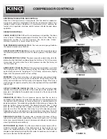
CHECK VALVE (A) FIG.7.
When the air compressor is operating, the check
valve is “open”, allowing compressed air to enter the air tank. When the air
compressor reaches its “Cut-Out” pressure, the check valve “closes”,
allowing air pressure to remain inside the air tank.
TANK PRESSURE GAUGE (A) FIG. 8.
The tank pressure gauge indicates
the reserve air pressure in the tank.
ON/AUTO-OFF SWITCH (B) FIG.8.
Turn this switch ON to provide power to
the automatic pressure switch and OFF to remove power at the end of each
use.
PRESSURE SWITCH (C) FIG.8.
The pressure switch automatically starts the
motor when the tank pressure drops below the factory set “Cut-In” pressure.
It also stops the motor when the air tank pressure reaches the factory set
“Cut-Out” pressure.
ASME SAFETY VALVE (D) FIG. 8.
If the pressure switch does not shut off
the air compressor at its cutout pressure setting, the safety valve will protect
against high pressure by “popping out” at its factory set pressure (slightly
higher than the pressure switch cut-out setting).
WARNING!
: If the safety valve does not work properly, over pressurization
may occur, causing air tank rupture or an explosion. Daily pull the ring on the
safety valve to make sure that the safety valve operates freely. If the valve is
stuck or does not operate smoothly, it must be replaced with the same ASME
type of valve.
OUTLET PRESSURE GAUGE (E) FIG. 8.
The outlet pressure gauge
indicates the air pressure available at the outlet side of the regulator. The
pressure is controlled by the regulator and is always less than or equal to the
tank pressure.
REGULATOR (F) FIG.8.
The air pressure coming from the air tank is
controlled by the regulator. To unlock the regulator, pull it outwards then turn
the regulator knob clockwise to increase pressure or counterclockwise to
decrease pressure. To avoid minor readjustment after making a change in the
pressure setting, always approach the desired pressure from a lower
pressure. When reducing from a higher to a lower setting, first reduce the
pressure less than that desired, then bring it up to the desired pressure.
Depending on the air requirements of each particular accessory, the outlet
regulated air pressure may have to be adjusted while operating the accessory.
DRAIN VALVE (A) FIG.9.
The drain valve is located at the base of the air
tank and is used to drain condensation at the end of each use. Turn drain
valve lever counterclockwise to open (no pressure build-up) or clockwise to
close it (permits pressure build-up).
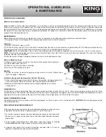
MOTOR RESET (A) FIG.10.
The Wisconsin Electric motor comes with an
automatic overload protector. If the motor draws to much power for any
reason, the overload protector will shut off the motor. The motor must be
allowed to cool before restarting. Wait for motor to cool down, once motor is
cool, press the reset button and restart.
FIGURE 7
FIGURE 8
FIGURE 9
FIGURE 10

