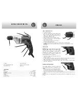


GETTING TO KNOW YOUR TOOL
1
. Trigger
2.
Forward/Reverse Switch
3.
Keyless Chuck
SPECIFICATIONS
Model ...........................................................................................................................8304N
Chuck size ........................................................................................................3/8” (Ø10mm)
Amperage ...........................................................................................................................5A
No load speed (RPM) ..................................................................................0-3,000 (variable)
Voltage ............................................................................................................................120V
Cycle/Phase .....................................................................................................60Hz, 1 phase
Insulation class ............................................................................................................Double
4.
Lock-on Button
5.
Power on indicator light
6.
Belt clip
3
2
1
6
5
4
FIXING & CHANGING DRILL BIT
•
Turn the Drill off first.
•
Clean the shivers and any other foreign objects
away from the bit and chuck, otherwise the bit
might not be tightened securely and thus will
induce severe personal injuries.
•
Hold the ring (2) and turn the sleeve (1) jaws.
•
Insert the bit into the chuck, make sure that the
bit is in as far as it will go.
•
Hold the ring (2) firmly and turn the sleeve (1)
clockwise to tighten the chuck.
•
To remove the bit, hold the ring (2) and turn the sleeve (1) counterclockwise.
WARNING!
More than 1/3 of the general length of the drill bit must protrude out of the
chuck jaws.
SWITCH ACTION
WARNING:
Before pluging into power source, make
sure the trigger switch can be pressed down
smoothly and will return to its “OFF” position
when the trigger is released. This power tool is
equipped with a “Trigger Lock-On” button which
is convenient when continuous operation for
extended periods of time is required.
•
Press down trigger (1) switch to start work, and
release to stop work.
•
To have continuous operation, press down the trigger switch and push the “Lock-on”
button (2) located on the side of the handle, then release the trigger.
•
The drill will continue running after the release of the “Lock-on” button. To stop working,
release the trigger switch.
REVERSIBLE ROTATING DIRECTION
The rotating direction of the drill is controlled
the forward/reverse switch (1) located above the
trigger.
• With the drill held in normal operating position,
the forward/reverse switch should be positioned
to the right of the trigger for forward (L) drilling operation.
•
Direction of rotation is in reverse (R) when the forward/reverse switch is to the left of the
trigger.
NOTE:
The drill will not operate unless the forward/reverse switch is pushed fully to the left
or right.
OPERATION
R
1
2
L
1
2
1