Xsite
®
2
Proper product installation, in accordance with these instructions, is the responsibility of the installing agent.
If you have any questions concerning these instructions, please call Kimball Office Customer Care.
2494805, - 2013
Assembly Instructions
Privacy Door
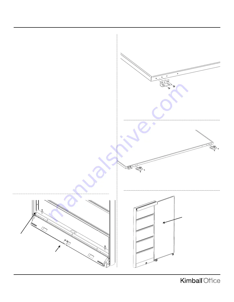
6. Starting at an angle, insert the bottom guide channel into the
panel’s bottom cross member and attach it to the frame with
two 1” flat washers and 1/4-20 x 1/2” long truss head ma-
chine screws (Figure E).
7. Install the wire way cover on the door side. It will go be-
tween the door rod guide and the panel.
8. Note: The front face of the door that has the smaller alumi-
num extrusion reveal and the back has the flat head screws.
Position the guide rod bracket on the bottom of the door. The
bracket is oriented with the face that has the vertical slots
towards the back side of the door. It is located on the same
side of the door as the top round plastic glide. Attach with
two #10 x 3/8” pan head screws (Figure F).
9. Attach the two wheel assemblies to the bottom of the door
with four #10 x 3/8” pan head screws (Figure G). The wheels
face toward the front of the door.
10. If the door has the lock option. Attach lock cam to door at
this time. See separate lock assembly instruction.
11. Insert the Privacy door into the top guide and bottom align-
ment bracket at the same time and roll the door approximate-
ly half way in to the open position (Figure H)
Installation (Continued)
Figure F
Figure G
Figure H
Figure E
Start to insert guide into
bottom panel cross member
at an angle and then rotate it
to push it all the way up.
Attach bottom guide with
two screws and washers
Roll door into top
Guide and inside
bottom alignment
bracket at the same
time.


