


PFX2512_CE
9
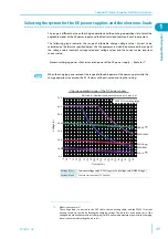
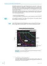
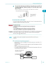
Rear panel
13 PROTECT (V) LED
It Illuminates when the status of protection function is displayed. (when it is selected by
the SELECT key)
14 ADDRESS LED
It illuminates when the LAN interface is in use and the connection method, IP address, or
channel number is displayed (when it is selected by the SELECT key).
15 SELECT key
To select the item to display on the DISPLAY.
No.
Name
Function
1
EXT CONT terminal board
External control terminal
2
SENSING connector
A connector for the sensing cables
3
S1 switch
Setting switches for the termination of TP-BUS, the addresses, and
the vibration sensor.
4
TP-BUS connectorb
A connector for maintenance
-
5
DC POWER SUPPLY connector
A connector for controlling the power supply
6
DC ELECTRONIC LOAD connector A connector for controlling the Electronic load
7
Volt / Thermometer Unit
(OP02-PFX)
An option board for expanding the number of voltage and
temperature measurement points
8
Extra slots for the option board
Slots for installing the option board
From the left: slot 1, slot 2, and slot 3
9
Input/Output terminal board
*1
*1.
The terminal cover for protecting the input/output terminal is being attached to the terminal when the PFX2512 is shipped from the
factory.
Terminals for the testing device (DUT), the DC power supply
(DCPS), and the Electronic load (DCEL)
10
Air outlet
Exhaust port for cooling
-
11
Serial number
-
-
12
Chassis terminal
A terminal used for ground the output
13
AC INPUT connector
AC inlet
14
LAN connector
A connector for communicating with BPChecker3000
No. Name
Function
See
TP
-
BUS
( PFX2121
)
DC POWER SUPPLY
NC03069-1
AC INPUT
90-250V 50-60Hz
60VA MAX
KIKUSUI ELECTRONICS CORP.
MADE IN JAPAN
EXT CONT
AWG 24
STRIP
-
GAUGE
10mm
DC PS
1
2
3
SENSING
S1
+
S
MAX60V
-
S
+
T
-
T
FG
60V
50A
6
4
35
2
11
0
8
79
+
-
+
-
+
-
DC ELECTR
ONIC LO
AD
DC EL
DUT
SH DET
RESV
8421
NC
TERMN
OFF
1
0
LA
N
RX
LINK
OP02
-
PFX
TERM
+
-
+
-
+
-
+
-
1234
THERMO
COUPLE
+
-
+
-
+
-
+
-
1
FG
234
FG
TERM
MAX20V
VO
L
T
AG
E
SENSING
5
6
8
7
9
10
11
1
14
2
3
4
13
12
Example in which a Volt / Thermometer Unit OP02-PFX is installed in slot 1 of a PFX2512.
See
Содержание PFX2515
Страница 10: ...10 PFX2512_CE This page is intentionally blank ...
Страница 11: ...General Description This chapter describes the outline of product the connectable equipments and the options ...
Страница 58: ...58 PFX2512_CE This page is intentionally blank ...
Страница 59: ...Specification This chapter contains the PFX2512 specifications and outline drawings ...
Страница 86: ...86 PFX2512_CE This page is intentionally blank ...
Страница 100: ...100 PFX2512_CE This page is intentionally blank ...
Страница 103: ......