


PFX2512_CE
53
Outline of the External Control
3
Op
e
ra
ti
o
n
s
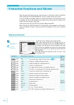
External monitoring of the operating status
The output is available for the monitoring of the operating status by the external contact. The
outputs are open collector outputs of photocouplers; they are insulated from the internal circuits of
the PFX2512.
The insulation circuit of the photocoupler of the status output consists of chassis, internal circuit,
and the insulation of 80 Vdc.
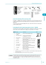
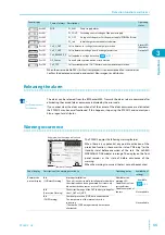
Controlling the alarm input using external contact
(
ALM IN
)
This function shuts off the outputs from the PFX2512 according to the input from an external
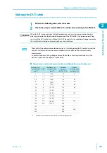
contact. Short-circuit the contact switch to apply an alarm signal input at 0.5 s or longer.
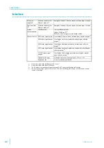
Terminal
number
Signal
Description
Circuit
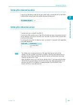
10
External alarm
common
Common for the external alarm input.
9
External alarm input
Stops the test at the LOW level.
*1
It is pulled up to +5 V at 5.1 kΩ.
*1.
This PFX2512 becomes in the state of an external alarm by short circuit with the external alarm input common,
and it stops the testing.
8
Status common
Common for the status signal.
*2
*2.
Same potential for the No.4 pin and No.8 pin of the status signal common.
7
ALM status
Becomes LOW level when the ALARM is activated.
Open collector output
6
END status
Becomes LOW level when the test is terminated.
Open collector output
5
REST status
Becomes LOW level when in the rest condition.
Open collector output
4
Status common
Common for the status signal.
3
DISCHG status
Becomes LOW level while in the discharge state.
Open collector output
2
CHG status
Becomes LOW level while in the charge state.
Open collector output
1
Unused
Do not connect any wire.
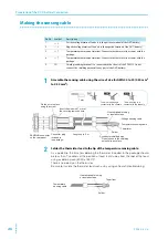
1
2
3
4 5 6 7
8
9 10
External alarm common
External alarm input
Status common
ALM status
END status
REST status
Status common
DISCHG status
CHG status
Unused
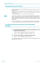
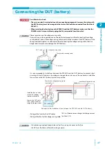
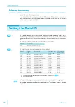
AWG 24
STRIP-GAUGE
10mm
Push this area with a
flat-blade screwdriver
while inserting the wire.
Strip coating by
10 mm and insert
the wire here.
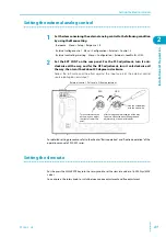
Yes
No
No
The wire is directly
incontact with the
chassis.
The wire scrap
is in contact with
the chassis.
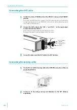
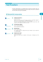
5.1 k
Ω
+5 V
9
10
8
6
5
7
2
3
1
NC
4
CAUTION
The external alarm input and the external alarm common are the potential of the internal circuit. It
should be connected with the circuit insulated from other potential such as the switch or the
photo coupler output, etc. It may cause to malfunction of the internal circuit if the wirings were
cnnected in correctly.
Содержание PFX2515
Страница 10: ...10 PFX2512_CE This page is intentionally blank ...
Страница 11: ...General Description This chapter describes the outline of product the connectable equipments and the options ...
Страница 58: ...58 PFX2512_CE This page is intentionally blank ...
Страница 59: ...Specification This chapter contains the PFX2512 specifications and outline drawings ...
Страница 86: ...86 PFX2512_CE This page is intentionally blank ...
Страница 100: ...100 PFX2512_CE This page is intentionally blank ...
Страница 103: ......