

18
Installation
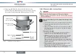
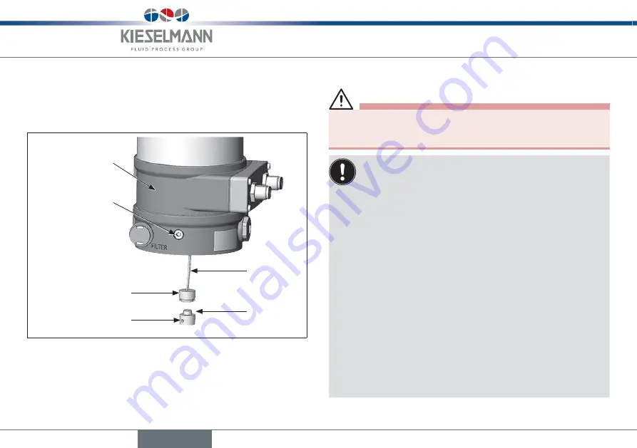
Type 8615500120-000 / 8615500130-000
→
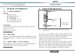
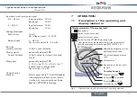
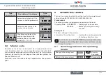
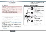
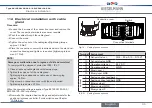
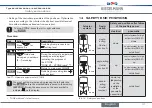
Attach type 8615500120-000 / 8615500130-000 to the
actuator using both lateral fastening screws. In doing so, tighten
the screws only lightly (maximum tightening torque: 0.5 Nm).
Electrical con-
nection housing
Fastening screws
max. 0.5 Nm
Angle of rotation
sensor
Setscrew
Sensor cable
Magnetic
encoder
Fig. 8:
Installation on rotary actuators
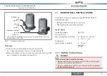
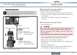
10.6 pneumatic connection
Danger!
risk of injury from high pressure in the system/device.
▶
Before working on the system or device, switch off the pressure
and vent/drain lines.
observe the following for the proper functioning of the
device:
▶
The installation must not cause back pressure to build up.
▶
To make the connection, select a hose with sufficient
cross section.
▶
Design the exhaust air line in such a way that no water or
other liquid can get into the device through the exhaust
air port (3 or 3.1).
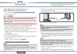
exhaust air concept:
▶
In compliance with the degree of protection IP67, an
exhaust air line must be installed in the dry area.
▶
always
maintain an applied control pressure of at least
0.5 ... 1 bar above the pressure which is required to
move the pneumatic actuator to its end position.
This ensures that the control behavior is not negatively
affected in the upper stroke range on account of too little
pressure difference.
▶
During operation, keep the fluctuations of the control
pressure as low as possible (max. ±10 %).
If fluctuations are greater, the control parameters mea-
sured with the
X.TUNE
function are not optimum.
English
Содержание 8615500120-000
Страница 93: ......
Страница 94: ...www kieselmann de...


