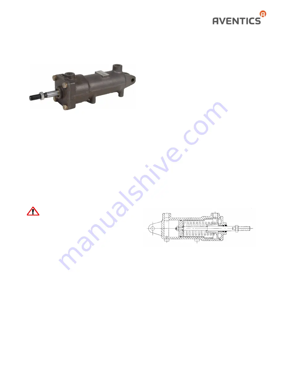
The three-position cylinder is a fixed position device when
controlled by a four-way, three-position, exhaust-centered,
control valve such as the “A” or “D”
PILOTAIR
®
VALVE.
The cylinder has a wide range of applications, being
particularly suited for shifting transmissions and positioning
hydraulic valves. It is corrosion-resistant and constructed of
lightweight, die-cast, anodized aluminum heads, pistons and
body.
Maximum stroke of the piston rod is 1” (25.4 mm) on each
side of the center position, making a total piston rod travel of
2” (50.8 mm). External envelope dimensions of the cylinder
do not change, but shorter strokes are available in
increments of 1/16” (1.59 mm) for each position. The model
number of the cylinder and the model number of the piston
stop (13A) will have an identical four-digit suffix. The first
digit denotes the stroke in inches; the last three digits show
the stroke in thousandths of an inch.
WARNING: INSTALLATION
AND MOUNTING
The user of these devices must conform to all applicable
electrical, mechanical, piping and other codes in the
installation, operation or repair of these devices.
INSTALLATION!
Do not attempt to install, operate or repair
these devices without proper training in the technique of
working on pneumatic or hydraulic systems and devices,
unless under trained supervision.
Compressed air and hydraulic systems contain high levels of
stored energy. Do not attempt to connect, disconnect or
repair these products when a system is under pressure.
Always exhaust or drain the pressure from a system before
performing any service work. Failure to do so can result in
serious personal injury.
MOUNTING!
Devices should be mounted and positioned in
such a manner that they cannot be accidentally operated.
INSTALLATION & ADJUSTMENT
Because cylinders are installed at the end of an air system,
they are vulnerable to dirt and moisture carried through the
air lines. Therefore, before installing the three-position
cylinder, all air lines in the system should be blown clean. It is
recommended that the cylinder be mounted with the ports
facing down. Gravity can then assist in preventing foreign
material from accumulating in the cylinder by removing it
through the control valve exhaust.
In providing a mounting for the cylinder, an adjustable link
must be included between the piston rod and the lever to
which the rod is connected. The cylinder stroke should be
checked in its center position when aligned with the lever to
be operated. Check for exact register, making sure the clevis
pin is free from load in the center position.
This procedure will allow any inaccuracies in leverage ratio or
manufacturing tolerance to be absorbed at the extremes of
the stroke where exact registration is of least importance.
Also, any inaccuracies will be divided between the extreme
positions. When alignment is done at one of the extreme
positions, inaccuracies are all in the same direction.
OPERATION
Maximum operating pressure of the three-position cylinder is
150 psi (10.3 bar) at a temperature range of -40°F to 180°F
(-40°C to 82°C). The cylinder is held in its center position by
a coil spring caged on the piston rod. When air pressure is
supplied to the Cap-End Port, the piston rod moves to its
extended position. When pressure is supplied to the Head-
End Port, the piston rod moves to its retracted position.
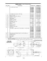
ASSEMBLY VIEW
MAINTENANCE
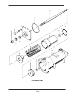
Periodically disassemble the cylinder for cleaning, inspection
and lubrication. Clean all metal parts with a nonflammable
solvent, and wash all rubber parts with soap and water.
Rinse thoroughly and blow dry with a low-pressure air jet.
Replace those parts which are damaged or worn.
Reassemble the cylinder, using the exploded and assembly
views as reference. No special tools are required. To avoid
cutting or nicking the piston “O” ring, carefully insert the
piston rod assembly into the cylinder bore with the piston
tilted at a slight angle. As the assembly proceeds, lubricate
all “O” rings with Dow Corning.
MULTIPOSITION AIR CYLINDER
CAST ALUMINUM
THREE-POSITION - SPRING-CENTERED
SERVICE INFORMATION
SM-1000.4916
Содержание R431004052
Страница 2: ...Page 2 EXPLODED VIEW ...


