Kia Carnival 2007 Скачать руководство пользователя страница 939

DTC is displayed, check the following probable cause. When the
problem is still occurring, replace the ABS control module.

b. Inoperative wheel speed sensor circuit

c. Inoperative hydraulic circuit for leakage

d. Inoperative HECU

INSPECTION PROCEDURES

DTC INSPECTION

1. Connect the Scan Tool with the data link connector and turn the ignition switch ON.

2. Verify that the system is operating to specifications.

Is the system operating to specifications?

 Check the wheel speed sensor circuit.

 Erase the DTC and recheck using Scan Tool.

CHECK THE WHEEL SPEED SENSOR CIRCUIT.

Refer to the DTC troubleshooting procedures.
Is the system operating to specifications?

 Check the stop lamp switch circuit.

 Repair or replace the wheel speed sensor.

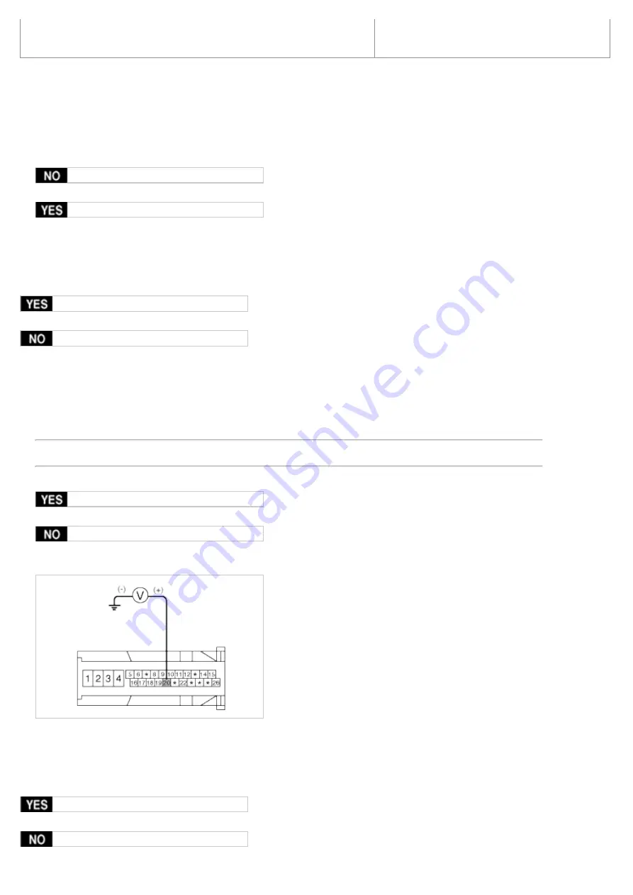
CHECK THE STOP LAMP SWITCH CIRCUIT.

1. Check that stop lamp lights up when brake pedal is depressed and turns off when brake pedal is released.

2. Measure the voltage between terminal 20 of the ABS control module harness side connector and body ground

when brake pedal is depressed.

Specification: approximately B+

Is the voltage within specification?

 Check the hydraulic circuit for leakage.

 Repair the stop lamp switch. Repair an open in the wire between the ABS control module and the stop lamp

switch.

CHECK THE HYDRAULIC CIRCUIT FOR LEAKAGE.

Refer to the hydraulic lines.
Inspect leakage of the hydraulic lines.
Is the system operating to specifications?

 The problem is still occurring, replace the ABS control module.

Содержание Carnival 2007

Страница 1: ...CHAPTER 1 General Information ...

Страница 2: ... Engine type 1 J2 9 Diesel 2 µ 2 7 3 λ3 8 Gasoline 9 Transmission type 2 Manual 5 Automatic 10 Model year 5 2005 6 2006 7 2007 11 Plant location 6 Soha plant 12 17 Production sequential number 000001 999999 ENGINE IDENTIFICATION NUMBER GASOLINE 1 Engine fuel G Gasoline 2 Engine range 4 4 cycle 4 cylinder 6 4 cycle 6 cylinder 3 Engine development order D Lambda engine 4 Engine capacity E 2656 cc µ ...

Страница 3: ...BRICANTS Parts OIL GREASE STANDARD Engine Oil Gasoline API SJ or SL SAE 5W 20 If 5W 20 engine oil is not available 5W 30 or secondary recommended engine oil for corresponding temperature range can be used Transaxle Auto DIAMOND ATF SP III SK ATF SP III Manual API Classification GL 4 SAE 75W 85 Power Steering PSF 3 Breake Steering DOT 3 or equivalent Coolant Ethlyene glycol base for aluminium radia...

Страница 4: ...oil Oil pan 4 2 4 44 3 70 Oil filter 0 3 0 32 0 26 Total 4 5 4 76 0 26 Cooling system 8 2 8 3 8 66 8 77 7 22 7 3 Manual transaxle 1 85 1 95 1 62 Automatic transaxle 10 7 11 3 9 41 Power steering 1 0 1 06 0 88 Capacities liter U S qus lmp qts SELECTION OF ENGINE OIL Gasoline 2 7 RECOMMENDED ILSAC classification GF 3 OR ABOVE RECOMMENDED API classification SL SJ OR ABOVE RECOMMENDED SAE viscosity gr...

Страница 5: ... only those lubricants which a Satisfy the requirements of the API classification b Have the proper SAE grade number for expected ambient temperature range c Lubricants that do not have both an SAE grade number and API service classification on the container should not be used ...

Страница 6: ...CHAPTER 2 Engine Mechanical System ...

Страница 7: ...thod Valve stem seal remover 09222 29000 Removal of the valve stem seal Valve stem seal installer 09222 22001 Installation of the valve stem seal Camshaft oil seal installer 09214 21000 Installation of the camshaft oil seal Valve spring compressor holder 09222 3K000 09222 3C300 Removal and installation of the intake or exhaust valves A 09222 3K000 B 09222 3C300 holder Crankshaft rear oil seal Inst...

Страница 8: ...t rear oil seal installer 09231 33000 Installation of the crankshaft rear oil seal Oil pan remover 09215 3C000 Removal of oil pan Valve guide installer 09221 3F100 A B Removal and installation of the valve guide ...

Страница 9: ...with excessive oil consumption Worn valves guides and or valve stem oil seals Repair or replace as required Worn piston rings Oil consumption may or may not cause the engine to misfire a Inspect the cylinder for a loss of compression b Repair or replace as required Engine noise on start up but only lasting a few seconds Incorrect oil viscosity a Drain the oil b Install the correct viscosity oil Wo...

Страница 10: ...onnecting rod installation a Verify the piston pins and connecting rods are installed correctly b Repair as required Engine noise under load Low oil pressure Repair or replace as required Excessive connecting rod bearing clearance Inspect the following components and repair as required a The connecting rod bearings b The connecting rods c The crankshaft Excessive crankshaft bearing clearance Inspe...

Страница 11: ...necting rod bearings a Inspect crankshaft and connecting rod bearing b Repair as required Bent or broken connecting rod a Inspect connecting rods b Repair as required Broken crankshaft a Inspect crankshaft b Repair as required ...

Страница 12: ...mpression pressure 1 176 79kPa 12 0kgf cm 170 68psi 200 250rpm Minimum pressure 1 029 69kPa 10 5kgf cm 149 34psi Difference between cylinders 98 07kPa 1 0kgf cm 14 22psi 4 If the compression pressure in 1 or more cylinders is lower than the specification above pour a small amount of engine oil into the cylinder through the spark plug hole repeat the steps 1 through 3 for the cylinder and measure t...

Страница 13: ...cket are in straight line on that of the cylinder head cover surface as shwn in the illustration It makes the piston of the No 1 cylinder position at TDC If not turn the crankshaft one revolution clockwise 6 Inspect the intake and the exhaust valve clearance 1 With the piston of the No 1 cylinder positioning at TDC the valves which can be measured its clearance are as shown below Measurement metho...

Страница 14: ... which can be measured its clearance are as shown below 7 Adjust the intake and the exhaust valve clearances 1 Set the piston of the No 1 cylinder to the TDC position 2 Remove the timing belt 3 Remove the camshaft bearing caps A B 4 Remove the camshaft assembly 5 Remove MLA Mechanical Lash Adjuster s 6 Measure the thickness of the removed tappet using a micrometer 7 Calculate the thickness of a ne...

Страница 15: ... new tappet on the cylinder head Apply engine oil on the periphery surface of the selected tappet 10 Install the intake and exhaust camshafts 11 Install the bearing caps 12 Install the timing belt 13 Turn the crankshaft two revolutions in the operating direction clockwise and realign crankshaft sprocket and camshaft sprocket timing marks A 14 Recheck the valve clearance Specification Engine coolan...

Страница 16: ...m height LH Camshaft Intake 44 5mm 1 7520in Exhaust 44 5mm 1 7520in RH Camshaft Intake 44 5mm 1 7520in Exhaust 44 5mm 1 7520in Journal outer diameter LH Camshaft Intake 27 964 27 980mm 1 1009 1 1016in Exhaust 27 964 27 980mm 1 1009 1 1016in RH Camshaft Intake 27 964 27 980mm 1 1009 1 1016in Exhaust 27 964 27 980mm 1 1009 1 1016in Bearing oil clearance Intake 0 020 0 057mm 0 0008 0 0022in Exhaust 0...

Страница 17: ... 30 000 30 025mm 1 1811 1 1821in Exhaust 30 000 30 025mm 1 1811 1 1821in MLA to tappet bore clearance Intake 0 020 0 061mm 0 0008 0 0024in 0 07mm 0 0027in or less Exhaust 0 020 0 061mm 0 0008 0 0024in 0 07mm 0 0027in or less Valve clearance Intake 0 17 0 23mm 0 0067 0 0090in 0 10 0 30mm 0 0039 0 0118in Exhaust 0 27 0 33mm 0 0106 0 0129in 0 20 0 40mm 0 0078 0 0157in Cylinder block Cylinder bore 96 ...

Страница 18: ...mm 0 0039 0 0098in 0 4mm 0 0157in Crankshaft Main journal outer diameter 61 982 62 000mm 2 4402 2 4409in Pin journal outer diameter 47 982 48 000mm 1 8891 1 8898in Main bearing oil clearance 0 004 0 022mm 0 0002 0 0009in End play 0 07 0 25mm 0 0028 0 0098in 0 30mm 0 0118in Oil pump Relief valve opening pressure 490 33 588 40kPa 5 0 6 0kgf cm 71 12 85 34 psi Engine oil Oil quantity Total 4 8 L 5 07...

Страница 19: ... bolt 8 22 15 18 6 23 5 1 9 2 4 13 7 17 4 Upper oil pan bolt 163 5mm 1 4 9 6 9 0 5 0 7 3 6 5 1 Upper oil pan bolt 154 5mm 1 4 9 6 9 0 5 0 7 3 6 5 1 Lower oil pan bolt 11 9 8 11 8 1 0 1 2 7 2 8 7 Oil drain plug 1 34 3 44 1 3 5 4 5 25 3 32 5 Engine support bracket bolt 10 94 2 58 8 68 6 6 0 7 0 43 4 50 6 Engine support bracket bolt 10 102 5 1 58 8 68 6 6 0 7 0 43 4 50 6 Camshaft bearing cap bolt 6 3...

Страница 20: ...1 9 2 4 13 7 17 4 Oil screen bolt 2 14 7 21 6 1 5 2 2 10 8 15 9 Water outlet pipe bolt 3 16 7 19 6 1 7 2 0 12 3 14 5 Water inlet pipe bolt 2 16 7 19 6 1 7 2 0 12 3 14 5 Water inlet pipe nut 1 16 7 19 6 1 7 2 0 12 3 14 5 Surge tank bolt 8 28 3 18 6 23 5 1 9 2 4 13 7 17 4 Surge tank bolt 8 80 2 18 6 23 5 1 9 2 4 13 7 17 4 Surge tank nut 2 18 6 23 5 1 9 2 4 13 7 17 4 Intake manifold bolt 4 18 6 23 5 ...

Страница 21: ...Timing system Timing belt ...

Страница 22: ...2007 2 7L V6 GASOLINE COMPONENTS ...

Страница 23: ...a tool in the auto tensioner pulley bolt and turn the bolt counter clockwise 5 Remove the timing belt upper cover A 6 Align the groove of the pulley with the timing mark of the timing belt cover by turning the crankshaft pulley clockwise Check if the timing mark of the camshaft sprocket is aligned with that of the cylinder head cover at the moment No 1 cylinder piston at TDC 7 Remove the engine mo...

Страница 24: ...ngine oil pan with a jack 1 Put a wooden or rubber block between the jack and the engine oil pan 8 Remove the crankshaft damper pulley A 9 Remove the timing belt lower cover A 10 Remove the engine support bracket A ...

Страница 25: ...little from that point B which is a matter of no importance 11 Remove the timing belt auto tensioner A 12 Remove the timing belt A Make a direction mark of revolution on the timing belt for reusal 13 Remove the tensioner arm assembly A and the idler B ...

Страница 26: ... Install the timing belt auto tensioner 1 Fixing the tensioner with a vice and compressing the rod insert a set pin a Handle the auto tensioner in the vertical position b If it is treated by laying tilting or turning over stand it vertically for about five minutes in order for air to move upward c Do not pull the pin out before its installation to the engine assembly because pulling the pin can ca...

Страница 27: ... the force 150 200N c If the rod has a stiffness press it slowly and insert the pin into the set hole d If not the tensioner is in sponge state press the rod slowly from its maximum projection to 2 9mm position the meeting point with the rod and the hole of the body two or three times Afterwards if stiffness is sensed insert the pin into the hole However if not scrap the tensioner 2 Install the au...

Страница 28: ...tion at TDC After 5minutes measure the length of the projected rod Specification 5 7mm 0 1969 0 2756in 2 Ensure the locations of the timing marks for each sprocket 8 Install the engine support bracket A Tightening torque 58 8 68 6Nm 6 0 7 0kgf m 43 4 50 6lb ft 9 Install the timing belt lower cover A Tightening torque 9 8 11 8Nm 1 0 1 2kgf m 7 8 8 7lb ft ...

Страница 29: ...ing torque 166 7 176 5Nm 17 0 18 0kgf m 123 0 130 2lb ft 11 Install the engine mounting bracket A Tightening torque 63 7 83 4Nm 6 5 8 5kgf m 47 0 61 5lb ft 12 Install the timing belt upper cover A Tightening torque 9 8 11 8Nm 1 0 1 2kgf m 7 2 8 7lb ft ...

Страница 30: ...b ft 15 Install the right side cover 16 Install the front right wheel and tire 17 Install the engine cover INSPECTION SPROCKETS TENSIONER IDLER 1 Check the camshaft sprocket and crankshaft sprocket tensioner pulley and idler pulley for abnormal wear cracks or damage Replace as necessary 2 Inspect the tensioner and the idler for easy and smooth rotation and check for play or noise Replace as necess...

Страница 31: ...ry cloth or paper Do not clean with solvent 2 When the engine is overhauled or belt tension adjusted check the belt carefully If any of the following flaws are evident replace the belt a Do not bend twist or turn the timing belt inside out b Do not allow the timing belt to come into contact with oil water and steam 3 Inspect the idler for easy and smooth rotation and check for play or noise ...

Страница 32: ...Cylinder Head Assembly ...

Страница 33: ...2007 2 7L V6 GASOLINE COMPONENTS ...

Страница 34: ......

Страница 35: ...connectors carefully while holding the connector portion a Mark all wiring and hoses to avoid misconnection b Turn the crankshaft pulley so that the No 1 piston is at top dead center 1 Remove the air duct and the battery A after disconnecting the terminals B from the battery 2 Remove the engine cover 3 Remove the intake air hose and air cleaner assembly 1 Disconnect the MAF connector A 2 Disconnec...

Страница 36: ...2 knock sensor connectors A B the oil pressure switch connector C the ignition coil harness D and the No 1 VIS Variable Induction System connector E 2 Disconnect the bank 1 front rear O2 sensor connectors A 3 Disconnect the injection connectors A B C the ground lines D the condensor connector E and the Ignition coil connectors F ...

Страница 37: ...ol Valve connectors C D and the OTS Oil Temperature Sensor connector E 5 Disconnect the MAPS Manifold Absolute Pressure Sensor connector A the ETC Electronic Throttle Control connector B and the PCSV Purge Control Solenoid Valve connector C 6 Disconnect the generator connector A and the air conditioning compressor connector B ...

Страница 38: ...or A and the ECT Engine Coolant Temperature sensor connector B 8 Disconnect the bank 2 front rear O2 sensor connectors A B and the CKP sensor connector C 9 Disconnect the bank 1 CMP sensor connector A 7 Remove the PCV Pulge Control Valve hose A ...

Страница 39: ...p Refer to ST group 12 Remove the exhaust manifold assembly Refer to Intake and exhause system 13 Remove the intake manifold assembly Refer to Intake and exhause system 14 Remove the timing belt Refer to Timing system 15 Remove the ignition coils 16 Remove the water temp control assembly 17 Remove the cylinder head cover A ...

Страница 40: ...18 Remove the camshaft bearing cap A 19 Remove the timing chain tensioner A 20 Remove the camshaft 21 Remove the bank 2 timing belt rear cover A 22 Remove the bank 1 timing belt rear cover A ...

Страница 41: ...ved as the order the deformation of the head assembly can be occurred 2 Put the cylinder head assembly on a wooden block after removal from the cylinder block Ensure that the surface between the cylinder head and the block is not damaged REPLACEMENT Valve guide 1 Using the SST 09221 3F100A remove the valve guide from the downside of the cylinder head assembly ...

Страница 42: ... After installing the valve guides insert new valves and check the clearance between the valve stems and the valve guides 5 After replacing the valve guides check if they are properly installed with the valve seats Reprocess valve seats if necessary INSTALLATION a Thoroughly clean all parts to be assembled b Always use a new head and manifold gasket c The cylinder head gasket is a metal gasket Tak...

Страница 43: ...inder head bolts apply engine oil on the thread of the bolts and the surface of the washers Tightening torque 22 6 26 5Nm 2 3 2 7kgf m 16 6 19 5lb ft 60 2 45 2 Using the SST 09221 4A000 tighten the bolts which need to be tightened with the angular tightening method 3 Install the CVVT assembly and camshaft chain sprocket with the dowel pin in the CVVT installed to the intake camshaft Ensure that th...

Страница 44: ...exagonal part of the camshaft in a vice when tightening the CVVT bolts Do not fix the CVVT housing or sprocket in a vice 4 Install the camshaft in the cylinder head assembly 1 Align the timing mark of the camshaft timinig chain LH camshaft chain timing mark RH camshaft chain timing mark Both timing marks should face upward in reassemby 5 Install the timing chain tensioner 1 Insert the set pin by p...

Страница 45: ...gf m 15 2 18 8lb ft When installing the bearing caps check the marks on them as shown below and install them in its proper position A LH RH HEAD L LH R RH B Intake Exhaust I Intake E Exhaust C Cap no 1 2 3 When installing the bearing caps turn the crankshaft to place a piston in the middle of the block because linterference between valves and pistons can occur ...

Страница 46: ...nstalling apply engine oil b The camshaft cap surface should adhere to the cylinder head assembly c Do not press an eccentric load 8 Install the CKP sensor connector bracket A 9 Install the bank 1 timing belt rear cover A 10 Install the bank 2 timing belt rear cover A ...

Страница 47: ...ylinder head cover 1 Remove oil dust or sealant on the upper surface of the cylinder before assembling cylinder head cover 2 Assemble the cylinder head cover in five minites after applying liquid gasket LOCTITE 5900 on the camshaft cap and packing part 3 Tighten the cylinder head cover bolts as following order A Tightening torque 7 8 9 8Nm 0 8 1 0kgf m 5 8 7 2lb ft ...

Страница 48: ...mbly 15 Install the intake manifold assembly 16 Install the exhaust mainfold assembly 17 Install the power steering pump Refer to ST group 18 Install the drive belt A 19 Install the heater hose 20 Connect the brake vaccume hose A 21 Install the PCV Pulge Control Valve hose A 22 Connect the engine wiring harness connectors 1 Connect the bank 1 CMP sensor connector A ...

Страница 49: ...ensor connector A and the WTS Water Temperature Sensor connector B 4 Connect the generator connector A and the air conditioning compressor connector B 5 Connect the MAPS Manifold Absolute Pressure Sensor connector A the ETC Electronic Throttle Control connector B and the PCSV Purge Control Solenoid Valve connector C ...

Страница 50: ...connector B the No 1 No 2 OCV Oil Control Valve connectors C D and the OTS Oil Temperature Sensor connector E 7 Connect the injection connectors A B C the ground lines D the condensor connector E and the Ignition coil connectors F 8 Connect the bank 1 front rear O2 sensor connectors A ...

Страница 51: ... coil harness D and the No 1 VIS Variable Induction System connector E 23 Install the fuel inlet hose A from the delivery pipe 24 Install the upper radiator hose A and lower radiator hose B 25 Install the intake air hose and air cleaner assembly 1 Install the intake air hose and air cleaner assembly C ...

Страница 52: ...y MLA Mechanical Lash Adjuster valves and valve springs as they are removed so that each item can be reinstalled in its original position 1 Remove MLA Mechanical Lash Adjuster s A 2 Remove valves 1 Using SST 09222 3K000 09222 3C300 compress the valve spring and remove retainer lock 2 Remove the spring retainer 3 Remove the valve spring 4 Remove the valve ...

Страница 53: ...ECTION CYLINDER HEAD 1 Inspect for flatness Using a precision straight edge and feeler gauge measure the surface contacting cylinder block and the manifolds for warpage Flatness of cylinder head gasket surface Standard 0 03mm 0 0012in or less Flatness of manifold gasket surface Standard 0 15mm 0 0059in or less 2 Inspect for cracks ...

Страница 54: ... outer diameter Intake 5 585 5 980mm 0 2348 0 2354in Exhaust 5 950 5 595mm 0 2343 0 2348in 3 Calculate the clearance between the valve guides and the stems by difference between the valve stem measured diameter and the valve guide measured inside diameter Valve stem to guide clearance Standard Intake 0 020 0 050mm 0 0008 0 0020in Exhaust 0 035 0 065mm 0 0014 0 0026in Limit Intake 0 10mm 0 0039in o...

Страница 55: ...er contact with the valve face If the valve seat is worn replace cylinder head 2 Before reconditioning the seat check the valve guide for wear If the valve guide is worn replace the valve guide first 3 Recondition the valve seat with a valve seat grinder or cutter The valve seat contact width should be within specifications and centered on the valve face 4 Inspect valve springs 1 Using a steel squ...

Страница 56: ...ent MLA to tappet bore clearance Standard Intake Exhaust 0 020 0 061mm 0 0008 0 0024in Limit Intake Exhaust 0 07mm 0 0027in or less CAMSHAFT 1 Inspect cam lobes Using a micrometer measure the cam lobe height Cam height Standard value Intake 44 5mm 1 7520in Exhaust 44 5mm 1 7520in If the cam lobe height is less than standard replace the camshaft 2 Check the cam lobe surface for wear or damage If ne...

Страница 57: ...8 0 0022in Exhaust 0 020 0 057mm 0 0008 0 0022in If the oil clearance is greater than the maximum replace the camshaft If necessary replace the cylinder head 7 Completely remove the plastigage 8 Remove the camshafts 4 Inspect camshaft end play 1 Install the camshafts 2 Using a dial indicator measure the end play while moving the camshaft back and forth Camshaft end play Standard value 0 05 0 15mm ...

Страница 58: ...approx 150kpa 1 5kgf cm 21psi to the port of the camshaft Perform this in order to release the lock pin for the maximum delay angle locking When the oil splashes wipe it off with a shop rag 5 After the lock pin released the CVVT assembly can turned in advanced direction If the air applied is leaked much the lock pin can not be released 6 Except the position where the lock pin meets at the maximum ...

Страница 59: ...result in oil leakage past the valve guides b Reassemble the valve stem seals 2 After applying engine oil on the outer surface of each valve stem insert the valve in the valve guide Install the valve valve spring and spring retainer When installing valve springs the side coated with enamel should face toward the valve spring retainer 3 Using the SST 09222 3K000 09222 3C300 compress the springs and...

Страница 60: ...2 Install MLAs with engine oil applied on its surface Check that the MLA rotates smoothly by hand MLA should be reinstalled in its original position 3 Install OCV Oil Control Valve A Tightening torque 7 8 9 8Nm 0 8 1 0kgf m 5 8 7 2lb ft a To install OCV with gray colored connector into RH bank b To install OCV with black colored connector into LH bank ...

Страница 61: ...n dropped b Keep clean the OCV c Do not hold the OCV sleeve during servicing d When the OCV is installed on the engine do not move the engine while holding the OCV yoke e If there is dust on the filter B of the OCV clean it all ...

Страница 62: ...Engine And Transaxle Assembly ...

Страница 63: ...a Mark all wiring and hoses to avoid misconnection 1 Remove the engine cover 2 Disconnect the neagative terminal from the battery and remove the battery A 3 Remove the intake air hose and air cleaner assembly 1 Disconnect the MAF connector A 2 Disconnect the breather hose B from air cleaner hose 3 Remove the intake air hose and air cleaner assembly C 4 Remove the battery tray A ...

Страница 64: ...engine coolant 7 Remove the upper radiator hose A and lower radiator hose B 8 Remove the transaxle oil cooler hoses A T vehicles only 9 Remove the fuel inlet hose A from the delivery pipe 10 Disconnect the engine wiring harness connectors ...

Страница 65: ...2 Disconnect the bank 1 front rear O2 sensor connectors A 3 Disconnect the injection connectors A B C the ground lines D the condenser connector E and the Ignition coil connectors F 4 Disconnect the injection harness connector A the No 2 VIS Variable Induction System connector B the No 1 No 2 OCV Oil Control Valve connectors C D and the OTS Oil Temperature Sensor connector E ...

Страница 66: ...ol Solenoid Valve connector C 6 Remove the cooling fan relay cable A 7 Disconnect the generator connector A and the air conditioning compressor connector B 8 Disconnect the bank 2 CMP sensor connector A and the WTS Water Temperature Sensor connector B 9 Disconnect the bank 2 front rear O2 sensor connectors A B and the CKP sensor connector C ...

Страница 67: ... 1 Remove the engine room fuse and relay box cover A 2 Disconnect the PCM connectors B 3 Disconnect the FAM connectors C Refer to HA group 4 Unscrew the FAM mounting bolts D 3EA and take the FAM E out of the splash shield F 5 Disconnect the connector G from the splash shield B ...

Страница 68: ...After draining or gathering power steering fluid disconnect the power steering hose A 15 Remove the radiator grille upper cover A for convenience sake 16 Disconnect the power steering return hose 17 Remove the radiator support upper member assembly A for convenience sake ...

Страница 69: ...21 Remove the front wheels and tires Refer to DS group 22 Remove the brake caliper hub nut Refer to DS group 23 Remove the tie rod end ball joint from the knuckle Refer to DS group 24 Remove the driver shaft and the stabilizer bar link Refer to SS group 25 Remove the front muffler A 26 Using a floor jack support the engine and transaxle assembly After removing the sub frame mounting bolt the engin...

Страница 70: ...insulator mounting bolt A Remove the ECM Electronic Controlled Mounting nuts and the solenoid valve connector for A T vehicles 29 Supporting the engine and transaxle assembly with a jack remove the assembly from the vehicle by loosening the sub frame mounting bolts and lifting up the vehicle slowly When removing the engine and transaxle assembly be careful not to damage any surrounding parts or bo...

Страница 71: ...ing system with the heater valve open f Clean the battery posts and cable terminals with sandpaper assemble them then apply grease to prevent corrosion g Inspect for fuel leakage After assembling the fuel line turn on the ignition switch do not operate the starter so that the fuel pump runs for approximately two seconds and fuel line pressurizes Repeat this operation two or three times then check ...

Страница 72: ...Cylinder Block 3LVWRQ DQG RQQHFWLQJ 5RG ...

Страница 73: ...2007 2 7L V6 GASOLINE COMPONENTS ...

Страница 74: ......

Страница 75: ...to HA group 8 Remove cylinder head 9 Remove A C compressor from engine Refer to EE group 10 Remove water pump assembly INSTALLATION 1 Install the water pump 2 Install the air conditioning compressor Refer to HA group 3 Install the cylinder head 4 Install the power steering pump Refer to ST group 5 Install the generator 6 Install the intake manifold 7 Install the exhaust manifold 8 Install the timi...

Страница 76: ... 2 8 7lb ft 10 Install the drive plate A Tightening torque 71 6 75 5Nm 7 3 7 7kgf m 52 8 55 7lb ft DISASSEMBLY 1 Remove the power steering pump bracket A and the knock sensor B 2 Remove the air conditioning compressor bracket A ...

Страница 77: ...3 Remove the lower oil pan A 4 Remove the oil screen A 5 Remove the upper oil pan A When removing the oil pan use the SST 09215 3C000 not to damage the contacting surface of the oil pan ...

Страница 78: ...ods and the caps together b Arrange the piston and connecting rod assemblies in the correct order 9 Remove the oil pump case 10 Remove the oil seal case A 11 Check the crankshaft end play 12 Remove the crankshaft bearing cap and check oil clearance Arrange the bearings and the bearing caps in order 13 Lift the crankshaft A out of the block being careful not to damage journals ...

Страница 79: ...k the free play between a piston and a piston pin Try to move the piston back and forth on the piston pin If any movement is felt replace the piston and the piston pin as a set 17 Remove the piston rings 1 Using a piston ring expander remove the 2 compression rings 2 Remove the 2 side rails and the oil ring by hand ...

Страница 80: ...ew connecting rod b If still out of tolerance replace the crankshaft 2 Check the connecting rod bearing oil clearance 1 Check the matchmarks on the connecting rod and cap are aligned to ensure correct reassembly 2 Remove the 2 connecting rod cap bolts 3 Remove the connecting rod cap and the lower bearing 4 Clean the crankshaft pin journal and the bearing 5 Place a plastigage across the crankshaft ...

Страница 81: ... next larger or smaller bearing the color listed above or below that one and check clearance again If the proper clearance cannot be obtained by using the appropriate larger or smaller bearings replace the crankshaft and start over If the marks are indecipherable because of an accumulation of dirt and dust do not scrub them with a wire brush or scraper Clean them only with solvent or detergent CON...

Страница 82: ... I 1 or A 47 994 48 000mm 1 8895 1 8898in II 2 or B 47 988 47 994mm 1 8893 1 8895in III 3 or C 47 982 47 988mm 1 8891 1 8893in PLACE OF IDENTIFICATION MARK CONNECTING ROD BEARING DISCRIMINATION OF CONNECTING ROD BEARING CLASS MARK THICKNESS OF BEARING A BLUE 1 5000 1 503mm 0 0591 0 0592in B BLACK 1 497 1 500mm 0 0589 0 0591in C 1 494 1 497mm 0 0588 0 0589in ...

Страница 83: ...ing a connecting rod aligner measure the bent or torsion of the rod If the measurement is near the specification adjust the rod with a press If the rod is bent or twisted excessily replace it Bending 0 05mm 100mm 0 0020in 3 9370in Torsion 0 1mm 100mm 0 0039in 3 9370in When assembling the rod without a bearing there should be no difference 4 Check the crankshaft bearing oil clearance 1 To check mai...

Страница 84: ...n If the proper clearance cannot be obtained by using the appropriate larger or smaller bearings replace the crankshaft and start over If the marks are indecipherable because of an accumulation of dirt and dust do not scrub them with a wire brush or scraper Clean them only with solvent or detergent Crankshaft bore mark location Letters have been stamped on the block as a mark for the each size of ...

Страница 85: ...018mm 2 5989 2 5991in CRANKSHAFT JOURNAL MARK LOCATION DISCRIMINATION OF CRANKSHAFT DISCRIMINATION OF CRANKSHAFT CLASS MARK OUTSIDE DIAMETER OF JOURNAL I A 61 994 62 000mm 2 4407 2 4409in II B 61 988 61 994mm 2 4405 2 4407in III C 61 982 61 988mm 2 4402 2 4405in PLACE OF IDENTIFICATION MARK CRANKSHAFT BEARING DISCRIMINATION OF CRANKSHAFT BEARING ...

Страница 86: ...ck crankshaft end play Using a dial indicator measure the thrust clearance while prying the crankshaft back and forth with a screwdriver Standard end play 0 07 0 25mm 0 0028 0 0098in Limit 0 3mm 0 0118in If the end play is greater than the maximum replace the center bearing Thrust bearing thickness 1 925 1 965mm 0 0758 0 0774in 6 Inspect the main journals and the pin journals of the crankshaft 7 U...

Страница 87: ...ler gauge measure the surface contacting the cylinder head gasket for warpage Flatness of cylinder block gasket surface Standard 0 03mm 0 0012in or less 4 Inspect cylinder bore diameter Visually check the cylinder for vertical scratchs If deep scratches are present replace the cylinder block or process the piston to be oversized 5 Inspect the cylinder bore diameter Using a cylinder bore gauge meas...

Страница 88: ...e code A on the cylinder block Class Size code Cylinder bore inner diameter A A 86 70 86 71mm 3 4134 3 4138in B B 86 71 86 72mm 3 4138 3 4142in C C 86 72 86 73mm 3 4142 3 4146in 7 Check the piston size code A on the piston top face ...

Страница 89: ...0 02 0 04mm 0 0008 0 0016in clearance 0 01mm 0 0004in for horning 4 Bore the cylinder to the calculated size Bore the cylinders in firing order to prevent the cylinders from be twisted by high temperature 5 Stop boring and start horning for the proper clearance 6 Measure the clearance between a piston and a cylinder Specification 0 02 0 04mm 0 0008 0 0016in Bore all the cylinders with the same ove...

Страница 90: ...04in No 2 0 1mm 0 004in Oil ring 0 2mm 0 008in If the clearance is greater than the maximum replace the piston 5 Inspect piston ring end gap To measure the piston ring end gap insert a piston ring into the cylinder bore Position the ring at right angles to the cylinder wall by gently pressing it down with a piston Measure the gap with a feeler gauge If the gap exceeds the service limit replace the...

Страница 91: ...diameter of the piston pin Piston pin outerdiameter 21 001 21 007mm 0 8268 0 8270in 2 Measure the piston pin to piston clearance Piston pin to piston clearance 0 007 0 022mm 0 0003 0 0009in 3 Check the difference between the piston pin outer diameter and the connecting rod small end inner diameter ...

Страница 92: ... installation 2 The piston front mark A and the connecting rod front mark must face the timing belt side of the engine 2 Install piston rings 1 Install the oil ring spacer and 2 side rails by hand 2 Using a piston ring expander install the 2 compression rings with the code mark facing upward 3 Position the piston rings so that the ring ends are as shown 3 Install the connecting rod bearings 1 Alig...

Страница 93: ... 4 Install the CKP sensor A Tightening torque 6 9 9 8Nm 0 7 1 0kgf m 5 1 7 2lb ft 5 Install main bearings Upper bearings have the oil grooves of the oil holes Lower bearings do not 1 Aligning the bearing claw with the claw groove of the cylinder block push in the 4 upper bearings A ...

Страница 94: ...gs Install the 2 thrust bearings A under the No 3 journal position of the cylinder block with the oil grooves facing outward 7 Place crankshaft A on the cylinder block 8 Place main bearing caps on cylinder block 9 Install main bearing cap bolts 1 Install and uniformly tighten the bearing cap bolts in two steps in the sequence shown Tightening torque ...

Страница 95: ...Check crankshaft end play 11 Install the piston and connecting rod assemblies a Before installing the pistons apply a coat of engine oil to the ring grooves and cylinder bores b When installing the piston ensure that the coat on the cylinder wall is not damaged or scratched 1 Install the ring compressor check that the bearing is securely in place then position the piston in the cylinder and tap it...

Страница 96: ...Maintain downward force on the ring compressor to prevent the rings from expanding before entering the cylinder bore c Use SST 09221 4A000 install connecting rod bearing cap bolts 12 Install the rear oil seal case Tightening torque 9 80 11 76Nm 1 0 1 2kgf m 7 23 8 67lb ft ...

Страница 97: ...seal case The part must be assembled within 5 minutes after sealant was applied 13 Using SST 09231 33000 install rear oil seal after applying engine oil on the rip of the oil seal 14 Install the oil pump case 15 Install upper oil pan 1 Using a gasket scraper remove all the old packing material from the gasket surfaces 2 Before assembling the oil pan the liquid sealant TB1217H should be applied on ...

Страница 98: ... Install the oil screen A Tightening torque 14 7 21 6Nm 1 5 2 2kgf m 10 8 15 9lb ft 17 Install the lower oil pan 1 Using a gasket scraper remove all the old packing material from the gasket surfaces 2 Before assembling the oil pan the liquid sealant TB1217H should be applied on lower oil pan The part must be assembled within 5 minutes after the sealant was applied a Clean the sealing face before a...

Страница 99: ... ft 18 Install the air conditioning compressor bracket A Refer to HA group 19 Install the power steering pump bracket A and the knock sensor B Tightening torque 18 6 23 5Nm 1 9 2 4kgf m 13 7 17 4lb ft a On Bank 1 the black knock sensor connector should be installed and on Bank 2 the gray one should ...

Страница 100: ...Cooling system ...

Страница 101: ...2007 2 7L V6 GASOLINE COMPONENTS ...

Страница 102: ......

Страница 103: ...avoid danger of releasing scalding engine coolant remove the cap only when the engine is cool 2 Remove drive belt A 3 Remove the timing belt 4 Remove the water pump A and gasket B WATER TEMPERATURE CONTROL ASSEMBLY 1 Drain the engine coolant 2 Remove the air cleaner assembly 3 Disconnect the radiator upper and lower hose A B ...

Страница 104: ...otector 7 Remove water temperature control assembly A and the gaskets B 8 Remove the water pipe A THERMOSTAT Removal of the thermostat would have an adverse effect causing a lowering of cooling efficiency Do not remove the thermostat even if the engine tends to overheat 1 Drain engine coolant so its level is below thermostat 2 Remove the coolant inlet pitting A and the thermostat B ...

Страница 105: ...adiator grille upper cover A 3 Remove the radiator support upper member assembly A for convenience sake The bottom side bolt A which can be seen after removing the under cover should be loosened for removal of the radiator support upper member assembly ...

Страница 106: ...4 Remove the radiator upper and the lower hoses A 5 Disconnect transaxle oil cooler hoses A Refer to TR group 6 Disconnect the radiator fan connectors A B LH RH ...

Страница 107: ...e the condenser from the radiator assembly by removing the bolts 9 Remove the radiator assembly 10 Remove the radiator cooling fan INSTALLATION WATER PUMP 1 Install the water pump A and a new gasket B with the bolts Tightening torque 14 7 21 6Nm 1 5 2 2kgf m 10 8 15 9lb ft ...

Страница 108: ...ill with engine coolant 5 Start engine and check for leaks 6 Recheck engine coolant level WATER TEMPERATURE CONTROL ASSEMBLY 1 Install the water pipe A Tightening torque 16 7 19 6Nm 1 7 2 0kgf m 12 3 14 5lb ft 2 Install the water temperature control assembly A with a new gasket B Tightening torque ...

Страница 109: ...he heater hose and ECT hose 5 Connect the ECT sensor connector 6 Connect the radiator upper and the lower hose A 7 Install the air cleaner assembly 8 Fill with engine coolant 9 Start engine and check for leaks 10 Recheck engine coolant level THERMOSTAT 1 Place thermostat B in coolant inlet pitting A Install the thermostat with the jiggle valve upward ...

Страница 110: ...s RADIATOR 1 Install the radiator fan A to the radiator Tightening torque 4 9 7 8Nm 0 5 0 8kgf m 3 6 5 8lb ft 2 Install the radiator assembly to the vehicle 3 Fix the condenser with the radiator assembly Tightening torque 4 9 7 8Nm 0 5 0 8kgf m 3 6 5 8lb ft D 6 9 9 8Nm 0 7 1 0kgf m 5 1 7 2lb ft C 4 Install the radiator bracket A B and the bleeder hose C LH RH ...

Страница 111: ...5 Connect the radiator fan connectors A B LH RH 6 Install the transaxle oil cooler hoses A Refer to TR group ...

Страница 112: ... engine coolant level INSPECTION WATER PUMP 1 Check each part for cracks damage or wear and replace the coolant pump assembly if necessary 2 Check the bearing for damage abnormal noise and sluggish rotation and replace the coolant pump assembly if necessary 3 Check for coolant leakage If coolant leaks from hole the seal is defective Replace the coolant pump assembly A small amount of weeping from ...

Страница 113: ...immediately 1 Make sure the engine and radiator are cool to the touch 2 Open the radiator cap 3 Loosen the drain plug and drain the coolant 4 Tighten the radiator drain plug securely 5 Remove drain and clean the reservoir tank 6 Fill water slowly through the radiator cap Push the upper lower hoses of the radiator so as to bleed air easily 7 Warm the engine until the cooling fan operates 2 3 times ...

Страница 114: ...eat 10 to 15 until the coolant level doesn t fall any more bleeding air out of the cooling system Check the coolant level again in the reservoir tank for 2 3 days after replacing coolant CAP TESTING 1 Remove the radiator cap wet its seal with engine coolant and install it to a pressure tester 2 Apply a pressure of 93 123kPa 0 95 1 25kgf cm 14 19psi 3 Check for a drop in pressure 4 If the pressure ...

Страница 115: ...Lubrication system ...

Страница 116: ...2007 2 7L V6 GASOLINE COMPONENTS ...

Страница 117: ... 3 Remove the front right side cover 4 Remove the front muffler 5 Remove the generator 6 Remove the timing belt 7 Remove the oil filter bracket A 8 Using SST 09215 3C000 remove the lower oil pan A Be careful not to damage the contact surfaces of upper oil pan and lower oil pan 9 Remove the oil screen A ...

Страница 118: ...ated contact with mineral oil will result in the removal of natural fats from the skin leading to dryness irritation and dermatitis In addition used engine oil contains potentially harmful contaminants which may cause skin cancer b Wear protective clothing and gloves in order to minimize the length and frequency of contact of your skin to used oil Wash your skin thoroughly with soap and water or u...

Страница 119: ...osition 5 Tighten it with the specified torque Tightening torque 16 7 24 5Nm 1 7 2 5kgf m 12 3 18 1lb ft 5 Refill with engine oil 1 Install the oil drain plug with a new gasket Tightening torque 34 3 44 1Nm 3 5 4 5kgf m 25 3 32 5lb ft 2 Fill with fresh engine oil after removing the engine oil level gauge Capacity Total 4 8 L 5 07 US qt 4 22 lmp qt Oil pan 4 2 L 4 43 US qt 3 69 lmp qt Drain and ref...

Страница 120: ...alant was applied Bead width 2 5mm 0 0984in a Make clean the sealing face before assembling two parts b Remove harmful foreign materials on the sealing face before applying sealant c When applying sealant gasket sealant must not be protrude into the inside of oil pan d To prevent leakage of oil apply sealant gasket to the inner threads of the bolt holes e After assembly wait at least 30 minutes be...

Страница 121: ... from the gasket surfaces 2 Before assembling the oil pan the liquid sealant TB1217H should be applied on the oil pan The part must be assembled within 5 minutes after the sealant was applied a Make clean the sealing face before assembling two parts b Remove harmful foreign materials on the sealing face before applying sealant c When applying sealant gasket sealant must not be protrude into the in...

Страница 122: ...3 5Nm 1 9 2 4kgf m 13 7 17 4lb ft Bolts 16 17 4 9 6 9Nm 0 5 0 7kgf m 3 6 5 1lb ft 5 Install the oil screen Tightening torque 14 7 21 6Nm 1 5 2 2kgf m 10 8 15 9lb ft Always use a new gasket 6 Install the lower oil pan 1 Using a gasket scraper remove all the old packing material from the gasket surfaces 2 Before assembling the oil pan the liquid sealant TB1217H should be applied on the oil pan The p...

Страница 123: ... the inside of oil pan d To prevent leakage of oil apply sealant gasket to the inner threads of the bolt holes e After assembly wait at least 30 minutes before filling the engine with oil 3 Fix the oil pan and tighten the bolts in several steps uniformly Tightening torque 9 8 11 8Nm 1 0 1 2kgf m 7 2 8 7lb ft 7 Install the oil filter bracket A Tightening torque 18 6 23 5Nm 1 9 2 4kgf m 13 7 17 4lb ...

Страница 124: ...oil for deterioration entry of water discoloring or thinning If the quality is visibly poor replace oil 2 Check the engine oil level After warning up the engine make the engine stand still for five minutes or more The oil level should be between the L and F marks on the dipstick then If low check for leakage and add oil up to the F mark Do not fill with engine oil above the F mark SELECTION OF ENG...

Страница 125: ... be used RELIEF SPRING 1 Check the relief plunger Apply engine oil on the plunger and check that it moves smoothly in the hole If it does not replace the plunger or the front case only in necessary cases 2 Check the relief valve spring Check deformation or damage of the relief valve spring Specification Free length 43 8mm 1 7244in Load 36 3N 3 7kg 8 21b 3 9N 0 4kg 0 9lb 40 1mm 1 5787in OIL PRESSUR...

Страница 126: ...y a fine rod A If there is continuity with pressed replace the switch 3 If there is no continuity when the pressure 49 3kpa 0 5kg cm 7 11psi is applied through the oil hole the switch is operating properly Check for air leakage If air leaks the diaphragm is broken Replace the switch ...

Страница 127: ...Intake and Exhaust system ...

Страница 128: ...2007 2 7L V6 GASOLINE COMPONENTS ...

Страница 129: ......

Страница 130: ......

Страница 131: ...e air hose and air cleaner assembly C 3 Disconnect the engine wiring harness connectors 1 Disconnect the No 1 No 2 knock sensor connectors A B the oil pressure switch connector C the ignition coil harness D and the No 1 VIS Variable Induction System connector E 2 Disconnect the bank 1 front rear O2 sensor connectors A 3 Disconnect the injection connectors A B C the ground lines D the condensor con...

Страница 132: ...ol Valve connectors C D and the OTS Oil Temperature Sensor connector E 5 Disconnect the MAPS Manifold Absolute Pressure Sensor connector A the ETC Electronic Throttle Control connector B and the PCSV Purge Control Solenoid Valve connector C 6 Disconnect the generator connector A and the air conditioning compressor connector B ...

Страница 133: ...or A and the ECT Engine Coolant Temperature sensor connector B 8 Disconnect the bank 2 front rear O2 sensor connectors A B and the CKP sensor connector C 9 Disconnect the bank 1 CMP sensor connector A 4 Remove the PCV Pulge Control Valve hose A ...

Страница 134: ...5 Remove the ETC Electric Throttle Control bracket A and the cooling hoses B 6 Disconnect the brake vaccume hose A 7 Remove the surge tank mounting bracket A 8 Remove the surge tank A ...

Страница 135: ...9 Remove the delivery pipe assembly A 10 Remove the intake manifold assembly A EXHAUST MANIFOLD ASSEMBLY 1 Remove the under cover 2 Remove the front muffler A ...

Страница 136: ...3 Disconnect the oxygen sensor connectors A 4 Remove the oil level gauge 5 Remove the heat protector A 6 Remove the exhaust manifold assembly INSTALLATION INTAKE MANIFOLD ASSEMBLY ...

Страница 137: ...Install the surge tank Tightening torque 18 6 23 5Nm 1 9 2 4kgf m 13 7 17 4lb ft 5 Install the surge tank mounting bracket Tightening torque 18 6 23 5Nm 1 9 2 4kgf m 13 7 17 4lb ft 6 Install the ETC Electronic Throttle Control system fixing bracket 7 Connect the hoses and connectors 8 Install the air cleaner assembly 9 Install the engine cover EXHAUST MANIFOLD ASSEMBLY 1 Install the exhaust manifo...

Страница 138: ...Tightening torque 39 2 58 8Nm 4 0 6 0kgf m 28 9 43 4lb ft 4 Connect the oxygen sensor connector 5 Install the under cover ...

Страница 139: ...CHAPTER 3 Engine Electrical System ...

Страница 140: ...General information ...

Страница 141: ...injury always use extreme caution and appropriate eye protection when working with batteries KEYPAD The MICRO570 button on the key pad provides the following functions BATTERY TEST PROCEDURE 1 Connect the tester to the battery a Red clamp to battery positive terminal b Black clamp to battery negative terminal Connect clamps securely If CHECK CONNECTION message is displayed on the screen reconnect ...

Страница 142: ...ication for korean manufacturer s for cranking batteries at 18 C 0 F 4 Set the CCA value displayed on the screen to the CCA value marked on the battery label by pressing up and down buttons and press ENTER The battery ratings CCA displayed on the tester must be identical to the ratings marked on battery label 5 The tester Micro570 displays battery test results including voltage and battery ratings...

Страница 143: ...ct measurement value Replace battery Replace battery and recheck the charging system Improper connection between battery and vehicle cables may cause REPLACE BATTERY retest the battery after removing cables and connecting the tester to the battery terminal directly prior to replacing the battery Bad cell replace Charge and retest the battery And then test results may cause REPLACE BATTERY replace ...

Страница 144: ...ormal System shows a normal starter draw Cranking voltage low Cranking voltage is lower than normal level Check starter Charge battery The state of battery charge is too low to test amp amp amp amp amp amp gt Charge the battery and retest Replace battery Replace battery If the vehicle is not started though the battery condition of Good and fully charged is displayed Check wiring for open circuit b...

Страница 145: ...of generator Press ENTER to test the charging system 3 The MICRO 570 will prompt you to rev the engine until the rev detected It will then collect the data 4 Press ENTER 5 The MICRO 570 will analyze the charging system output at idle for comparison to other readings ...

Страница 146: ... test at idle and prompt you to rev the engine The analyzer will determine if the charging system can provide enough current for the demands of the vehicle s electrical system When asked to turn of the accessory loads turn of the blower to high heater the high beam beadlights and rear defogger DO NOT use cyclical loads such as air conditioning or wind shield wipers 8 After the test the MICRO 570 w...

Страница 147: ...tor does not supply charging current to battery and electrical load to system fully Check belts and generator and replace as necessary High charging voltage The voltage from generator to battery is higher than normal limit during voltage regulating Check connection and ground and replace regulator as necessary amp amp amp amp amp amp amp gt Check electrolyte level in the battery Excess ripple dete...

Страница 148: ...Illustration Use Alternator pulley remover wrench 09373 27000 Removal and installation of alternator pulley REFERENCE SERVICE TOOLS Tool Number and name Illustration Use Micro 570 Battery checker a Check the battery condition b Check the charging and starting system ...

Страница 149: ...ight Wiring connection loose Tighten loose connection Electronic voltage regulator Replace voltage regulator Charging warning indicator does not go out with engine running Battery requires frequent recharging Drive belt loose or worn Adjust belt tension or replace belt Battery cable loose corroded or worn Inspect cable connection repair or replace cable Electronic voltage regulator or alternator R...

Страница 150: ...ery Battery cables loose corroded or worn out Repair or replace cables Starter motor faulty Replace Starter keeps running Starter motor Replace Ignition switch Replace Starter spins but engine will not crank Short in wiring Repair wiring Pinion gear teeth broken or starter motor Replace Ring gear teeth broken Replace fly wheel or torque converter ...

Страница 151: ...tion Alternator Type Battery voltage sensing Rate voltage 13 5 V 110A Speed in use 1 000 18 000 rpm Voltage regulator Electronic built in type Regulator setting voltage 14 2 14 8V Battery Type MF 68AH Cold cranking amperage at 18 C 0 4 F 600 A Reserve capacity 110 min Specific gravity at 20 C 68 F 1 280 0 01 a COLD CRANKING AMPERAGE is the amperage a battery can deliver for 30 seconds and maintain...

Страница 152: ...Ignition System ...

Страница 153: ...gine operating conditions are preprogrammed in the memory of the ECM Engine Control Module The engine operating conditions speed load warm up condition etc are detected by the various sensors Based on these sensor signals and the ignition timing data signals to interrupt the primary current are sent to the ECM The ignition coil is activated and timing is controlled ...

Страница 154: ...nnector A 2 Remove the ignition coil 3 Using a spark plug socket remove the spark plug Be careful that no contaminates enter through the spark plug holes 4 When replacing the spark plug always use the long reach type spark plug 1 Color Marking Tip a 2 7L Unleaded Yellow Marking Leaded Green Marking 2 Length Tip Tip PT Length a 2 7L b 83 2mm 26 5mm c Others The length is different from the specific...

Страница 155: ...g 4 Install the spark plug to the ignition coil 5 Ground the spark plug to the engine 6 Check is spark occurs while engine is being cranked To prevent fuel being injected from injectors while the engine is being cranked remove the fuel pump A relay from the fuse box Crank the engine for no more than 5 10 seconds 7 Inspect all the spark plugs 8 Using a spark plug socket install the spark plug 9 Ins...

Страница 156: ...INSPECTION OF ELECTRODES Condition Dark deposits White deposits Description a Fuel mixture too rich b Low air intake a Fuel mixture too lean b Advanced ignition timing c Insufficient plug tightening torque 2 Check the electrode gap A Standard 1 0 1 1 mm 0 0394 0 0433 in ...

Страница 157: ...INSPECT IGNITION COIL 1 Measure the primary coil resistance between terminals and Standard 0 0715 0 015Ω Mesure the resistance between the terminals No 1 and No 3 ...

Страница 158: ...Charging System ...

Страница 159: ...C current Therefore DC current appears at alternator B terminal In addition the charging voltage of this alternator is regulated by the battery voltage detection system The alternator is regulated by the battery voltage detection system The main components of the alternator are the rotor stator rectifier capacitor brushes bearings and V ribbed belt pulley The brush holder contains a built in elect...

Страница 160: ...rroded 2 Check the fuses for continuity INSPECT DRIVE BELT Visually check the belt for excessive wear frayed cords etc If any defect has been found replace the drive belt Cracks on the rib side of a belt are considered acceptable If the belt has chunks missing from the ribs it should be replaced VISUALLY CHECK ALTERNATOR WIRING AND LISTEN FOR ABNORMAL NOISES 1 Check that the wiring is in good cond...

Страница 161: ...gives an output current that is equivalent to the normal output PREPARATION 1 Prior to the test check the following items and correct as necessary Check the battery installed in the vehicle to ensure that it is good condition The battery checking method is described in the section Battery The battery that is used to test the output current should be one that has been partially discharged With a fu...

Страница 162: ...or use the lights of another vehicle to increase the electrical load The nominal output current may not be obtained if the temperature of the alternator itself or ambient temperature is too high In such a case reduce the temperature before testing again 2 Upon completion of the output current test lower the engine speed to idle and turn off the ignition switch 3 Disconnect the battery ground cable...

Страница 163: ...2 500 rpm and read the voltmeter when the alternator output current drops to 10A or less RESULT 1 If the voltmeter reading agrees with the value listed in the regulating voltage table below the voltage regulator is functioning correctly If the reading is other than the standard value the voltage regulator or the alternator is faulty REGULATING VOLTAGE TABLE Voltage regulator ambient temperature C ...

Страница 164: ...Alternator ...

Страница 165: ...2007 2 7L V6 GASOLINE COMPONENT ...

Страница 166: ...e from alternator B terminal 3 Remove the drive belt 4 Pull out the through bolt and then remove the alternator A 5 Installation is the reverse of removal DISASSEMBLY 1 Remove the alternator cover A using a screw driver B 2 Remove the slip ring guide A 3 Loosen the mounting bolts B and disconnect the brush holder assembly C 4 Remove the rectifler A with 4 screws ...

Страница 167: ...pulley A and spacer 6 Loosen the 4 through bolts A 7 Disconnect the rotor A and cover B 8 Reassembly is the reverse order of disassembly INSPECTION INSPECT ROTOR 1 Check that there is continuity between the slip rings A ...

Страница 168: ...ft C 3 If the rotor fails either continuity check replace the alternator INSPECT STATOR 1 Check that there is continuity between each pair of leads A 2 Check that there is no continuity between each lead and the coil core 3 If the coil fails either continuity check replace the alternator ...

Страница 169: ...Battery ...

Страница 170: ...enance free battery is as the name implies totally maintenance free and has no removable battery cell caps 2 Water never needs to be added to the maintenance free battery 3 The battery is completely sealed except for small vent holes in the cover ...

Страница 171: ... BATTERY DIAGNOSTIC TEST 1 CHECKING FLOW LOAD TEST 1 Perform the following steps to complete the load test procedure for maintenance free batteries 2 Connect the load tester clamps to the terminals and proceed with the test as follow ...

Страница 172: ...AGNOSTIC TEST 2 1 Make sure the ignition switch and all accessories are in the OFF position 2 Disconnect the battery cables negative first 3 Remove the battery from the vehicle Care should be taken in the event the battery case is cracked or leaking to protect your skin from the electrolyte Heavy rubber gloves not the household type should be wore when removing the battery 4 Inspect the battery tr...

Страница 173: ...minals are flush with the tops of the posts 11 Tighten the terminal nuts securely 12 Coat all connections with light mineral grease after tightening When batteries are being charged an explosive gas forms beneath the cover of each cell Do not smoke near batteries being charged or which have recently been charged Do not break live circuit at the terminals of batteries being charged A spark will occ...

Страница 174: ...Starting System ...

Страница 175: ...hen the ignition key is turned to the start position current flows and energizes the starter motor s solenoid coil The solenoid plunger and clutch shift lever are activated and the clutch pinion engages the ring gear The contacts close and the starter motor cranks In order to prevent damage caused by excessive rotation of the starter armature when the engine starts the clutch pinion gear overruns ...

Страница 176: ...t step 4 Disconnect the connector from the S terminal of solenoid Connect a jumper wire from the B terminal of solenoid to the S terminal of solenoid If the starter cranks the engine go to next step If the starter still does not crank the engine remove the starter and repair or replace as necessary 5 Check the following items in the order listed until you find the open circuit a Check the wire and...

Страница 177: ...o starter motor as follows 2 Connect a test ammeter 100 ampere scale and carbon pile rheostats shown is the illustration 3 Connect a voltmeter 15 volt scale across starter motor 4 Rotate carbon pile to the off position 5 Connect the battery cable from battery s negative post to the starter motor body 6 Adjust until battery voltage shown on the voltmeter reads 11volts 7 Confirm that the maximum amp...

Страница 178: ...Starter ...

Страница 179: ...2007 2 7L V6 GASOLINE COMPONENT ...

Страница 180: ... the connector D from the S terminal E 3 Remove the 2 bolts holding the starter then remove the starter 4 Installation is the reverse of removal 5 Connect the battery negative cable to the battery DISASSEMBLY 1 Disconnect the M terminal A on the magnet switch assembly B 2 After loosening the 3 screws A detach the magnet switch assembly B 3 Loosen the through bolts A ...

Страница 181: ...4 Remove the brush holder assembly A yoke b and armature C 5 Remove the shield A and packing B 6 Remove the lever plate A and lever packing B 7 Disconnect the planet gear A ...

Страница 182: ... socket B 10 After removing the stopper A using stopper pliers B 11 Disconnect the stop ring A overrunning clutch B internal gear C and planet shaft D 12 Reassembly is the reverse of disassembly Using a suitable pulling tool A pull the overrunning clutch stop ring B over the stopper C ...

Страница 183: ... A surface If the surface is dirty or burnt resurface with emery cloth or a lathe within the following specifications or recondition with 500 or 600 sandpaper B 5 Measure the commutator A runout a If the commutator runout is within the service limit check the commutator for carbon dust or brass chips between the segments b If the commutator run out is not within the service limit replace the armat...

Страница 184: ...Standard New 0 5 mm 0 0197 in Limit 0 2mm 0 0079 in 7 Check for continuity between the segments of the commutator If an open circuit exists between any segments replace the armature 8 Check with an ohmmeter that no continuity exists between the commutator A and armature coil core B and between the commutator and armature shaft C If continuity exists replace the armature INSPECT STARTER BRUSH Brush...

Страница 185: ...e the spring to hold it there 3 Install the armature in the housing and install the brush holder Next pry back each brush spring again and push the brush down until it seats against the commutator then release the spring against the end of the brush To seat new brushes slip a strip of 500 or 600 sandpaper with the grit side up between the commutator and each brush and smoothly rotate the armature ...

Страница 186: ...ch assembly the gear is not available separately Check the condition of the flywheel or torque converter ring gear if the starter drive gear teeth are damaged CLEANING 1 Do not immerse parts in cleaning solvent Immersing the yoke assembly and or armature will damage the insulation Wipe these parts with a cloth only 2 Do not immerse the drive unit in cleaning solvent The overrun clutch is pre lubri...

Страница 187: ...Starter Relay ...

Страница 188: ...er check that there is continuity between each terminal Terminal Continuity 30 87 NO 85 86 YES 4 Apply 12V to terminal 85 and ground to terminal 86 Check for continuity between terminals 30 and 87 5 If there is no continuity replace the starter relay 6 Install the starter relay 7 Install the fuse box cover ...

Страница 189: ...CHAPTER 4 Emission Control System ...

Страница 190: ...2007 2 7L V6 GASOLINE SCHEMATIC DIAGRAM ...

Страница 191: ...General Information ...

Страница 192: ...low rate type Evaporative Emission System a Evaporative emission canister b Purge Control Solenoid Valve PCSV HC reduction HC reduction Duty control solenoid valve Exhaust Emission System a MFI system air fuel mixture control device b Three way catalytic converter CO HC NOx reduction CO HC NOx reduction Heated oxygen sensor feedback type Monolithic type ...

Страница 193: ...2007 2 7L V6 GASOLINE COMPONENT LOCATION 1 Purge Control Solenoid Valve PCSV 2 Positive Crankcase Ventilation PCV Valve 3 Canister 4 Catalytic Converter Bank 1 ...

Страница 194: ...5 Catalytic Converter Bank 2 ...

Страница 195: ...lenoid Valve Repair or replace Rough idle or engine stalls Vacuum hose disconnected or damaged Repair or replace Malfunction of the PCV valve Replace Malfunction of the evaporative emission canister purge system Check the system if there is a problem check related components parts Excessive oil consumption Positive crankcase ventilation line clogged Check positive crankcase ventilation system ...

Страница 196: ...2 7L V6 GASOLINE SPECIFICATIONS Specification Item Specification Coil Resistance Ω 14 0 18 0 Ω 20 C 68 F TIGHTENING TORQUES Item N m kgf m lbf m Positive Crankcase Ventilation Valve 8 0 12 0 0 8 1 2 6 0 8 0 ...

Страница 197: ...Crankcase Emission Control System ...

Страница 198: ...2007 2 7L V6 GASOLINE COMPONENTS ...

Страница 199: ...e ventilation PCV valve Remove the PCV valve from the rocker cover and reconnect it to the ventilation hose 2 Run the engine at idle and put a finger on the open end of the PCV valve and make sure that intake manifold vacuum can be felt The plunger inside the PCV valve will move back and forth ...

Страница 200: ...Positive Crankcase Ventilation PVC Valve ...

Страница 201: ...ecelerating PCV valve Not operating PCV valve Fully operating Vacuum passage Restricted Vacuum passage Small Engine condition Normal operation Engine condition Accelerating and high load PCV valve Properly operating PCV valve Slightly operating Vacuum passage Large Vacuum passage Very large ...

Страница 202: ... valve and tighten to the specified torque PCV Valve installation 7 8 11 8 N m 0 8 1 2 kgf m 5 8 8 7lbf ft INSPECTION 1 Remove the PCV valve 2 Insert a thin stick A into the PCV valve B from the threaded side to check that the plunger moves 3 If the plunger does not move the PCV valve is clogged Clean it or replace ...

Страница 203: ...Evaporative Emission Control System ...

Страница 204: ...2007 2 7L V6 GASOLINE DESCRIPTION ...

Страница 205: ...ture 80 C 176 F or higher WHEN ENGINE IS COLD Engine operating condition Applied vacuum Result Idling 50 kPa 7 3 psi Vacuum is held 3 000 rpm WHEN ENGINE IS WARM Engine operating condition Applied vacuum Result Idling 50 kPa 7 3 psi Vacuum is held Within 3 minutes after engine start at 3 000 rpm Try to apply vacuum Vacuum is released After 3 minutes have passed after engine start at 3 000 rpm 50 k...

Страница 206: ...Canister ...

Страница 207: ... Disconnect the vacuum hoses A B 2 Remove the canister assembly A with unscrewing the two mounting bolts B 3 Open the canister upper cover A with unfastening the four bolts B and remove the canister C from the canister lower cover D ...

Страница 208: ... the reverse order of REMOVAL procedure INSPECTION 1 Look for loose connections sharp bends or damage to the fuel vapor lines 2 Look for distortion cracks or fuel damage 3 After removing the canister inspect for cracks damage or saturated canister ...

Страница 209: ...Purge Control Solenoid Valve PCSV ...

Страница 210: ...tion When applied Vacuum is released When discontinued Vacuum is maintained 5 Measure the resistance between the terminals of the solenoid valve PCSV coil resistance Ω 14 0 18 0Ω at 20 C 68 F INSPECTION FUNCTION AND OPERATION PRICIPLE Purge Control Solenoid Valve PCSV is installed on the surge tank and controls the passage between the canister and the intake manifold It is a solenoid valve and is ...

Страница 211: ... INSPECTION 1 Turn ignition switch OFF 2 Disconnect PCSV connector 3 Measure resistance between PCSV terminals 1 and 2 4 Check that the resistance is within the specification Specification Refer to SPECIFICATION ...

Страница 212: ...Fuel Filler cap ...

Страница 213: ...2007 2 7L V6 GASOLINE DESCRIPTION ...

Страница 214: ...Exhaust Emission Control System ...

Страница 215: ... FUEL INJECTION MFI SYSTEM This in turn allows the engine to produce exhaust gases of the proper composition to permit the use of a three way catalyst The three way catalyst is designed to convert the three pollutants 1 hydrocarbons HC 2 carbon monoxide CO and 3 oxides of nitrogen NOx into harmless substances There are two operating modes in the MFI system 1 Open Loop air fuel ratio is controlled ...

Страница 216: ...CVVT Continuously Variable Valve Timing System ...

Страница 217: ...the phase of the intake camshaft via oil pressure It changes the intake valve timing continuously OPERATION The CVVT system makes continuous intake valve timing changes based on operating conditions Intake valve timing is optimized to allow the engine to produce maximum power Cam angle is advanced to obtain the EGR effect and reduce pumping loss The intake valve is closed quickly to reduce the ent...

Страница 218: ...eplenished as much as oil leaks from the oil pump The OCV Oil flow Control Valve spool location at this time is as follows Oil pump Advance oil chamber Little by little open the inflow side to the advance oil chamber Almost close the drain side Be sure there might be a difference in the position according to the engine running state rpm oil temperature and oil pressure ...

Страница 219: ...CHAPTER 5 Fuel System ...

Страница 220: ...General Information ...

Страница 221: ...53 24100 Fuel Pressure Gauge Measuring the fuel line pressure 09353 38000 Fuel Pressure Gauge Adapter Connection between the delivery pipe and fuel feed line 09353 24000 Fuel Pressure Gauge Connector Connection between Fuel Pressure Gauge 09353 24100 and Fuel Pressure Gauge Adapter 09353 38000 ...

Страница 222: ...2007 2 7L V6 GASOLINE BASIC TROUBLESHOOTING BASIC TROUBLESHOOTING GUIDE CUSTOMER PROBLEM ANALYSIS SHEET ...

Страница 223: ...t temperature 20 C 68 F unless stated otherwise The measured resistance in except for ambient temperature 20 C 68 F is reference value Sometimes the most difficult case in troubleshooting is when a problem symptom occurs but does not occur again during testing An example would be if a problem appears only when the vehicle is cold but has not appeared when ...

Страница 224: ...oblem has disappeared with the road test SIMULATING VIBRATION a Sensors and Actuators Slightly vibrate sensors actuators or relays with finger Strong vibration may break sensors actuators or relays b Connectors and Harness Lightly shake the connector and wiring harness vertically and then horizontally SIMULATING HEAT a Heat components suspected of causing the malfunction with a hair dryer or other...

Страница 225: ...rs b When removing the connector with a lock press or pull locking lever c Listen for a click when locking connectors This sound indicates that they are securely locked d When a tester is used to check for continuity or to measure voltage always insert tester probe from wire harness side ...

Страница 226: ...ndition and locking efficiency b When the connector is disconnected Check missed terminal crimped terminal or broken core wire by slightly pulling the wire harness Visually check for rust contamination deformation and bend c Check terminal tightening condition Insert a spare male terminal into a female terminal and then check terminal tightening conditions d Pull lightly on individual wires to ens...

Страница 227: ...s is damaged secure repair or replace the harness ELECTRICAL CIRCUIT INSPECTION PROCEDURE CHECK OPEN CIRCUIT 1 Procedures for Open Circuit a Continuity Check b Voltage Check If an open circuit occurs as seen in FIG 1 it can be found by performing Step 2 Continuity Check Method or Step 3 Voltage Check Method as shown below 2 Continuity Check Method When measuring for resistance lightly shake the wi...

Страница 228: ... each connector still connected measure the voltage between the chassis ground and terminal 1 of each connectors A B and C as shown in FIG 4 The measured voltage of each connector is 5V 5V and 0V respectively So the open circuit is between connector C and B CHECK SHORT CIRCUIT 1 Test Method for Short to Ground Circuit a Continuity Check with Chassis Ground If short to ground circuit occurs as show...

Страница 229: ... and 2 in this example is below 1 Ω and higher than 1MΩ respectively Specifically the short to ground circuit is line 1 Line 2 is normal To find exact broken point check the sub line of line 1 as described in the following step b Disconnect connector B and measure the resistance between connector A and chassis ground and between B1 and chassis ground as shown in FIG 7 The measured resistance betwe...

Страница 230: ...Check the ECTS and circuit Check DTC a DTC b Low compression c Intake air leaks d Contaminated fuel e Weak ignition spark Engine stall a Test the Battery b Check the fuel pressure c Check the idle speed control circuit Check DTC d Check the ignition circuit e Check the CKPS Circuit Check DTC a DTC b Intake air leaks c Contaminated fuel d Weak ignition spark Poor driving Surge a Check the fuel pres...

Страница 231: ...ard to refuel Overflow during refueling a Test the canister close valve b Inspect the fuel filler hose pipe a Pinched kinked or blocked b Filler hose is torn c Inspect the fuel tank vapor vent hose between the EVAP canister and air filter d Check the EVAP canister a Malfunctioning gas station filling nozzle If this problem occurs at a specific gas station during refueling ...

Страница 232: ... type Driven by Electric motor SENSORS MASS AIR FLOW SENSOR MAFS Type Hot film type Specification Air Flow kg h Frequency Hz 12 6 kg h 2 617Hz 18 0 kg h 2 958Hz 23 4 kg h 3 241Hz 32 4 kg h 3 653Hz 43 2 kg h 4 024Hz 57 6 kg h 4 399Hz 72 0 kg h 4 704Hz 108 0 kg h 5 329Hz 144 0 kg h 5 897Hz 198 0 kg h 6 553Hz 270 0 kg h 7 240Hz 360 0 kg h 7 957Hz 486 0 kg h 8 738Hz 666 0 kg h 9 644Hz 900 0 kg h 10 59...

Страница 233: ...NSOR ECTS Type Thermistor type Specification Temperature Resistance kΩ C F 40 40 48 14 20 4 14 13 16 83 0 32 5 79 20 68 2 31 2 59 40 104 1 15 60 140 0 59 80 176 0 32 THROTTLE POSITION SENSOR TPS Type Variable resistor type Specification When reference voltage 5 0V Throttle Angle Output Voltage V TPS1 TPS2 0 0 5 0 10 0 5 4 5 20 0 9 4 1 30 1 4 3 6 40 1 8 3 2 50 2 3 2 7 60 2 7 2 3 70 3 2 1 8 80 3 6 1...

Страница 234: ... 4 2 6 20 C 68 F HEATED OXYGEN SENSOR HO2S Type Zirconia ZrO2 type Specification A F Ratio Output Voltage V RICH 0 80 0 92 LEAN 0 1 Item Resistance Ω Sensor Heater 3 0 4 0 21 C 69 8 F CAMSHAFT POSITION SENSOR CMPS Type Hall effect type Specification Item Specification Output Voltage V High 4 75 5 25 Low 0 0 7 Air Gap mm 0 5 1 5 CRANKSHAFT POSITION SENSOR CKPS Type Magnetic field sensitive type Spe...

Страница 235: ...pecification Item Specification Coil Resistance Ω 13 8 15 2 20 C 68 F PURGE CONTROL SOLENOID VALVE PCSV Specification Item Specification Coil Resistance Ω 14 0 18 0 20 C 68 F VARIABLE INTAKE SOLENOID VIS VALVE 1 SURGE TANK SIDE Specification Item Specification Coil Resistance Ω 29 0 35 0 22 C 71 6 F VARIABLE INTAKE SOLENOID VIS VALVE 2 INTAKE MANIFOLD SIDE Specification Item Specification Coil Res...

Страница 236: ...acket installation bolts nuts on air cleaner assembly 1 0 1 2 9 8 11 8 7 2 8 7 Camshaft position sensor Bank 1 installation bolt 0 7 1 0 6 9 9 8 5 1 7 2 Camshaft position sensor Bank 2 installation bolt 0 7 1 0 6 9 9 8 5 1 7 2 Crankshaft position sensor installation bolt 0 7 1 0 6 9 9 8 5 1 7 2 CVVT Oil control valve Bank 1 installation bolt 0 8 1 0 7 8 9 8 5 8 7 2 CVVT Oil control valve Bank 2 in...

Страница 237: ...ank 2 installation 1 9 2 4 18 6 23 5 13 7 17 4 Manifold absolute pressure sensor installation bolt 0 8 1 2 7 8 11 8 5 8 8 7 FUEL DELIVERY SYSTEM Item kgf m N m Ibf ft Fuel tank band mounting nuts 4 0 5 5 39 2 53 9 28 9 39 8 Fuel pump assembly mounting bolts 0 2 0 3 2 0 2 9 1 4 2 2 Delivery pipe installation bolts 0 9 1 4 8 8 13 7 6 5 10 1 Accelerator pedal module installation bolts 1 3 1 6 12 8 15...

Страница 238: ...Engine Control System ...

Страница 239: ...adio interference When the shielded wire is faulty the control harness must be replaced d When checking the generator for the charging state do not disconnect the battery terminal to prevent the ECM from damage due to the voltage e When charging the battery with the external charger disconnect the vehicle side battery terminals to prevent damage to the ECM Malfunction Indicator Lamp MIL Faults wit...

Страница 240: ...ition switch turned on the diagnostic trouble code DTC is recorded In this case disconnect the battery negative terminal for 15 seconds or more and the diagnosis memory will be erased THE RELATION BETWEEN DTC AND DRIVING PATTERN IN EOBD SYSTEM 1 When the same malfunction is detected and maintained during two sequential driving cycles the MIL will automatically illuminate 2 The MIL will go off auto...

Страница 241: ...iving cycles a A warm up cycle means sufficient vehicle operation such that the coolant temperature has risen by at least 40 degrees Fahrenheit from engine starting and reaches a minimum temperature of 160 degress Fahrenheit b A driving cycle consists of engine startup vehicle operation beyond the beginning of closed loop operation ...

Страница 242: ...2007 2 7L V6 GASOLINE COMPONENT LOCATION 1 PCM Powertrain Control Module 2 Mass Air Flow Sensor MAFS 3 Intake Air Temperature Sensor IATS ...

Страница 243: ...Temperature Sensor ECTS 7 Camshaft Position Sensor CMPS Bank2 6 Camshaft Position Sensor CMPS Bank 1 8 Crankshaft Position Sensor CKPS 9 Heated Oxygen Sensor HO2S Bank 1 Sensor 1 10 Heated Oxygen Sensor HO2S Bank 1 Sensor 2 11 Heated Oxygen Sensor HO2S Bank 2 Sensor 1 12 Heated Oxygen Sensor HO2S Bank 2 Sensor 2 ...

Страница 244: ...ector 26 Ignition Coil 16 Accelerator Position Sensor APS 18 CVVT Oil Control Valve OCV Bank 1 19 CVVT Oil Control Valve OCV Bank 2 20 CVVT Oil Temperature Sensor OTS 21 Purge Control Solenoid Valve PCSV 22 Variable Intake Solenoid VIS 1 Valve Surge Tank Side ...

Страница 245: ...23 Variable Intake Solenoid VIS 2 Valve Intake Manifold Side 24 Fuel Pump Relay 25 Main Relay 27 Wheel Speed Sensor WSS 28 Vehicle Speed Sensor VSS 31 A C Pressure Transducer APT ...

Страница 246: ...Engine Control Module ECM ...

Страница 247: ...2007 2 7L V6 GASOLINE CIRCUIT DIAGRAM ...

Страница 248: ......

Страница 249: ......

Страница 250: ......

Страница 251: ......

Страница 252: ...replace the PCM with a new one and then check the vehicle again If the vehicle operates normally then the problem was likely with the PCM 4 RE TEST THE ORIGINAL PCM Install the original PCM may be broken into a known good vehicle and check the vehicle If the problem occurs again replace the original PCM with a new one If problem does not occur this is intermittent problem Refer to INTERMITTENT PRO...

Страница 253: ...witch signal input Power Steering Switch 11 12 13 Clutch Switch signal input Clutch Switch 14 15 Alternator load signal input Alternator 16 Cruise Switch ground Cruise Switch 17 18 A C switch ON signal input A C Switch 19 20 21 Brake switch signal input Brake Switch 22 23 Brake lamp signal input Brake Switch 24 25 Cruise Switch signal input Cruise Switch 26 A C thermal switch signal input A C Ther...

Страница 254: ...1 Cruise SET lamp control output Cruise SET Lamp 52 Vehicle speed signal input ABS ESP Control Module With ABS ESP Euro Ⅲ Ⅳ Vehicle Speed Sensor VSS Except Euro Ⅲ Ⅳ 53 Sensor ground Intake Air Temperature Sensor IATS 54 Accelerator Position Sensor 1 signal input Accelerator Position Sensor APS 1 55 Sensor ground Accelerator Position Sensor APS 1 56 57 Sensor 5V Accelerator Position Sensor APS 2 58...

Страница 255: ...le 2 ETC Motor control output ETC Motor in ETC Module 3 4 CVVT Oil Temperature Sensor signal input CVVT Oil Temperature Sensor OTS 5 6 7 Engine Coolant Temperature Sensor signal input Engine Coolant Temperature Sensor ECTS 8 Manifold Absolute Pressure Sensor signal input Manifold Absolute Pressure Sensor MAPS 9 10 11 Reference voltage 5V Manifold Absolute Pressure Sensor MAPS 12 Battery voltage su...

Страница 256: ...inder 4 control output Ignition Coil Cylinder 4 41 Crankshaft Position Sensor Low signal input Crankshaft Position Sensor CKPS 42 43 44 45 46 47 48 Throttle Position Sensor 1 signal input Throttle Position Sensor TPS 1 49 Heated Oxygen Sensor Bank 1 Sensor 1 signal input HO2S B1 S1 Except for LEADED 50 Heated Oxygen Sensor Bank 1 Sensor 2 signal input HO2S B1 S2 Euro Ⅲ Ⅳ 51 Heated Oxygen Sensor Ba...

Страница 257: ...ntrol output Injector Cylinder 6 72 Injector Cylinder 1 control output Injector Cylinder 1 73 Heated Oxygen Sensor Bank 2 Sensor 2 Heater control output HO2S B2 S2 Euro Ⅲ Ⅳ 74 Heated Oxygen Sensor Bank 1 Sensor 2 Heater control output HO2S B1 S2 Euro Ⅲ Ⅳ 75 76 Battery Power Battery 77 Ignition Coil Cylinder 3 control output Ignition Coil Cylinder 3 78 Ignition Coil Cylinder 5 control output Igniti...

Страница 258: ... Main SW Battery Voltage 13 37V Set SW 1 3 1 7V 1 38V Resume SW 2 8 3 2V 2 82V Cancel SW 0 2 0 2V 37 54mV 26 A C thermal switch signal input A C OFF DC Max 1 0V 25mV A C ON Battery Voltage 12 57V 27 Diagnostic Data Line K Line When transmitting Pulse Hi Min Vbatt 80 11 57V Lo Max Vbatt 20 175mV When receiving Hi Min Vbatt 70 Lo Max Vbatt 30 28 29 30 31 32 A C Pressure Transducer signal input A C O...

Страница 259: ...9V 0 38V W O T 1 5 3 0V 2V 50 51 Cruise SET lamp control output Cruise OFF DC Battery Voltage 12 57V Cruise ON Max 1 0V 25mV 52 Vehicle speed signal input Vehicle Run Pulse Hi Min 5 0V 11 07V Lo Max 1 0V 125mV 53 Sensor ground Idle DC Max 50 mV 22 37mV 54 Accelerator Position Sensor 1 signal input C T Analog 0 3 0 9V 819mV W O T 4 0 4 8V 4 01V 55 Sensor ground Idle DC Max 50mV 22 6mV 56 57 Referen...

Страница 260: ...oltage 12 57V Relay ON Max 1 0V 25mV 71 Variable Intake Solenoid Valve 1 control output Active DC Max 1 0 V 175mV Inactive Battery Voltage 13 77V 72 Immobilizer lamp control output Lamp OFF DC Battery Voltage 12 77V Lamp ON Max 1 0V 25mV 73 74 75 76 77 78 Purge Control Solenoid Valve control output Inactive Pulse Hi Battery Voltage 13 83V Active Lo Max 1 0V 31 54mV 79 Wheel Speed Sensor Low signal...

Страница 261: ...ylinder 6 control output Idle Pulse 1st Voltage 200 400V 278V ON Voltage Max 2V 1 97V 20 21 Crankshaft Position Sensor High signal input Idle SINE WAVE Vp_p Min 1 0V 41 6V 22 23 Sensor Shield Idle DC Max 50 mV 21 41mV 24 Camshaft Position Sensor Bank 2 signal input Idle Pulse Hi Vcc 4 95V Lo Max 0 5V 10mV 25 Camshaft Position Sensor Bank 1 signal input Idle Pulse Hi Vcc 4 95V Lo Max 0 5V 10mV 26 2...

Страница 262: ...gnal input Racing DC Rich 0 6 1 0V Lean 0 0 4V 53 Knock Sensor KS Bank 2 High signal input Knocking Variable Frequency 0 3 0 3 V Normal 0 V 54 Knock Sensor KS Bank 2 Low signal input Knocking Variable Frequency 0 3 0 3 V Normal 0 V 55 Knock Sensor KS Bank 1 Low signal input Knocking Variable Frequency 0 3 0 3 V Normal 0 V 56 Knock Sensor KS Bank 1 High signal input Knocking Variable Frequency 0 3 ...

Страница 263: ...or Cylinder 6 control output Idle Pulse Hi Battery Voltage 13 95mV Lo Max 1 0V 55 77mV 72 Injector Cylinder 1 control output Idle Pulse Hi Battery Voltage 14 07V Lo Max 1 0V 56 7mV 73 Heated Oxygen Sensor Bank 2 Sensor 2 Heater control output Engine Run Pulse Hi Battery Voltage 13 87V Lo Max 1 0V 275mV 74 Heated Oxygen Sensor Bank 1 Sensor 2 Heater control output Engine Run Pulse Hi Battery Voltag...

Страница 264: ...Mass Air Flow Sensor MAFS ...

Страница 265: ...nt At this time heat transfer is generated by convection and this sensor loses its energy This sensor detects the mass air flow by using the energy loss and transfers the information to the PCM by frequency The PCM calculates fuel quantity and ignition timing SPECIFICATION Air Flow kg h Output Frequency Hz 12 6 kg h 2 617Hz 18 0 kg h 2 958Hz 23 4 kg h 3 241Hz 32 4 kg h 3 653Hz 43 2 kg h 4 024Hz 57...

Страница 266: ...ually a Mounting direction correct b Any contamination corrosion or damage on connector c Air cleaner s clogging or wet d MAFS cylinder s deforming or blocking by any foreign material 2 Check any leakage on intake system and intercooler system ...

Страница 267: ...Manifold Absolute Pressure Sensor MAPS ...

Страница 268: ...ir quantity and engine speed based on this signal This MAPS consists of piezo electric element and hybrid IC that amplifies the element output signal The element is silicon diaphragm type and adapts pressure sensitive variable resistor effect of semi conductor 100 vacuum and the manifold pressure applies to both sides of it respectively That is this sensor outputs the silicon variation proportiona...

Страница 269: ...COMPONENT INSPECTION 1 Connect a scantool on Diagnisis Link Connector DLC 2 Check MAPS output voltage at idle and IG ON Condition Output Voltage V Idle 0 8V 1 6V IG ON 3 9V 4 1V ...

Страница 270: ...Intake Air Temperature Sensor IATS ...

Страница 271: ...orrection of the air temperature is needed because air density varies according to the temperature So the PCM uses not only MAFS signal but also IATS signal This sensor has a Negative Temperature Coefficient NTC and its resistance is in inverse proportion to the temperature SPECIFICATION Temperature Resistance kΩ C F 40 40 100 87 20 4 28 58 0 32 9 40 10 50 5 66 20 68 3 51 40 104 1 47 60 140 0 67 8...

Страница 272: ... INSPECTION 1 Turn ignition switch OFF 2 Disconnect IATS connector 3 Measure resistance between IATS terminals 4 and 5 4 Check that the resistance is within the specification Specification Refer to SPECIFICATION ...

Страница 273: ...Engine Coolant Temperature Sensor ECTS ...

Страница 274: ...s supplied to the ECTS via a resistor in the PCM That is the resistor in the PCM and the thermistor in the ECTS are connected in series When the resistance value of the thermistor in the ECTS changes according to the engine coolant temperature the output voltage also changes During cold engine operation the PCM increases the fuel injection duration and controls the ignition timing using the inform...

Страница 275: ...isconnect ECTS connector 3 Remove the ECTS 4 After immersing the thermistor of the sensor into engine coolant measure resistance between ECTS terminals 1 and 3 5 Check that the resistance is within the specification Specification Refer to SPECIFICATION ...

Страница 276: ...Accelerator Position Sensor APS ...

Страница 277: ...ensors which adapt individual sensor power and ground line The second sensor monitors the first sensor and its output voltage is half of the first one If the ratio of the sensor 1 and 2 is out of the range approximately 1 2 the diagnostic system judges that a malfunction has occurred SPECIFICATION Pedal Position Output Voltage V Vref 5 0V APS1 APS2 C T 0 7 0 8V 0 29 0 46V W O T 3 85 4 35V 1 93 2 1...

Страница 278: ...ition Output Voltage V APS1 APS2 C T 0 70 0 80 0 29 0 46 W O T 3 85 4 35 1 93 2 18 3 Turn ignition switch OFF and disconnect the scantool from the DLC 4 Disconnect APS connector and measure resistance between APS terminals 5 6 and 4 5 APS 1 Specification Refer to SPECIFICATION 5 Disconnect APS connector and measure resistance between APS terminals 6 3 and 2 4 APS 2 ...

Страница 279: ...Specification Refer to SPECIFICATION ...

Страница 280: ...Heated Oxygen Sensor HO2S ...

Страница 281: ...ansfers the oxygen consistency of the exhaust gas to the PCM When A F ratio is rich or lean it generates approximately 1V or 0V respectively In order that this sensor normally operates the temperature of the sensor tip is higher than 370 C 698 F So it has a heater which is controlled by the PCM duty signal When the exhaust gas temperature is lower than the specified value the heater warms the sens...

Страница 282: ...Heater Resistance Ω 3 0 4 0Ω at 21 C 69 8 F WAVEFORM CIRCUIT DIAGRAM ...

Страница 283: ...COMPONENT INSPECTION 1 Check signal waveform of HO2S using a scantool Specification Refer to waveform 2 Disconnet the HO2S connector 3 Measure resistance between HO2S heater terminals 3 and 4 ...

Страница 284: ...4 Check that the resistance is within the specification Specification Refer to SPECIFICATION ...

Страница 285: ...CVVT Oil Temperature Sensor OTS ...

Страница 286: ... is a negative coefficient thermistor used by the PCM tl measure engine oil temperature for the purpose of adjusting CVVT calculations SPECIFICATION Temperature Resistance kΩ C F 40 40 52 0 20 4 16 5 0 32 6 0 20 68 2 45 40 104 1 10 60 140 0 544 80 176 0 290 100 212 0 164 120 248 0 099 CIRCUIT DIAGRAM ...

Страница 287: ...onnect OTS connector 3 Remove the OTS 4 After immersing the thermistor of the sensor into water or engine coolant measure resistance between OTS terminals 1 and 2 5 Check that the resistance is within the specification Specification Refer to SPECIFICATION ...

Страница 288: ...Knock Sensor KS ...

Страница 289: ...knocking occurs the vibration from the cylinder block is applied as pressure to the piezoelectric element At this time this sensor transfers the voltage signal higher than the specified value to the PCM and the PCM retards the ignition timing If the knocking disappears after retarding the ignition timing the PCM will advance the ignition timing This sequential control can improve engine power torq...

Страница 290: ...CIRCUIT DIAGRAM ...

Страница 291: ...Crankshaft Position Sensor CKPS ...

Страница 292: ...here is no CKPS signal input fuel is not supplied and the main relay does not operate That is vehicle can t run without CKPS signal This sensor is installed on transaxle housing and generates alternating current by magnetic flux field which is made by the sensor and the target wheel when engine runs The target wheel consists of 58 slots and 2 missing slots on 360 CA Crank Angle WAVEFORM CIRCUIT DI...

Страница 293: ...COMPONENT INSPECTION 1 Check signal waveform of CKPS and CMPS using a scantool Specification Refer to WAVE FORM ...

Страница 294: ...Camshaft Position Sensor CMPS ...

Страница 295: ...ement It is related with Crankshaft Position Sensor CKPS and detects the piston position of each cylinder which the CKPS can t detect The two CMPS are installed on engine head cover of bank 1 and 2 and uses a target wheel installed on the camshaft This sensor has a hall effect IC which output voltage changes when magnetic field is made on the IC with current flow ...

Страница 296: ...WAVEFORM CIRCUIT DIAGRAM ...

Страница 297: ...COMPONENT INSPECTION 1 Check signal waveform of CMPS and CKPS using a scantool Specification Refer to WAVE FORM ...

Страница 298: ...Injector ...

Страница 299: ...ng the control circuit the circuit voltage should be low theoretically 0V and the fuel is injected When the PCM de energizes the injector by opening control circuit the fuel injector is closed and circuit voltage should momentarily peak If an injector connector is disconnected for more than 46 seconds while the engine runs the PCM will determine that the cylinder is misfiring and cut fuel supply S...

Страница 300: ...COMPONENT INSPECTION 1 Turn ignition switch OFF 2 Disconnect injector connector 3 Measure resistance between injector terminals 1 and 2 ...

Страница 301: ...4 Check that the resistance is within the specification Specification Refer to SPECIFICATION ...

Страница 302: ...CVVT Oil Control Valve OCV ...

Страница 303: ... amount of oil flow into an assembly mounted on each intake camshaft through PCM control of an oil control valve This system uses two oil control valves one on each bank An Oil Temperature Sensor OTS is used to allow PCM monitoring of engine oil temperature As oil is directed into the chambers of the CVVT assembly the cam phase is changed to suit various performance and emissions requirements 1 Wh...

Страница 304: ...T INSPECTION 1 Turn ignition switch OFF 2 Disconnect OCV connector 3 Measure resistance between OCV terminals 1 and 2 4 Check that the resistance is within the specification Specification Refer to SPECIFICATION ...

Страница 305: ...Variable Intake Solenoid Valve VIS ...

Страница 306: ...PCM according to engine condition Refer to below table Engine Condition VIS Valve 1 Surge Tank VIS Valve 2 In manifold Operation Low Speed Closed Closed Increasing engine performance in low engine speed by reducing intake interference among cylinders Medium Speed Open Open or closed Increasing intake efficiency High Speed Open Open Minimizing intake resistance by shortening intake manifold length ...

Страница 307: ...TION 1 Turn ignition switch OFF 2 Disconnect VIS Valve connector 3 Measure resistance between VIS Valve 1 2 terminals 1 and 2 4 Check that the resistance is within the specification Specification Refer to SPECIFICATION ...

Страница 308: ...Electronic Throttle System ETS ...

Страница 309: ...cal throttle control system receives a driver s intention via a wire cable between the accelerator and the throttle valve while this ETC system uses the signal from the Accelerator Position Sensor APS installed on the accelerator pedal After the PCM receives the APS signal and calculates the throttle opening angle it activates the throttle valve by using the ETC motor Additionally it can handle cr...

Страница 310: ... Voltage V Vref 5 0V TPS1 TPS2 0 0V 5 0V 10 0 5V 4 5V 20 0 9V 4 1V 30 1 4V 3 6V 40 1 8V 3 2V 50 2 3V 2 7V 60 2 7V 2 3V 70 3 2V 1 8V 80 3 6V 1 4V 90 4 1V 0 9V 100 4 5V 0 5V 110 5 0V 0V Item Sensor Resistance TPS1 4 0 6 0kΩ at 20 C 68 F TPS2 2 7 4 1kΩ at 20 C 68 F ...

Страница 311: ...ETC MOTOR Item Sensor Resistance Coil Resistance Ω 1 275 1 725Ω at 20 C 68 F CIRCUIT DIAGRAM FAIL SAFE MODE Mode Description Symptom Possible Cause a ETC system can t proceed reliable algorithm procedure ...

Страница 312: ...ystem can t securely control engine power MODE 5 LIMIT PERFORMANCE a Engine power varies with accelerator position but driver perceives lack of engine power b MIL ON Normal vehicle running a Not reliable accelerator position signal or bad maximum power generation a Faulty APS ignition voltage or internal controller MODE 6 NORMAL Normal COMPONENT INSPECTION 1 Connect a scantool on Diagnoisis Link C...

Страница 313: ...TEM INITIALIZATION 1 Erase DTC s memorized in PCM with a scan tool 2 Turn ignition switch off and wait for about 10 seconds 3 Turn ignition switch on for more then 1 second At this time the PCM records initial position of ETC motor on its EEPROM ...

Страница 314: ...Fuel Delivery System ...

Страница 315: ...2007 2 7L V6 GASOLINE COMPONENT LOCATION ...

Страница 316: ...2007 2 7L V6 GASOLINE FUEL PRESSURE TEST ...

Страница 317: ......

Страница 318: ......

Страница 319: ...Fuel Tank ...

Страница 320: ... in this WORKSHOP MANUAL 2 Remove the striker cover A 3 Remove the Service Cover B 4 Disconnect the Fuel Pump Connector A 5 Start the engine and wait until fuel in fuel line is exhausted 6 After the engine stalls turn the ignition switch OFF 2 Lift the vehicle and support it with a jack ...

Страница 321: ...ector A and vaccum hose B 5 Remove the fuel tank band A with unscrewing the mounting bolts B and remove the fuel tank from the vehicle INSTALLATION 1 Install the Fuel Tank according to the reverse order of REMOVAL procedure Fuel tank band mounting bolts 39 2 53 9 N m 4 0 5 5 kgf m 28 9 39 8 lbf ft ...

Страница 322: ...Fuel Pump ...

Страница 323: ...SHOP MANUAL 2 Remove the striker cover A 3 Remove the Service Cover B 4 Disconnect the Fuel Pump Connector A 5 Start the engine and wait until fuel in fuel line is exhausted 6 After the engine stalls turn the ignition switch OFF 2 After disconnecting the fuel feed quick connector A and unscrewing the the eight screws B remove the fuel pump assembly ...

Страница 324: ...INSTALLATION 1 Install the Fuel Pump assembly according to the reverse order of REMOVAL procedure Fuel Pump assembly mounting bolts 2 0 2 9 N m 0 2 0 3 kgf m 1 4 2 2 lbf ft ...

Страница 325: ...CHAPTER 6 Automatic Transaxle System ...

Страница 326: ...General Information ...

Страница 327: ...2007 2 7L V6 GASOLINE SPECIAL TOOLS TOOL Number and name Illustration Use 09200 38001 Engine support fixture Removal and installation of transaxle ...

Страница 328: ... 0 8 1 2 5 8 8 6 Input shaft speed sensor 10 12 1 0 1 2 7 8 Output shaft speed sensor 10 12 1 0 1 2 7 8 Manual control lever 18 25 1 8 2 5 13 18 Transaxle range switch 10 12 1 0 1 2 7 8 Valve body cover 10 12 1 0 1 2 7 8 Valve body mounting bolt 10 12 1 0 1 2 7 8 Oil temperature sensor 10 12 1 0 1 2 7 8 Oil filler plug 29 34 2 9 3 4 21 4 25 1 Oil drain plug 40 50 4 0 5 0 29 36 Solenoid valve suppo...

Страница 329: ...ATF SP III 8 5ℓ 9 0 Us qt 7 5Imp qt SEALANT Item Specified Sealant Rear cover Torque converter housing Valve body cover Three Bond TB 1281B or LOCTITE FMD 546 Transmission case side cover Three Bond TB 1389 or LOCTITE 518 Side cover Three Bond TB 1389 or LOCTITE 518 587 ...

Страница 330: ...Automatic Transaxle System ...

Страница 331: ...ch of the clutches and brakes and is independently controlled Feedback control and correction control is performed in all gears as well as utilization of mutual control system to increase shift feeling The torque converter damper clutch uses a partial lock up and full lock up system An additional control method called the HIVEC system neural network is adopted to increase shift feeling Block Diagr...

Страница 332: ...d at T F driven gear 4A T Crank angle sensor Detect engine speed TPS Gasoline Throttle opening ratio by potentiometer Air conditioner switch A C load by thermister Inhibitor switch Select lever position by contact switch Brake switch Brake pedal position Vehicle speed sensor Detect vehicle speed by speedometer driven gear Sport mode switch Sport mode On Off signal ...

Страница 333: ...out 0 1sec during up shift 0 2sec during downshift As the selector lever is pushed upward or downward one time the gear is up shifted or downshifted by one gear Signals of sports mode switch Items Mode S W UP S W DOWN S W D range selection OFF OFF OFF Sports mode selection ON OFF OFF Sports mode up shift selection ON ON OFF Sports mode downshift selection ON OFF ON Controller Area Network CAN Prev...

Страница 334: ..._BAT Max 1 0V 12 9V 0V A04 R Range Selection R Position Otherwise DC Voltage V_BAT Max 1 0V 12 3V 0V A05 N Range Selection N Position Otherwise DC Voltage V_BAT Max 1 0V 13 2V 0V A06 D Range Selection D Position Otherwise DC Voltage V_BAT Max 1 0V 13 2V 0V A07 Select Position DC Voltage V_BAT Max 1 0V 13 2V 0V A08 Up Position DC Voltage V_BAT Max 1 0V 13 2V 0V A09 Down Position DC Voltage V_BAT Ma...

Страница 335: ...ence 12 5 2 27 5 2 42 5 2 57 5 2 72 5 2 N A Sports mode B03 UD Solenoid Shifting Pulse HI V_BAT LO Max 1 0V Vpeak Max 70V 14 4V 0 35V 56 3V W H Open DTC Spec P0755 DTC P0755 B05 N A B06 Oil temperature sensor_ATM Idle Analog 0 5V 4 5V 4 4V 3 1V 16Hz B09 Output speed sensor 30kph Pulse HI Min 4 0V LO Max 1 0V 5 08V 0 34V W H Open DTC Spec P0722 DTC P0722 B10 Input speed sensor Idle Pulse HI Min 4 0...

Страница 336: ...15 4V 0 45V 56 3V W H Open DTC Spec P0770 DTC P0770 B45 2ND Solenoid Shifting Pulse HI V_BAT LO Max 1 0V Vpeak Max 70V 15 4V 0 45V 56 3V W H Open DTC Spec P0760 DTC P0760 B46 N A B47 N A B59 Variable Solenoid Idle Pulse HI V_BAT LO Max 1 0V Vpeak Max 70V 1 8 1 2V N range 0 03V DC D range 600Hz W H Open DTC Spec P0748 DTC P0748 B65 N A B66 N A B75 Variable Solenoid Idle Pulse HI V_BAT LO Max 1 0V V...

Страница 337: ...ccurs in its electric control the switch valve and fail safe valve is able to move to enable 3rd speed drive or reverse d The hydraulic system consists of oil pump regulator valve solenoid valves pressure control valve and valve body e In order to control the optimal line pressure and inprove the efficiency of power transmission according to maximize the efficiency of the oil pump VFS Variable For...

Страница 338: ...ce and the magnetic force the spring force is mechanical characteristics decided at the stage of design and the magnetic force is controlled by TCM This electrical magnetic force is proportional to the current So TCM will control the current In case of VFS valve the electrical time constant is considered to decide the frequency for the current not to be fluctuated even though turns on or off the i...

Страница 339: ...ucing valve length can be adjusted by rotating the screw on the picture As you rotate the screw toward clockwise by 90 the reducing pressure will increase about 1 0bar However the reducing pressure is used just as a supply pressure for the solenoid valves except Low Reverse Reduction and Damper Clutch control solen so this may not be handled to rotate in the field service shop VFS is operated base...

Страница 340: ...Reverse Reduction solenoid because the variable line pressure is not available at reverse range HYDRULIC PRESSURE TABLE Under the constant current amount of VFS 200mA the line pressure will become as below table Be sure that the following data can be achieved by specific special facility or device to check the performance of A T assembly not on the vehicle however we can refer the maximum pressure...

Страница 341: ...75 210 40 30 6 100 0 100 100 0 0 0 UD 1030 20 149 3 60 470 40 68 6 75 170 40 25 6 100 0 100 0 100 0 100 DIR 0 75 270 40 39 6 60 540 40 78 6 0 1030 20 149 3 Measuring condition a PG A Input speed 2 500rpm b Manual valve position D c DCC Solenoid duty 0 N P ...

Страница 342: ...D 1ST gear ...

Страница 343: ...D 2ND gear ...

Страница 344: ...D 3nd gear ...

Страница 345: ...D 4th gear ...

Страница 346: ...Reverse ...

Страница 347: ......

Страница 348: ...g Position of Valve Body Variable shift pattern Communication protocol and method Step gate type shift lever Item Details Weight Reduction 1 Aluminum oil pump a 2 3kg Approx 2 Pressed parts a Retainer and hub of brakes and clutches b Carrier of planetary gear set Better shift quality 1 Independent control of clutches and brakes enabled better control of hydraulic pressure and skiped shifts 4 to 2 ...

Страница 349: ...Dynamic drive by sports mode ...

Страница 350: ...S AND FUNCTION Operating Element Symbol Function Under drive clutch UD Connect input shaft and under drive sun gear Reverse clutch REV Connect input shaft and reverse sun gear Overdrive clutch OD Connect input shaft and over drive carrier ...

Страница 351: ... and the output shaft Both shafts are in line with the engine crankshaft The input shaft includes the overdrive clutch reverse clutch underdrive clutch one way clutch 2ND brake low reverse brake overdrive planetary carrier output planetary carrier and transfer drive gear The output shaft includes the transfer driven gear CLUTCHES The gear changing mechanism utilizes three multi disc clutches The r...

Страница 352: ...ance fluid chamber A the space between the piston and return spring retainer B is also subjected to centrifugal force Thus the hydraulic pressure on one side of the piston cancels out the hydraulic pressure on the other side and the piston does not move REVERSE CLUTCH AND OVERDRIVE CLUTCH The reverse clutch C operates when the reverse gear is selected and transmits driving force from the input sha...

Страница 353: ...second brake are as illustrated below As shown the discs and plates of the two brakes are arranged on either side of the rear cushion plate E which is itself secured to the case F by a snap ring OWC To improve the shift feeling from 1st to 2nd gear OWC was adopted on the low reverse brake annulus gear Instead of hydraulic fixing by Low reverse brake at the 1st gear this mechanical fixing device wa...

Страница 354: ...ng that supports the drive gear is a preloaded type that eliminates rattle and the rigidity of the gear mounting has been increased by bolting the bearing directly onto the case OUTPUT SHAFT TRANSFER DRIVEN GEAR As shown in the illustration below the transfer driven gear is press fitted onto the output shaft and the output shaft is secured by a locking nut and supported by bearings The locking nut...

Страница 355: ... up the parking sprag As a result the parking sprag meshes with the transfer driven gear parking gear thereby locking the output shaft To minimize the operating force required a roller is fitted to the end of the rod POWER TRAIN P POSITION Hydraulic pressure is applied to the LR brake and the RED brake so power is not transmitted from the input shaft to the UD clutch or OD clutch and the output sh...

Страница 356: ... differential gear through the differential drive gear 2nd GEAR POWER FLOW Hydraulic pressure is applied to the UD clutch A the 2nd brake B and the one way clutch OWC then the UD clutch transmits driving force from the input shaft to the UD sun gear and the 2nd brake locks the reverse sun gear to the case The UD sun gear of the planetary gear drives the output pinion gear and the LR annulus gear a...

Страница 357: ...ear and the output carrier and the output carrier drives the transfer drive gear and the transfer drive gear drives the transfer driven gear of the output shaft and power is transmitted to the differential gear through the differential drive gear 4th GEAR POWER FLOW Hydraulic pressure is applied to the OD clutch A and the 2nd brake B then the OD clutch transmits driving force from the input shaft ...

Страница 358: ... locks the LR annulus gear and OD planetary carrier to the case The reverse clutch drives the reverse sun gear and the reverse sun gear drives the output carrier through the OD pinion gear and the output carrier drives the transfer drive gear and the transfer drive gear drives the transfer driven gear of the output shaft and power is transmitted to the differential gear through the differential dr...

Страница 359: ... Trouble symptom Probable cause Communication with HI SCAN is not possible If communication with the HI SCAN is not possible the cause is probably a defective diagnosis line or the TCM PCM is not functioning a Malfunction diagnosis line b Malfunction of connector c Malfunction of the TCM PCM ...

Страница 360: ... train c Malfunction of the oil pump d Malfunction of the valve body Malfunction when starting Engine stalling when shifting If the engine stalls when the selector lever is shifted from N to D or R range while the engine is idling the cause is probably a malfunction of the engine system damper clutch solenoid valve valve body or torque converter damper clutch malfunction a Malfunction of the engin...

Страница 361: ...r it is related to control and is not an abnormality a Malfunction of the valve body Does not shift No diagnosis codes If shifting does not occur while driving and no diagnosis codes are output the cause is probably a malfunction of the transaxle range switch or TCM PCM a Malfunction of the transaxle range b Malfunction of the TCM PCM Malfunction while driving Poor acceleration If acceleration is ...

Страница 362: ...GEAR 2 INCORRECT RATIO ON 10 P0733 GEAR 3 INCORRECT RATIO ON 11 P0734 GEAR 4 INCORRECT RATIO ON 12 P0741 TORQUE CONVERTER CLUTCH STUCK OFF ON 13 P0742 TORQUE CONVERTER CLUTCH STUCK ON ON 14 P0743 TORQUE CONVERTER CLUTCH CONTROL SOLENOID VALVE OPEN or SHORT GND ON 15 P0748 VFS SOLENOID OFF 16 P0750 LOW and REVERSE SOLENOID VALVE CIRCUIT OPEN or SHORT GND ON 17 P0755 UNDER DRIVE SOLENOID VALVE CIRCU...

Страница 363: ...ol till IG Off Failsafe according to the DTC a Refer the detail description in the previous page for the indicated number on the Failsafe column Items Type of error Failsafe OBD II relevant DTC DTC Oil temperature sensor Short to ground 2 3 7 8 11 P0712 P0712 Open or short to B P0713 P0713 Stuck signal P0711 P0711 Sensor fail P0711 P0711 PG A Short to ground 1 11 P0717 P0717 Open or short to B PG ...

Страница 364: ...000rpm 7 9 TPS sensor Sensor error TPS 50 SERVICE DATA LIST WITH SCAN TOOL No ITEM NAME UNIT DATA Data Description Failure 1 ENGINE RPM rpm 700 rpm Current Engine rpm 0 rpm 2 VEHICLE SPEED km h 0km h Current Vehicle speed 0km h 3 THROTTLE P SENSOR 12 5 Current TPS open angle 0 4 INPUT SPEED PG A rpm 700 rpm Input speed rpm Always output rpm when turning start ON 0 rpm 5 OUTPUT SPEED PG B rpm 0 rpm...

Страница 365: ...DE A B C D E F G H I J K F A B C D is control mode F is release mode F HIVEC SAT SIEMENS ADAPTIVE TRANSMISSION CONTROL Mode Shift Patten Shift patten Description Help SCAN DISPLAY ECONOMY Economy Driver shift patten for flat road A MEDIUM Shift patten for medium road B SPORTS Shift patten for sport road C LOAD 1 Shift patten for low land slow grade and slope D LOAD 2 Shift patten for low land stee...

Страница 366: ... b Engine Stopped Starting test with lever P or N range Starting should be possible Starting possible or impossible 4 Warming up Drive for 15 minutes or more so that the automatic fluid temperature becomes 70 90 C Gradually rises to 70 90 C Oil temperature sensor 5 a Engine Idling b Selector lever position N A C switch 1 ON 2 OFF 1 ON 2 OFF Triple pressure switch Accelerator pedal 1 Released 2 Hal...

Страница 367: ...he shifting operation is made Malfunction when shifting Displaced shift points Does not shift Does not shift from 1 to 2 or 2 to 1 Does not shift from 2 to 3 or 3 to 2 Does not shift from 3 to 4 or 4 to 3 8 Selector lever position N Carry out on a flat and straight road Move selector lever to R range drive at constant speed of 10km h The ratio between input and output shaft speed sensor data shoul...

Страница 368: ...re b Low reverse brake B slippage 2 Stall speed is to high in D range only a Underdrive clutch C slippage 3 Stall speed is too high in R range only a Reverse clutch A slippage 4 Stall speed too low in both D and R ranges a Malfunction of torque converter D b Insufficient engine output HYDRAULIC PRESSURE TEST 1 Warm up the engine until the automatic transaxle fluid temperature is 80 100 C 2 Lift up...

Страница 369: ... pressure Reverse clutch pressure Overdrive clutch pressure Low reverse brake pressure Second brake pressure Damper clutch Apply pressure DA Damper clutch Release pressure DR P 2 500 260 340 38 50 R Reverse 2 500 1 270 1 770 185 256 1 270 1 770 185 256 N 2 500 260 340 38 50 1st gear 2 500 430 510 62 74 1 010 1 050 146 152 2nd gear 2 500 430 510 62 74 430 510 62 74 ...

Страница 370: ...ore than 730 100 0 10 0 1 4th gear 2 500 430 510 62 74 780 880 110 130 More than 730 100 0 10 0 1 The values are subject to change according to vehicle model or condition Depress the acceleration pedal GENTLY under no load when measuring the hydraulic pressure ...

Страница 371: ...5 lmp qt Low fluid level can cause a variety of a abnormal conditions because it allows the pump to take in air along with fluid Air trapped in the hydraulic system forms bubbles which are compressable Therefore pressures will be erratic causing delayed shifting slipping clutches and brakes etc Improper filling can also raise fluid level too high When the transaxle has too much fluid gears churn u...

Страница 372: ...E 40 50Nm 4 0 5 0 kgf m 29 36 lb ft 5 Pour the new fluid in through the oil filler tube Stop pouring if the full volume of fluid cannot be poured in 6 Repeat the procedure in step 2 Check the old fluid for contamination If it has been contaminated repeat the steps 5 and 6 7 Pour the new fluid in through the oil filler tube 8 Reconnect the hose which was disconnected in step 1 above and firmly repl...

Страница 373: ......

Страница 374: ...Automatic Transaxle ...

Страница 375: ...2007 2 7L V6 GASOLINE COMPONENTS 1 ...

Страница 376: ...COMPONENTS 2 ...

Страница 377: ...COMPONENTS 3 ...

Страница 378: ...COMPONENTS 4 ...

Страница 379: ......

Страница 380: ...ses for identification not to be confused 1 Remove the battery A 2 After disconnecting the AFS connector A and removing the alr cleaner upper body B taka the air cleaner filter out of the air cleaner under body 3 Remove the air cleaner assembly B by removing the two mounting bolts A 4 Remove the battery tray B by removing the four mounting bolts A ...

Страница 381: ...5 Remove the inhibiter switch connector A 6 Remove the solenoid valve connector A 7 Remove the input speed sensor connector A 8 Remove the output speed sensor connector A ...

Страница 382: ...peed sensor connector A 10 Remove the control cable assembly C by removing the nut A and clip B 11 Disconnect the transaxle oil cooler hoses B from the tubes by loosening the clamps A 12 Remove the transaxle mounting bolts A ...

Страница 383: ...14 Using the SST 09200 38001 hold the engine and transaxle assembly safely 15 Remove the transaxle insulator mounting B bolts A 16 Remove the front wheels see SS group 17 Lift up the vehicle 18 Remove the power steering column joint bolt and the VRS connector A see ST group ...

Страница 384: ...e lower arm the tie rod end ball joint the stabilizer bar link from the front knuckle see SS group 24 Remove the roll stopper mounting bolts 25 Remove the mounting bolts from the sub frame by supporting the sub frame with a jack see SS group 26 Remove drive shaft from transaxle see DS group 27 Install a jack for supporting the transaxle assembly 28 Remove the drive plate bolts A and the transaxle ...

Страница 385: ...and apply grease to prevent corrosion 1 Lowering the vehicle or lifting up a jack install the transaxle assembly 2 Tighten the transaxle lower mounting bolts B 4EA TORQUE 65 85 Nm 6 5 8 5 kgf m 47 0 61 5 lb ft 3 Install the drive plate bolts A by turning the timing gear TORQUE 46 53 Nm 4 6 5 3 kgf m 33 3 38 3 lb ft 4 After removing a jack insert the drive shafts see DS group 5 Install the sub fram...

Страница 386: ...ing column joint bolt and the VRS connector A see ST group 10 Connect the return tube A with a clamp see ST group 11 Install the front wheels and tires 12 Tighten the transaxle insulator mounting B bolt A TORQUE 90 110 Nm 9 11 kgf m 65 1 79 5 lb ft ...

Страница 387: ... 8 5 kgf m 47 0 61 5 lb ft 14 Remove the SST 09200 38001 holding the engine and transaxle assembly 15 Install the starter motor see EE group TORQUE 65 85 Nm 6 5 8 5 kgf m 47 0 61 5 lb ft 16 Connect the power steering pressure tube A to the power steering oil pump ...

Страница 388: ...xle oil cooler hoses A to the tubes by fastening the clamps B 18 Install the control cable assembly C by tightening the nut A and clip B TORQUE 8 12 Nm 0 8 1 2 kgf m 5 8 8 6 lb ft 19 Install the inhibiter switch connector A ...

Страница 389: ...valve connector A 21 Install the input speed sensor connector A 22 Install the output speed sensor connector A 23 Install the vehicle speed sensor connector A 24 Install the battery tray B by removing the four mounting bolts A ...

Страница 390: ...ting bolts A 26 Reassemble the air cleaner filter install the air cleaner upper body B and connect the air flow sensor connector A 27 Install the battery A 28 Refill the transaxle fluid see Service adjustment procedure 29 Refill the power steering fluid see ST group ...

Страница 391: ...ect the Hi Scan Pro connector to the data link connector under the crash pad and power cable to the cigar jack under the center facia b Turn the ignition switch on and power on the Hi Scan Pro c Select the vehicle s name d Select AUTOMATIC TRANSAXLE e Select RESETTING AUTO T A VALUES and perform the procedure f Perform the procedure by pressing F1 REST ...

Страница 392: ...Valve Body System ...

Страница 393: ...Solenoid Valve ...

Страница 394: ...0 0 5 Ω LR 2ND UD OD TCC 4 35 0 5 Ω VFS Surge voltage 56 V Except VFS LR 2ND UD OD DCC Location Solenoid Valves Schedule Position Solenoid valves Operation LR 2ND UD OD DCC 1st gear OFF ON OFF ON OFF 2nd gear ON OFF OFF ON OFF 3rd gear ON ON OFF OFF ON 4th gear ON OFF ON OFF ON Reverse OFF ON ON ON OFF N P STD mode OFF ON ON ON OFF N P Hold mode ON OFF ON ON OFF Reference value DCC solenoid valve ...

Страница 395: ...low remove the valve body cover 2 Measure the resistance again after disconnecting solenoid valve connector Specification 20 C 2 5 3 5 Ω LR 2ND UD OD TCC 3 If the value is out of specification replace the solenoid valve Pin No Name Resistance 6 9 DCC TCC 2 5 3 5Ω 20 C 6 11 LR 4 5 2ND 3 5 UD 5 12 OD ...

Страница 396: ......

Страница 397: ...VFS Variable Force Solenoid Valve ...

Страница 398: ...ternal resistance 3 0 0 5 Ω LR 2ND UD OD TCC 4 35 0 5 Ω VFS Surge voltage 56 V Except VFS VFS Location VFS Control pressure Input Current mA Control Pressure No line pressure Increasing Current Decreasing Current MAX Kgf cm Kpa MIN Kgf cm Kpa Δ Kgf cm Kpa MIN Kgf cm Kpa 100 6 52 639 5 87 575 64 200 6 23 611 5 70 559 52 5 43 532 300 5 76 564 5 24 514 50 4 49 484 400 5 08 498 4 59 450 48 4 30 421 50...

Страница 399: ... 0 24 24 0 0 24 Test condition Ps Supply Pressure Ps 7 1 0 3 KGf cm Pc Control Pressure Pex Exhaust Pressure Atmosphere pressure ATF DIAMOND ATF SP Ⅲ ATF temperature 30 3 C 86 F Coil resistance 4 35 35Ω Dither Frequency 600 20Hz In case of VFS solenoid valve the relation between Duty and oil pressure can t be expressed ...

Страница 400: ...ccording to the chart below remove the valve body cover 2 Measure the resistance again after disconnecting solenoid valve connector Specification 20 C 4 3 4 4Ω VFS 3 If the value is out of specification replace the solenoid valve Pin No Name Resistance 7 8 VFS 4 3 4 4Ω 20 C ...

Страница 401: ...Automatic Transaxle ControlSystem ...

Страница 402: ...Input Speed Sensor ...

Страница 403: ...ion 22mA MAX Sensor body and sensor connector have been unified as one Hall type sensor specification Air gap mm Input shaft speed sensor 1 3 Coil Resistance Input shaft speed sensor over 1MΩ Peak Peak Voltage High 4 8 5 2V Low 0 8V Wave Form With High scan Hall Type Sensor Structure Interface ...

Страница 404: ......

Страница 405: ...t B 3 Inspect the input shaft speed sensor bore 5 Apply a light coat of automatic transaxle fluid to the O ring seal before installation 6 Install the input shaft speed sensor 7 Install the control cable mounting bracket 8 Connect the input shaft speed sensor connector 9 Install the holder of the control cable 10 Adjust the control cable to transaxle range switch and tighten the transaxle manual l...

Страница 406: ...Output Speed Sensor ...

Страница 407: ...on 22mA MAX Sensor body and sensor connector have been unified as one Hall type sensor specification Air gap mm Output shaft speed sensor 0 85 Coil Resistance Output shaft speed sensor over 1MΩ Peak Peak Voltage High 4 8 5 2V Low 0 8V Wave Form With High scan Hall Type Sensor Structure Interface ...

Страница 408: ......

Страница 409: ...eplacement 2 Remove the output shaft speed sensor A 1 Disconnect the output shaft speed sensor connector B 2 Remove the bolt C 3 Inspect the output shaft speed sensor bore 3 Apply a light coat of automatic transaxle fluid to the O ring seal before installation 4 Installation is the reverse of removal ...

Страница 410: ...Transaxle Oil Temperature Sensor ...

Страница 411: ...M controls the shift pattern optimally during shift In order to operate the damper clutch this signal is also referred Range of temperature 40 C 145 C Type Separated type High Low temperature Standard value of internal resistance Temp C F Resistance kΩ Temp C F Resistance kΩ 40 40 139 5 80 176 1 08 20 4 47 7 100 212 0 63 0 32 18 6 120 248 0 38 20 68 8 1 140 284 0 25 40 104 3 8 160 320 0 16 60 140 ...

Страница 412: ...emove the oil temperature sensor B loosening the mounting bolt A 5 Replace the sensor with the new one and reassemble the rest of the parts INSPECTION 1 Remove the oil temperature sensor A 2 Measure the resistance between the terminal 1 and 2 of the sensor connector Temp C F Resistance KΩ 0 32 100 212 18 6 0 63 3 If the value is out of the specfication replace the oil temperature sensor ...

Страница 413: ...Inhibiter Switch ...

Страница 414: ...2007 2 7L V6 GASOLINE DESCRIPTION Inhibitor Switch Type Rotary contact type Range of temperature 40 C 145 C 40 F 293 F Inhibitor Switch Continuity check Sports mode ...

Страница 415: ...unting nut connect the inhibiter switch 11 Install the battery battery tray and the air cleaner assembly INSPECTION 1 Check for the starter motor when the ignition switch is at START position and the shift lever at P or N range 2 Check for the rear lamp when the ignition switch if it does not work properly 3 Check for the inhibiter switch if it does not work properly 4 If the inhibiter switch is n...

Страница 416: ...rol lever to the neutral position 4 Loosen the transaxle range switch body mounting bolts and then turn the transaxle range switch body so the hole in the end of the manual control lever and the hole cross section A A in the figure in the flange of the transaxle range switch body flange are aligned 5 Tighten the transaxle range switch body mounting bolts to the specified torque Make sure at this t...

Страница 417: ...6 Gently pull the transmission control cable in the direction of the arrow and then tighten the adjusting nut 7 Check that the select lever is in the N position ...

Страница 418: ...CHAPTER 7 Manual Transaxle ...

Страница 419: ...General Information ...

Страница 420: ...g fixture Removal and installation of transaxle 09455 32200 Oil seal puller Removal of oil seal 09455 21000 Bearing gear puller Removal of taper roller vearing 09432 33200 plate Removal of oil seal 09478 26100 Backing plate remover Removal of 4WD coupling backing plate 09478 26000 Flange oil seal installer Installation of 4WD coupling flange oil seal ...

Страница 421: ...Every 100 000 Km Business use Severe use marked is defined as 1 Driving on rough road bumpy road gravel road snowy road unpaved road etc 2 Driving on mountain road ascent descent 3 Repetition of short distance driving 4 More than 50 operation in heavy city traffic during hot weather above 32 C 89 6 F 5 Police car Taxi Commercial type operation or trailer towing etc TIGHTENING TORQUE Item Nm kgf m ...

Страница 422: ... 0171T 2nd gear end play 0 230T 0 430T 0 0091T 0 0169T 3rd gear end play 0 142T 0 472T 0 0056T 0 0186T 4th gear end play 0 230T 0 430T 0 0091T 0 0169T 5th gear end play 0 125T 0 305T 0 0049T 0 0120T Reverse gear end play 0 135T 0 345T 0 0053T 0 0136T LUBRICANTS Item Lubricant Quantity Transaxle input shaft splin CASMOLY L9508 0 2 gr Transaxle case gasket LOCTITE 587 As required Concentric slave cy...

Страница 423: ...Manual Transaxle System ...

Страница 424: ...n plug and feed manual transaxle fluid to a proper level TORQUE 29 4 34 4 Nm 3 0 3 5kgf m 21 7 25 3lb ft Oil type SAE75W 85 Oil quantity 1 9 liter 2 0077 US qt 1 6718 lmp qt 5 Retighten the oil filler plug with a new washer TORQUE 29 4 34 4 Nm 3 0 3 5kgf m 21 7 25 3lb ft Back up lamp switch inspection 1 Disconnect the back up lamp switch connector B 2 Inspect the continuity of the switch When the ...

Страница 425: ...2007 2 7L V6 GASOLINE COMPONENTS ...

Страница 426: ...ses for identification not to be confused 1 Remove the battery A 2 After disconnecting the AFS connector A and removing the alr cleaner upper body B taka the air cleaner filter out of the air cleaner under body 3 Remove the air cleaner assembly B by removing the two mounting bolts A 4 Remove the battery tray B by removing the four mounting bolts A ...

Страница 427: ...5 Disconnect the vehicle speed sensor connector A and the back up lamp switch B 6 Disconnect the shift cable assembly A after remaing the clips B and pins C 7 Remove the wire harness bracket A ...

Страница 428: ...ve C S C Concentric Slave Cylinder tube A which is being clamped by loosening the nut B 9 Remove the transaxle upper mounting bolts A 10 Support the engine and transaxle by using the special tool 09200 38001 ...

Страница 429: ...by removing the bolts A 12 Remove the front wheels and tires see SS group 13 Lift up the vehicle 14 Remove the steering column joint bolt see ST group 15 Remove the under cover A 16 Drain power steering oil through the return tube A see ST group ...

Страница 430: ...oup 18 Drain the tranaxle fluid through the drain plug 19 Remove the hanger A 20 Disconnect the lower arm the tie rod end ball joint the stabilizer bar link from the front knuckle see SS group 21 Remove the roll stopper mounting bolt A 22 Remove the power steering return tube mounting bolt A ...

Страница 431: ... rear roll stopper mounting bolts A 24 Disconnect the VRS connector A see ST group 25 Remove the mounting bolts from the sub frame by supporting the sub frame A with a jack see SS group 26 Remove the exhaust pipe A ...

Страница 432: ...27 Remove the inner shaft bracket mounting bolt A RH 28 Remove the drive shafts A from the transaxle see DS group 29 Remove the side cover A ...

Страница 433: ...r connector and remove the starter motor A see EE group 32 Remove the mounting bolts A of lower part of the transaxle and remove the transaxle assembly by supporting it with a jack INSTALLATION 1 Lowering the vehicle or lifting up a jack install the transaxle assembly ...

Страница 434: ...olts TORQUE 65 85 Nm 6 5 8 5 kgf m 47 0 61 5 lb ft 3 Install the starter motor A and connect the starter motor connector see EE group TORQUE 65 85 Nm 6 5 8 5 kgf m 47 0 61 5 lb ft 4 install the starter motor cover A 5 install the side cover A ...

Страница 435: ...6 Install the drive shafts A to the transaxle see DS group 7 Install the inner shaft bracket mounting bolt A see DS group 8 Install the exhaust pipe A TORQUE 39 2 58 8Nm 4 0 6 0kgf m 28 9 43 4lb ft ...

Страница 436: ...9 Install the sub frame A see SS group TORQUE 60 80Nm 6 0 8 0kgf m 65 1 79 5lb ft 10 Connect the vrs connector A see ST group 11 Install the rear roll stopper mounting bolts A ...

Страница 437: ...olt A 14 Connect the lower arm the rod end ball joint the stabilizer bar link to the front knuckle see SS group 15 Install the hanger A 16 Refill the transaxle with fluid 17 Connect the power steering pressure hose A to the power steering oil pump 18 Connect the power steering return hose A see ST group ...

Страница 438: ...nstall the front wheels and tires see SS group 22 Install the transaxle insulator and mounting bracket B by tightening the bolts A TORQUE 60 80 Nm 6 8 kgf m 43 6 58 2 lb ft 23 remove the SST 09200 38001 holding the engine and transaxle assembly TORQUE 65 85 Nm 6 5 8 5kgf m 47 0 61 5 lb ft ...

Страница 439: ...24 Install the transaxle upper mounting bolts A TORQUE 65 85Nm 6 5 8 5kgf m 47 0 61 5lb ft 25 Install the C S C Cincentric Slave Cylinder tube A by tightening the nut B ...

Страница 440: ...ess bracket b 27 Install the shift cable assembly A with the clips B and pins C 28 Install the vehicle speed sensor connector A and the back up lamp switch B 29 Install the battery tray B by removing the four mounting bolts A ...

Страница 441: ...l the air cleaner assembly B by tightening the two mounting bolts A 31 Reassemble the air cleaner filter install the air cleaner upper body B and connect the air flow sensor connector A 32 Install the battery A ...

Страница 442: ...CHAPTER 8 Driveshaft and Axle ...

Страница 443: ...General Information ...

Страница 444: ...d a tie rod end ball joint Front hub remover and installer 09517 21500 Removal of a front hub from a knuckle use with 09517 21600 Main shaft bearing puller 09432 11000 Removla of a tone wheel from a driveshaft 09495 3K000 Band installer Installation of ear type boot band 09495 39100 Band installer Installation of hook type boot band ...

Страница 445: ...e Replace Adjust or replace Adjust or replace Bent cage Cage damaged by improper handling or tool usage Replace bearing Galling Metal smears on roller end due to overheating incorrect lubricant or overloading Replace bearing Check seals check for proper lubrication Cracked inner race Race cracked due to improper fit cocking or poor bearing seats Replace bearing Etching Bearing surfaces appear gray...

Страница 446: ...m to knuckle bolt nut 90 120 9 0 12 0 65 87 Inner shaft bearing bracket assembly bolts DSL 43 63 4 3 6 3 31 46 Inner shaft bearing bracket assembly bolts GSL 50 65 5 0 6 5 36 47 Front caliper assembly to knuckle bolts 85 100 8 5 10 0 61 72 Front strut assembly to knuckle bolts 100 120 10 0 12 0 72 87 Front hub bearing assembly to knuckle bolts 160 180 16 0 18 0 116 130 Rear lower arm to carrier bo...

Страница 447: ...BJ 28 RBA 250 g BJ 26 RBA 210 g TSJ 26 RBA 150 g UTJ II 25 CK 2 220 g ...

Страница 448: ...Driveshaft Assembly Front Driveshaft ...

Страница 449: ...2007 2 7L V6 GASOLINE COMPONENTS COMPONENTS ...

Страница 450: ...COMPONENTS ...

Страница 451: ......

Страница 452: ...he wheel tire assembly A from the front hub assembly B Tightening torque Nm Kgf m lb ft 90 110 9 0 11 0 65 80 2 Unstake the driveshaft lock nut using a chisel and hammer 3 Remove the driveshaft lock nut A Tightening torque Nm Kgf m lb ft 245 275 24 5 27 5 177 199 ...

Страница 453: ... rod end ball joint Tightening torque Nm Kgf m lb ft 60 80 6 0 8 0 43 58 5 Disconnect the tie rod end A from the knuckle using a SST 09568 4A000 6 Remove the split pin and lower arm bolt and nut A Tightening torque Nm Kgf m lb ft 90 120 9 0 12 0 65 87 ...

Страница 454: ...veshaft A from the front hub assembly B 8 Removal of the driveshaft RH a Gasoline 3 8 only Remove the heat protector A b Remove the inner shaft bearing bracket assembly mounting bolts A Tightening torque Nm Kgf m lb ft Diesel 43 63 4 3 6 3 31 46 ...

Страница 455: ...rce it may cause components inside the joint kit to dislodge resulting in a torn boot or a damaged bearing 10 Pull out the driveshaft from the transaxle case a Plug the hole of the transaxle case with the oil seal cap to prevent contamination b Replace the retainer ring whenever the driveshaft is removed from the transaxle case INSTALLATION a Replace the circlip with new ones before the installati...

Страница 456: ...nstallation driveshaft lock nut stake the lock nut using a chisel and hammer as shown in the illustration below INSPECTION 1 Check the driveshaft boots for damage and deterioration 2 Check the ball joints for wear and damage 3 Check the splines for wear and damage 4 Check the dynamic damper for cracks and wear ...

Страница 457: ... 4 Check the groove inside the UTJ case for wear or corrosion 5 Check the dynamic damper for damage or cracks DISASSEMBLY a Do not disassemble the BJ assembly b The Driveshaft joint uses special grease Do not subtitute with another type of grease c The Boot band should be replaced with a new one 1 Remove the TSJ boot band and pull the boot from TSJ outer race Be careful not to damage it ...

Страница 458: ... TSJ outer race 4 Remove the snap ring and disassemble the spider assembly from the shaft 5 Clean the spider assembly 6 Remove the BJ boot band and removal of the TSJ boot and the BJ boot If the boot is reused wrap a tape around the driveshaft splines to protect the boot ...

Страница 459: ...Fix the drive shaft A with a vice B as illustrated 9 Apply soapy water to the shaft to prevent being damaged between the shaftspline and the dynamic damper when the dynamic damper is removed 10 Separate dynamic damper A from the shaft B carefully DISASSEMBLY ...

Страница 460: ... from drive shaft splines A of the transaxle side 2 Remove both boot bands from the transaxle side UTJ case 3 Pull out the boot from the transaxle side joint UTJ 4 When separating the joint and boot A remove the grease from the UTJ case B a Be careful not to damage the boot b According to ullustration below put alignment marks across spider roller assembly A UTJ case B and shaft splines C to aid i...

Страница 461: ... the snap ring A 6 Remove the spider assembly B from drive shaft A by using the Special Tool 09495 33000 7 Clean the spider assembly 8 Remove the boot A of the transaxle side joint UTJ Wrap tape B around the driveshaft splines C to protect the boot A ...

Страница 462: ...haft A with a vice B as illustrated 11 Apply soap powder on the shaft to prevent being damage between the shaft spline and the dynamic damper when the dynamic damper is removal 12 Separated dynamic damper A from the shaft B carefully 13 Remove both bands on the side of wheel ...

Страница 463: ... side of wheel and install the boots 3 Install the bands to both boots 4 Using clamp secure the boot bands Clearance A 2 0 mm 0 079 in or less 5 To install the dynamic damper keep the BJ shaft in a straight line and secure the dynamic damper with the dynamic damper bands 6 Install the UTJ boot bands and UTJ boot 7 Using the alignment marks D made during disassembly as a guide install the spider as...

Страница 464: ... To control the air in the UTJ boot keep the specified distance between the boot bands when they are tightened Standard value A Items Standard A mm in LH RH 2 9 Diesel M T 505 4 19 90 466 8 18 38 2 9 Diesel A T 507 5 19 98 466 9 18 38 3 8 Gasoline A T 557 1 21 93 570 7 22 47 11 Install both sides of the boot bands by using SST 09495 39100 ...

Страница 465: ......

Страница 466: ...Front Axle Assembly ...

Страница 467: ...Front Hub Axle ...

Страница 468: ...2007 2 7L V6 GASOLINE COMPONENTS ...

Страница 469: ...re assembly A from the front hub assembly B Tightening torque Nm Kgf m lb ft 90 110 9 0 11 0 65 80 2 Remove the wheel speed sensor wire A by loosening the bolts 3 Disconnect the brake hose A from the strut assembly 4 Unstake the driveshaft lock nut using a chisel and hammer ...

Страница 470: ...he driveshaft lock nut A Tightening torque Nm kgf m lb ft 245 275 24 5 27 5 177 199 6 Remove the caliper assembly A from the knuckle and suspend it with wire Tightening torque Nm kgf m lb ft 85 100 8 5 10 0 61 72 ...

Страница 471: ... and castle nut from the tie rod end ball joint Tightening torque Nm Kgf m lb ft 60 80 6 0 8 0 43 58 8 Disconnect the tie rod end A from the knuckle using a SST 09568 4A000 9 Remove the split pin and lower arm bolt and nut A ...

Страница 472: ...t 90 120 9 0 12 0 65 87 10 Using a plastic hammer disconnect the driveshaft A from the front hub assembly B 11 Remove the brake disc A from the front hub assembly 12 Remove the knuckle from the strut assembly by loosening the bolts A ...

Страница 473: ...veshaft lock nut should be replaced with new ones b After installation driveshaft lock nut stake the lock nut using a chisel and hammer as shown in the illustration below DISASSEMBLY 1 Separate the hub bearing assembly A from the knuckle B by loosening the bolts Tightening torque Nm kgf m lb ft 160 180 16 0 18 0 116 130 ...

Страница 474: ...2 Check the brake disc for scoring and damage 3 Check the knuckle for cracks REASSEMBLY 1 Reassembly is reverse of the disassembly 2 Measure the wheel bearing starting toque 20 kgf cm or less 3 Measure the hub assembly axial play using a dial gauge 0 008 mm or less ...

Страница 475: ...Rear Axle Assembly ...

Страница 476: ...2007 2 7L V6 GASOLINE COMPONENTS ...

Страница 477: ...ire assembly Tightening torque Nm kgf m lb ft 90 110 9 0 11 0 65 80 3 Support lower part of the lower arm A using a jack and remove the bolt nut B Tightening torque Nm kgf m lb ft 160 180 16 0 18 0 116 130 4 Remove the coil spring A and upper pad 5 Remove the wheel speed sensor A ...

Страница 478: ...caliper assembly A from the carrier assembly and suspend it with wire Tightening torque Nm kgf m lb ft 50 60 5 0 6 0 36 43 7 Remove the rear brake disc A by loosening the screws 8 Unstake the lock nut using a chisel and hammer ...

Страница 479: ...9 Remove the lock nut A and washer B Tightening torque Nm kgf m lb ft 200 260 20 0 26 0 145 188 10 Remove the hub bearing assembly A 11 Disconnect the parking brake cable A from the brake assembly ...

Страница 480: ...mbly 13 Remove the rear brake assembly A Tightening torque Nm kgf m lb ft 50 60 5 0 6 0 36 43 14 Remove the rear shock absorber A 15 After loosening the castle nut and split pin disconnect the assist arm A from the carrier assembly using a SST 09568 4A000 Tightening torque Nm kgf m lb ft 90 100 9 0 10 0 65 72 ...

Страница 481: ... 0 10 0 65 72 17 Remove the carrier assembly A from the trailing arm by loosening the bolts Tightening torque Nm kgf m lb ft 80 110 8 0 11 0 58 80 INSTALLATION 1 Installation is the reverse of removal a The rear hub lock nut should be replaced with new ones b After installation lock nut stake the lock nut using a chisel and hammer as shown in the illustration below ...

Страница 482: ...eck the rear hub bearing assembly starting torque using a spring balance 20 kgf cm INSPECTION 1 Check the hub for cracks and wear 2 Check the brake disc for scoring and damage 3 Check the carrier for cracks ...

Страница 483: ...CHAPTER 9 Suspension System ...

Страница 484: ...General Information ...

Страница 485: ...rque wrench 09546 26000 Strut spring compressor Compression of the coil spring 09214 32000 Mount bushing remover and installer Removal installation of lower arm bushing G Use with 09216 21100 09216 21100 Mount bushing remover and installer Removal installation of lower arm bushing G Use with 09216 32000 09216 21600 Mount bushing remover and installer arbor Removal and installation of trailing arm ...

Страница 486: ...09552 38100 Rear trailing arm bushing remover and installer Removal and installation of the rear trailing arm bushing Use with 09216 21600 ...

Страница 487: ...cifications Clunk noise from the rear suspension occurs when shifting from reverse to drive Loose rear suspension components Inspect for loose or damaged rear suspension components Repair or install new components as necessary Click or pop noise from the front suspension more noticeable over rough roads or over bumps Worn or damaged ball joints Install new lower arm as necessary Click or pop noise...

Страница 488: ...ushings or loose or worn ball joints Inspect the steering linkage for wear or damage Repair or Install new components as necessary Shimmy most noticeable on coast deceleration also hard steering condition Excessive positive caster Check the caster alignment angle Correct as necessary Tire noise hum moan at constant speeds Abnormal wear patterns Spin the tire and Check for tire wear Install a new t...

Страница 489: ... Clean the mounting surfaces of the brake disc and hub See DS group front rear axle High speed shake or shimmy occurs at high speeds Excessive wheel hub runout Damaged or worn tires Damaged or worn wheel bearings Worn or damaged suspension or steering linkage Brake disc or drum imbalance Go to detailed test D Drift left or right Tires Steering linkage Alignment Base brake system Go to detailed tes...

Страница 490: ...ent the noise is originating Is there a squeak creak or rattle noise YES Go to NO The suspension system is OK Conduct a diagnosis on other suspect systems INSPECT THE STEERING SYSTEM a Check the steering system for wear or damage Perform a steering linkage test Inspect the tire wear pattern Are the steering components worn or damaged YES Repair the steering system Install new components as necessa...

Страница 491: ...t drive the vehicle over a rough road Determine from which area component the noise is originating Is there a squeak creak or rattle noise YES Go to NO The suspension system is OK Conduct a diagnosis on other suspect systems REAR SHOCK ABSORBER STRUT CHECK a Raise and support the vehicle See GI group lift support point b Check the rear shock absorber strut mounts for loose bolts or nuts c Check th...

Страница 492: ...ikely related to the rear wheel or tire This may not always be true but it can help to isolate the problem to the front or rear of the vehicle Test drive the vehicle at different speed ranges During the road test if the vibration can be eliminated by placing the vehicle in neutral or is affected by the speed of the engine the cause is not the wheels or tires Is there a vibration and noise YES Go t...

Страница 493: ...out within specifications YES Go toC8 NO Go toC6 RADIAL RUNOUT CHECK ON THE WHEEL Measure the radial runout of the wheel A typical specification for total radial runout is 1 14mm 0 045 inch Is the radial runout within specifications YES Install a new tire Test the system for normal operation NO Go toC7 CHECK THE HUB BRAKE DISC OR DRUM PILOT RUNOUT OR BOLT CIRCLE RUNOUT Measure the pilot or bolt ci...

Страница 494: ...cation for lateral runout is hub brake disc less than 0 13mm 0 005 inch Is the lateral runout within specifications YES Install a new wheel Test the system for normal operation NO Repair or Install new components as necessary DETAILED TEST D CONDITIONS DETAILS RESULTS ACTIONS CHECK FOR FRONT WHEEL BEARING ROUGHNESS a Raise and support the front end of the vehicle so that the front wheel and tire a...

Страница 495: ...y and Balance the assembly Test the system for normal operation MEASURE THE RADIAL RUNOUT OF THE FRONT TIRES ON THE VEHICLE Measure the radial runout of the front tires on the vehicle Go to detailed test C Is the runout within specifications YES Balance the front wheel and tire assemblies If any tire cannot be balanced Install a new tire Test the system for normal operation NO Go toD6 MATCH MOUNT ...

Страница 496: ...LE Spin the front wheel and tire assemblies with a wheel balancer while the vehicle is raised on a hoist Feel for vibration in the front fender or while seated in the vehicle Is the vibration present YES Substitute known good wheel and tire assemblies as necessary Test the system for normal operation NO Check the driveline components Test the system for normal operation DETAILED TEST E DRIFT LEFT ...

Страница 497: ...HECK THE CLEAR VISION Place the vehicle on an alignment rack Is the clear vision within specification YES Go toF2 NO Adjust the clear vision to specification INSPECT THE STEERING COMPONENTS a Raise and support the vehicle b Inspect the steering components for excessive wear or damage See ST group specification Are the steering components excessively worn or damaged YES Repair or Install new compon...

Страница 498: ...e the tires excessively worn or damaged YES Install new front shock absorbers NO Go to CHECK THE REAR SHOCK ABSORBERS Inspect the rear shock absorbers for oil leaks or damage Are the rear shock absorbers leaking YES Install new rear shock absorbers NO The vehicle is OK Go toTROUBLESHOOTING DETAILED TEST I EXCESSIVE NOISE CONDITIONS DETAILS RESULTS ACTIONS INSPECT THE SUSPENSION a Raise and support...

Страница 499: ... for uneven wear on the inner or outer shoulder Is there uneven tire wear YES Align the vehicle Install new tires if badly worn NO Go to UNEVEN TIRE WEAR Inspect the tires for a feathering pattern Do the tires have a feathering pattern YES Align the vehicle Install new tires if badly worn NO Go toJ3 CHECK FOR CUPPED TIRE Inspect the tires for cupping or dishing Are the tires cupped or dished YES B...

Страница 500: ...PECT THE WHEEL BEARINGS Spin the tires by hand to check for wheel bearing rougness Is the front wheel bearing OK YES Go toK4 NO Install new front wheel bearings as necessary See Ds group front axle TIRE WHEEL BALANCE Check the tire wheel balance Are the tires balanced YES Go toK5 NO Balance the tires and wheels as necessary MEASURE THE RUNOUTS For each wheel position measure locate and mark the fo...

Страница 501: ...ations felt in the seat or floor are related to the rear tire and wheel assemblies This can initially isolate a concern to the front or rear Careful attention must be paid to the tire and wheels There are several symptoms that can be caused by damaged or worn tire and wheels Perform a careful visual inspection of the tires and wheel assemblies Spin the tires slowly and watch for signs of lateral o...

Страница 502: ... 418 9 16 49 Load kg I D Color 594 8 606 7 Yellow 2 point 582 9 594 7 Yellow 1 point GASOLINE Free height mm in 415 9 16 37 Load kg I D Color 550 0 561 2 Green 2 point 538 8 549 9 Green 1 point REAR SUSPENSION SYSTEM Items Specification Type Multi Link Shock Absorber Type Gas Stroke mm in 170 6 68 Expansion mm in 478 0 3 18 82 0 12 Compression mm in 308 3 Free 12 13 0 12 Free I D Color DIESEL WHIT...

Страница 503: ...mm in 1685 66 34 1685 66 34 TIGHTENING TORQUE FRONT SUSPENSION Items Nm kgf m lb ft Front strut assembly mounting nut to body 45 60 4 5 6 0 32 5 43 4 Front strut assembly self locking nut 60 70 6 7 43 4 50 6 Front strut assembly mounting bolt to knuckle 100 120 10 12 72 3 86 8 Front lower arm ball joint mounting bolt to knuckle 90 120 9 12 65 1 86 8 Front lower arm bushing A mounting bolt to subfr...

Страница 504: ...oss member 90 120 9 12 65 1 86 8 Trailing arm bracket mounting nut to body 80 110 8 11 57 9 79 5 Trailing arm self locking nut to rear knuckle 80 100 8 10 57 9 72 3 Trailing arm mounting bolt to bracket 160 180 16 18 115 7 130 2 Rear stabilizer bar bracket mounting bolt to cross member 39 60 3 9 6 0 28 2 43 4 Rear stabilizer link self locking nut to trailing arm 50 65 5 0 6 5 36 2 47 0 Wheel nut 9...

Страница 505: ...Front Suspension System ...

Страница 506: ...2007 2 7L V6 GASOLINE COMPONENTS ...

Страница 507: ...Front Strut Assembly ...

Страница 508: ...2007 2 7L V6 GASOLINE COMPONENTS ...

Страница 509: ...move the front wheel and tire A from front hub B Be careful not to damage to the hub bolts C when removing the front wheel and tire A 3 Remove the brake hose bracket bolt A B from the front strtu assembly 4 Remove the speed sensor A and wire B bolts from the front knuckle 5 Remove the front stabilizer link A nut B from the strut assembly ...

Страница 510: ...the strut upper mounting nuts A 7 Remove the front strut assembly A bolts B from the front knuckle INSTALLATION 1 Install the strut upper mounting nuts A Tightening torque Nm kgf m lb ft 45 60 4 5 6 0 32 5 43 4 ...

Страница 511: ...ning torque Nm kgf m lb ft 100 120 10 12 72 3 86 8 3 Install the front stabilizer link A nut B to the strut assembly Tightening torque Nm kgf m lb ft 100 120 10 12 72 3 86 8 4 Install the speed sensor A and wire B bolts Tightening torque Nm kgf m lb ft 7 11 0 7 1 1 5 1 8 0 ...

Страница 512: ...ft 6 9 11 0 7 1 1 5 1 8 0 6 Install the wheel and the tire A to the front hub B Tightening torque Nm kgf m lb ft 90 110 9 11 65 1 79 5 Be careful not to damage the hub bolts C when installing the front wheel and tire A DISASSEMBLY 1 Using the special tool 09546 26000 compress the coil spring A ...

Страница 513: ...there is no abnormal resistance or unusual sound during operation REASSEMBLY 1 Install the spring lower pad D so that the protrusions A fit in the holes C in the spring lower seat B 2 Compress coil spring using special tool 09546 26000 Install compressed coil spring into shock absorber a Indicated two identification color marks on the coil spring one follows model option the other follows load cla...

Страница 514: ...g upper seat and insulator assembly 4 After seating the upper and lower ends of the coil spring A in the upper and lower spring seat grooves B correctly tighten new self locking nut temporarily 5 Remove the special tool 09546 26000 6 Tighten the self locking nut to the specified torque Tightening torque 60 70 Nm 6 7 kgf m 43 4 50 6 lb ft ...

Страница 515: ...Front Lower Arm ...

Страница 516: ...2007 2 7L V6 GASOLINE COMPONENTS ...

Страница 517: ...emove the front wheel and tire A from front hub B Be careful not to damage the hub bolts C when removing the front wheel and tire A 3 Remove the front lower arm A mounting bolt B from the knuckle 4 Remove the lower arm mounting bolts A B REPLACEMENT 1 Using the special tools 09214 32000 09216 211000 remove the bushing from the lower arm ...

Страница 518: ...nting part 3 Using the special tools 09214 32000 09216 21100 install the busing on the lower arm Insert bushing in the direction shown in the illustration Separation force is over 100 Nm 1000Kgf 2204 lbf INSTALLATION 1 Install the lower arm mounting bolts A B Tightening torque Nm kgf m lb ft 160 180 16 18 115 7 130 2 ...

Страница 519: ...tall the wheel and the tire A to the front hub B Tightening torque Nm kgf m lb ft 90 110 9 11 65 1 79 5 Be careful not to damage the hub bolts C when installing the front wheel and tire A INSPECTION 1 Check the bushing for wear and deterioration 2 Check the lower arm for bending or breakage 3 Check the ball joint dust cover for cracks ...

Страница 520: ...andard value 1 3 5 Nm 10 35 kgf cm 0 72 2 53 lb ft Measure torque using the special tool 09532 11600 and torque wrench at the range of 0 5 2 rpm after moving the ball joint stud 10 times at room temperature 4 If the rotating torque is below the lower limit of standard value replace the ball joint assembly 5 Even if the rotating torque is below the lower limit of the standard value the ball joint m...

Страница 521: ...Front Stabilizer Bar ...

Страница 522: ...2007 2 7L V6 GASOLINE COMPONENTS ...

Страница 523: ...ehicle and make sure it is securely supported 3 Remove the front wheel and tire A from front hub B Be careful not to damage the hub bolts C when removing the front wheel and tire A 4 Remove the front stabilizer link A nut B from the strut assembly 5 After removing both sides of the tie rod end A self locking nuts B and cotterpin C remove the ball joint by using the special tool 09568 4A000 ...

Страница 524: ...6 Remove both sides of the lower arm A mounting bolts B 7 Remove the engine mounting bolts A B ...

Страница 525: ...upports the sub frame in a proper level remove both sides of the stabilizer bar assembly mounting bolts A 10 Remove the stabilizer bar assembly through the gap between the body and the rear side of the sub frame Be careful not to damage to the power steering related tubes 11 Remove the brackets A and the bushings B ...

Страница 526: ...orarily install the bushing bracket on the opposite side 4 Install the stabilizer bar bracket mounting bolts A to the sub frame Tightening torque Nm kgf m lb ft 39 60 3 9 6 0 28 2 43 4 5 After lifting the jack which supports the sub frame install the four bolts A of the sub frame and the eight bolts B of the guide bracket Tightening torque Nm kgf m lb ft Bolt A 160 180 16 18 115 7 130 2 Bolt B 45 ...

Страница 527: ...f m lb ft 65 85 6 5 8 5 47 0 61 5 7 Install both sides of the lower arm A mounting bolts B Tightening torque Nm kgf m lb ft 90 120 9 12 65 1 86 8 8 Install both sides of the tie rod end A self locking nuts B Insert cooter pin C after nut is torqued to specification ...

Страница 528: ... torque Nm kgf m lb ft 100 120 10 12 72 3 86 8 10 Install the wheel and the tire A to the front hub B Tightening torque Nm kgf m lb ft 90 110 9 11 65 1 79 5 Be careful not to damage the hub bolts C when installing the front wheel and tire A 11 Install the connecting bolt A between the steering universal joint assembly B and the pinion assembly ...

Страница 529: ...ball joint stud several times in a circular motion 3 Mount the self locking nut on the ball joint and then measure the ball joint rotating torque Standard value 0 5 2 5 Nm 5 25 kgf 0 36 1 81 lb ft Measure torque using the special tool 09532 11600 and torque wrench at the range of 0 5 2 rpm after moving the ball joint stud 10 times at room temperature 4 If the rotating torque exceeds the upper limi...

Страница 530: ...Rear Suspension System ...

Страница 531: ...2007 2 7L V6 GASOLINE COMPONENTS ...

Страница 532: ...Rear Shock Absorber ...

Страница 533: ...2007 2 7L V6 GASOLINE COMPONENTS ...

Страница 534: ...eel and tire A from rear hub B Be careful not to damage the hub bolts C when removing the rear wheel and tire A 3 Remove the rear shock absorber assembly mounting bolts A and nut B from the baby 4 Remove the rear shock absorber assembly nut B from the rear knuckle then remove the shock absorber assembly A 5 Remove the rear shock absorber bracket bolt A ...

Страница 535: ... bracket Tightening torque Nm kgf m lb ft 160 180 16 18 115 7 130 2 2 Install the rear shock absorber A to the knuckle temporarily 3 Install the rear shock absorber bracket mounting bolts A and nut B Tightening torque Nm kgf m lb ft Bolt 80 110 8 11 59 7 79 5 Nut 90 120 9 12 65 1 86 8 ...

Страница 536: ...nstall the wheel and the tire A to the rear hub B Tightening torque Nm kgf m lb ft 90 110 9 11 65 1 79 5 Be careful not to damage the hub bolts C when installing the rear wheel and tire A INSPECTION 1 Check the rubber parts for damage or deterioration 2 Check the shock absorber for abnormal resistance or unusual sounds ...

Страница 537: ...Rear Upper Arm ...

Страница 538: ...2007 2 7L V6 GASOLINE COMPONENTS ...

Страница 539: ... Remove the rear wheel and tire A from rear hub B Be careful not to damage the hub bolts C when removing the rear wheel and tire A 3 Remove the brake caliper mounting bolts A and then place the brake caliper assembly B with wire as shown in the illustration 4 Remove the rear upper arm ball joint self locking nut A and the cotter pin ...

Страница 540: ...by using the special tool 09568 4A000 6 Remove the rear upper arm A mounting nut B from the cross member INSTALLATION 1 Install the rear upper arm A mounting nut B to the cross member Tightening torque Nm kgf m lb ft 160 180 16 18 115 7 130 2 ...

Страница 541: ...ter pin Tightening torque Nm kgf m lb ft 90 110 9 11 65 1 79 5 3 Install the brake caliper mounting bolts A Tightening torque Nm kgf m lb ft 50 60 5 0 6 0 36 2 43 4 4 Install the wheel and the tire A to the rear hub B Tightening torque Nm kgf m lb ft 90 110 9 11 65 1 79 5 ...

Страница 542: ...cular motion 3 Mount the self locking nut on the ball joint and then measure the ball joint rotating torque Specified torque 1 3 Nm 10 30 kgf cm 0 72 2 17 lb ft Measure a torque by using the special tool 09532 11600 and torque wrench at the range of 0 5 2 rpm after moving the ball joint stud 10 times at room temperature 4 If the rotating torque exceeds the upper limit of standard value replace the...

Страница 543: ...Rear Lower Arm ...

Страница 544: ...2007 2 7L V6 GASOLINE COMPONENTS ...

Страница 545: ...b B Be careful not to damage the hub bolts C when removing the rear wheel and tire A 3 Remove the lower arm bolt B from the rear knuckle while supporting the lower arm A with a jack as shown in the illustration Loosen the lower arm bolt C from the cross member 4 Remove the spring A the lower seat and the upper pad 5 Remove the lower arm A mounting bolts B from the cross member C ...

Страница 546: ...seat and the upper pad 3 Install the lower arm bolt B to the rear knuckle and the lower arm bolt C to the cross member with a specified torque while supporting the lower arm A with a jack as shown in the illustration Tightening torque Nm kgf m lb ft Bokt B 120 160 12 16 86 8 115 7 Bolt C 200 270 20 27 144 7 195 3 ...

Страница 547: ... to damage the hub bolts C when installing the rear wheel and tire A INSPECTION Rear lower arm 1 Check the bushing for wear and deterioration 2 Check the center arm for bending or breakage 3 Check the bolts for damage Spring 1 Check the spring for distortion aging or damage 2 Check the spring upper pad for aging or damage ...

Страница 548: ...Rear Assist Arm ...

Страница 549: ...2007 2 7L V6 GASOLINE COMPONENTS ...

Страница 550: ...Remove the rear wheel and tire A from rear hub B Be careful not to damage the hub bolts C when removing the rear wheel and tire A 3 Remove the brake caliper mounting bolts A and then place the brake caliper assembly B with wire as shown in the illustration 4 Remove the rear assist arm A ball joint self locking nut B and the cotter pin ...

Страница 551: ...A by using the special tool 09568 4A000 6 Remove the rear assist arm A mounting nut B from the cross member INSTALLATION 1 Install the rear assist arm A mounting nut B to the cross member Tightening torque Nm kgf m lb ft 90 120 9 12 65 1 86 8 ...

Страница 552: ...er pin Tightening torque Nm kgf m lb ft 160 180 16 18 115 7 130 2 3 Install the brake caliper mounting bolts A Tightening torque Nm kgf m lb ft 50 60 5 0 6 0 36 2 43 4 4 Install the wheel and the tire A to the rear hub B Tightening torque Nm kgf m lb ft 90 110 9 11 65 1 79 5 ...

Страница 553: ...cular motion 3 Mount the self locking nut on the ball joint and then measure the ball joint rotating torque Specified torque 1 3 Nm 10 30 kgf cm 0 72 2 17 lb ft Measure a torque by using the special tool 09532 11600 and torque wrench at the range of 0 5 2 rpm after moving the ball joint stud 10 times at room temperature 4 If the rotating torque exceeds the upper limit of standard value replace the...

Страница 554: ...Trailing Arm ...

Страница 555: ...2007 2 7L V6 GASOLINE COMPONENTS ...

Страница 556: ...el and tire A from rear hub B Be careful not to damage the hub bolts C when removing the rear wheel and tire A 3 Remove the wheel speed sensor wire s bracket bolt A from the body and the connector 4 Remove the wheel speed sensor wire s bracket bolt A and the parking brake wire s bracket bolt B 5 Remove the trailing arm A mounting nuts B from the knuckle ...

Страница 557: ... trailing arm bracket A mounting bolts B from the body 8 Remove the connecting bolt B between the trailing arm A and the bracket INSTALLATION 1 Install the connecting bolt B between the trailing arm A and the bracket Tightening torque Nm kgf m lb ft 160 180 16 18 115 7 130 2 ...

Страница 558: ...g torque Nm kgf m lb ft 80 110 8 11 57 9 79 5 3 Install the trailing arm A mounting nuts B from the knuckle Tightening torque Nm kgf m lb ft 80 100 8 10 57 9 72 3 4 Install the stabilizer link B nut C to the trailing arm A Tightening torque Nm kgf m lb ft 50 65 5 0 6 5 36 2 47 0 ...

Страница 559: ...ightening torque Nm kgf m lb ft 7 11 0 7 1 1 5 1 8 0 6 Install the wheel speed sensor wire s bracket bolt A from the body and the connector Tightening torque Nm kgf m lb ft 7 11 0 7 1 1 5 1 8 0 7 Install the wheel and the tire A to the rear hub B Tightening torque Nm kgf m lb ft 90 110 9 11 65 1 79 5 ...

Страница 560: ... not to damage the hub bolts C when installing the rear wheel and tire A INSPECTION 1 Check the bushing for wear and deterioration 2 Check the trailing arm for bending or breakage 3 Check all the bolts for damage ...

Страница 561: ...Rear Stabilizer Bar ...

Страница 562: ...2007 2 7L V6 GASOLINE COMPONENTS ...

Страница 563: ...wheel and tire A from rear hub B Be careful not to damage the hub bolts C when removing the rear wheel and tire A 3 Remove the left right nuts C of the rear stabilizer links B from the trailing arm A 4 Remove the left right mounting nuts B of the rear stabilizer bar brackets A 5 Remove the rear stabilizer link A nut B from the stabilizer bar assembly ...

Страница 564: ... 2 47 0 2 Install the bushing B on the stabilizer bar A Bring clamp C of stabilizer bar A into contact with bushing B 3 One side bracket should be temporarily tightened and then install the bushing on the opposite side 4 Install the stabilizer bracket A bolt B to the cross member Tightening torque Nm kgf m lb ft 39 60 3 9 6 0 28 2 43 4 ...

Страница 565: ...ep 4 and 5 for the other side 7 Install the wheel and the tire A to the rear hub B Tightening torque Nm kgf m lb ft 90 110 9 11 65 1 79 5 Be careful not to damage the hub bolts C when installing the rear wheel and tire A INSPECTION 1 Check the bushing for wear and deterioration 2 Check the stabilizer bar for bending or breakage ...

Страница 566: ...orque Specified torque 0 5 2 5 Nm 5 25 kgf m 3 62 1 81 lb ft Measure torque using the special tool 09532 11600 and torque wrench at the range of 0 5 2 rpm after moving the ball joint stud 10 times at room temperature 4 If the rotating torque exceeds the upper limit of standard value replace the upper arm assembly 5 Even if the rotating torque is below the lower limit of the standard value the ball...

Страница 567: ...Tires Wheels ...

Страница 568: ...Tires ...

Страница 569: ...e tread depth of the tires is less than 1 6 mm 0 063 in the wear indicators B will appear TIRE ROTATION Rotate the tires in the pattern illustrated CHECKING FOR PULL AND WANDER If the steering pulls to one side rotate the tires according to the following wheel rotation procedure 1 Rotate the front right and front left tires and perform a road test in order to confirm vehicle stability ...

Страница 570: ...ont and rear tires and perform a road test again 3 If the steering continues to pull to one side rotate the front right and left tires again and perform a road test 4 If the steering continues to pull to the opposite side replace the front wheels with new ones ...

Страница 571: ...Wheel ...

Страница 572: ... of the vehicle toe is positive toe in When the wheels are turned out toward the front of the vehicle toe is negative toe out Toe is measured in degrees from side to side and totaled FRONT Toe in B A or angle a b is adjusted by turning the tie rod turnbuckles Toe in on the left front wheel can be reduced by turning the tie rod toward the rear of the car Toe in change is adjusted by turning the tie...

Страница 573: ...ion of toe by a rotation of the cambolt About 3 2 mm 0 126 in a Each toe should be within 1 mm 0 039 in If the difference between right and left is not within 2mm 0 079 in repeat adjustment b After adjusting the cambolt tighten the nut to the specified torque Specified torque 90 120 Nm 9 12 kgf m 65 1 86 8 lb ft CAMBER FRONT Camber is the inward or outward tilting of the wheels at the top ...

Страница 574: ...bent or damaged parts REAR Standard value 6 30 Difference between right and left angle is within 0 30 Adjust the camber by turning the cambolt of the rear upper arm Left cambolt Clockwise camber Right cambolt Clockwise camber The variation of camber by a rotation of the cambolt About 0 8 35 CASTER Caster is the tilting of the strut axis either forward or backward from vertical A backward tilt is p...

Страница 575: ... to be adjusted c If the caster are not within specifications replace bent or damaged parts d The difference of left and right wheels about the the caster must be within the range of 0 30 WHEEL RUNOUT 1 Jack up the vehicle and support it with jack stands 2 Measure the wheel runout with a dial indicator as illustrated 3 Replace the wheel if the wheel runout exceeds the limit Limit Radial Axial Runo...

Страница 576: ...torque Tightening torque Nm kgf m lb ft 90 110 9 11 65 1 79 5 When using an impact gun final tightening torque should be checked using a torque wrench 2 Tightening order Check the torque again after tightening the wheel nuts diagonally ...

Страница 577: ...CHAPTER 10 Steering System ...

Страница 578: ...General Information ...

Страница 579: ...with 09573 33100 09573 33000 09573 21000 09561 11001 Steering wheel puller Removal of steering wheel 09568 4A000 Tie rod end puller Separation of the tie rod end bail joint 09572 21000 Oil pressure gauge Measurement of the oil pressure Use with 09572 22100 09572 21200 09572 21200 Oil pressure gauge adapter Measurement of the oil pressure Use with 09572 21000 09572 22100 09572 22100 Measurement of ...

Страница 580: ...0 09573 33100 09555 21000 09573 33100 Oil seal guide Removal and installation of the oil seal Use with 09573 21000 09573 33000 09555 21000 09432 21600 Bearing installer Installing the pinion gear bearing 09434 14200 Counter shaft bearing installer Installing the gear box oil seal 09565 11100 Preload socket Measuring the pinion shaft preload 09573 21000 Oil seal installer guide Installation of oil ...

Страница 581: ...ounting bracket Worn steering shaft joint and or Retighten Worn steering shaft joint and or body grommet Correct or replace Distorted rack Replace Damaged pinion bearing Replace Twisted or damaged hoses Reposition or replace Damaged oil pressure control valve Replace Damaged oil pump input shaft bearing Replace Noise Hissing Noise in Steering Gear There is some noise with all power steering system...

Страница 582: ... the play exceeds the standard value inspect the connection between the steering shaft and tie rod ends CHECKING STEERING ANGLE 1 Place the front wheel on a turning radius gauge and measure the steering angle Standard value VRS on Inner 38 64 Outer 31 78 VRS off Inner 41 91 Outer 33 54 2 If the measured value is not within the standard value adjust the toe and inspect again CHECKING THE TIE ROD EN...

Страница 583: ...cessary CHECKING STEERING WHEEL RETURN 1 The force required to turn the steering wheel and the wheel return should be the same for both moderate and sharp turns 2 When the steering wheel is turned 90 and held for a couple of seconds while the vehicle is being driven at 20 30 kph 12 19 mph the steering wheel should return at least 20 from its central position when it is released If the steering whe...

Страница 584: ...lead to decreased durability of the pump REPLACING POWER STEERING FLUID 1 Jack up the front wheels and support them with jackstands 2 Disconnect the return hose from the oil reservoir and plug the oil reservoir 3 Connect a vinyl hose to the disconnected return hose and drain the oil into a container 4 Remove the fuel pump fuse then start the engine and wait for the engine to stall Next while opera...

Страница 585: ...luid changes considerably air bleeding should be done again b If the fluid level rises suddenly when the engine is stopped it indicates that there is still air in the system c If there is air in the system a jingling noise may be heard from the pump and the control valve may also produce unusual noises Air in the system will shorten the life of the pump and other parts OIL PUMP PRESSURE TEST OIL P...

Страница 586: ...5 Remove the special tools and tighten the pressure hose to the specified torque Tightening Torque Nm kgf m lb ft 65 75 6 5 7 5 47 54 6 Bleed the system ...

Страница 587: ...column mounting bolts and nut 13 18 1 3 1 8 9 4 13 0 Bolt connecting steering column to universal joint 15 20 1 5 2 0 10 8 14 5 Bolt connecting universal joint to steering gear 13 18 1 3 1 8 9 4 13 0 Steering column mounting bolts and nut 13 18 1 3 1 8 9 4 13 0 Tie rod end castle nut 35 45 3 5 4 5 25 33 Front lower arm ball joint assembly bolts 90 120 9 0 12 0 65 87 Stabilizer link to strut assemb...

Страница 588: ...Steering Column Shaft ...

Страница 589: ...2007 2 7L V6 GASOLINE COMPONENTS ...

Страница 590: ...MOVAL 1 Disconnect the negative terminal A from the battery and then wait for 30 seconds 2 Loosen the bolts in the illustration and then remove the horn pad A 3 Disconnect the connectors and remove the steering wheel lock nut ...

Страница 591: ...ve the steering wheel using a SST 09561 11002 Do not hammer on the steering wheel to remove it it may damage the steering column 5 Loosen the screws and then remove the lower crash pad A 6 Loosen the screws and then remove the steering column upper B and lower shrouds A 7 Disconnect the connectors A and then remove the clock sprig B ...

Страница 592: ...nd then disconnect the universal joint assembly B from the steering gear assembly Tightening torque Nm kgf m lb ft 13 18 1 3 1 8 9 4 13 0 10 Remove the steering column assembly by loosening the steering column mounting bolts and nut A Tightening torque Nm kgf m lb ft 13 18 1 3 1 8 9 4 13 0 ...

Страница 593: ... wheel and shaft for reinstallation when installing the steering wheel DISASSEMBLY KEY LOCK ASSEMBLY 1 Make a groove on head of the special bolt A by using a punch 2 Remove the key lock assembly A from the steering column B by loosing special bolts 3 When reassembling the key lock assembly loosely install new special bolts to the steering column shaft ...

Страница 594: ...rsal joint B assembly from the steering column assembly C by loosening the bolt A 2 Reassembly is the reverse of disassembly INSPECTION 1 Check the steering column shaft for damage and deformation 2 Check connection for play damage and smooth operation 3 Check the joint bearing for wear and damage ...

Страница 595: ...Hydraulic Power Steering System ...

Страница 596: ...2007 2 7L V6 GASOLINE COMPONENTS ...

Страница 597: ...Power Steering Gear ...

Страница 598: ...2007 2 7L V6 GASOLINE COMPONENT ...

Страница 599: ... 3 Remove the bolt A connecting steering column to universal joint Tightening torque Nm kgf m lb ft 13 18 1 3 1 8 9 4 13 0 4 Disconnect the pressure tube A from the power steering oil pump by loosening eye bolt Tightening torque Nm kgf m lb ft 65 75 6 5 7 5 47 54 Diesel Gasoline 5 Disconnect the return hose A ...

Страница 600: ... Diesel Gasoline 6 Loosen the split pin and castle nut and then remove the tie rod end A from the knuckle by using a SST 09568 4A000 Tightening torque Nm kgf m lb ft 50 55 5 0 5 5 36 40 ...

Страница 601: ...torque Nm kgf m lb ft 90 120 9 0 12 0 65 87 8 Disconnect the stabilizer link B from the strut assembly A by loosening nut Tightening torque Nm kgf m lb ft 100 120 10 0 12 0 72 87 9 Repeat on the other side 10 Remove the front and rear roll stopper bolts and nuts A B ...

Страница 602: ... frame by loosening the bolts and nuts 12 Remove the rear roll stopper A from the sub frame 13 Disconnect the pressure tube A and return B from the valve body housing Tightening torque Nm kgf m lb ft 12 18 1 2 1 8 9 13 ...

Страница 603: ... 8 0 43 58 INSTALLATION Be sure to connect between a tube and a hose as shown in the illustration 1 Installation is the reverse of removal 2 After installation bleed the power steering system Refer to the air bleeding in ST group 3 Adjust the wheel alignment Refer to SS group DISASSEMBLY 1 Remove the tie rod end B from the tie rod A ...

Страница 604: ...2 Remove the dust cover B from the ball joint A 3 Remove the bellows band A 4 Remove the bellows clip A 5 Pull the bellows out toward the tie rod ...

Страница 605: ...using 7 While moving the rack slowly drain the fluid from the rack housing 8 Unstake the tab washer A which fixes the tie rod B and rack C with a chisel 9 Remove the tie rod B from the rack A Remove the tie rod B from the rack A taking care not to twist the rack 10 Remove the yoke plug locking nut A ...

Страница 606: ...ck nut D yoke plug C rack support spring B and rack support yoke A from the gear box 13 When the end of the circlip comes out of the notchedhole of the housing rack cylinder turn the rack stopper A clockwise and remove the circlip Be careful not to damage the rack ...

Страница 607: ...ousing rack cylinder turn the rack stopper B counterclockwise and remove the circlip Be careful not to damage the rack 15 Remove the rack bushing and rack from the rack housing 16 Remove the O ring A from the rack bushing B 17 Remove the oil seal B from the rack bushing A ...

Страница 608: ...rom the rack housing Be careful not to damage the pinion valve cylinderinside of the rack housing 21 Using the special tool 09573 33100 09555 21000 remove the oil seal A from the rack housing Be careful not to damage the rack cylinder insideof the rack housing INSPECTION 1 Rack 1 Check for rack tooth face damage or wear 2 Check for oil seal contact surface damage 3 Check for rack bending or twisti...

Страница 609: ...e or wear 3 Bearing 1 Check for seizure or abnormal noise during abearing rotation 2 Check for excessive play 3 Check for missing needle bearing rollers 4 Others 1 Check for damage of the rack housing cylinder bore 2 Check for boot damage cracking or aging REASSEMBLY 1 Apply the specified fluid to the entire surface of the rack oil seal Recommended fluid PSF 3 2 Install the backup washer and oil s...

Страница 610: ...bushing B 5 Apply the specified fluid to the entire surface of the O ring and install it in the rack bushing 6 Apply the specified grease to the rack teeth Recommended grease Multipurpose grease SAE J310a NLGI No 2 Do not plug the vent hole A in the rack with grease 7 Insert the rack A into the rack housing B and install the rack bushing C ...

Страница 611: ...sible through the notched hole of the rack housing 9 Using special Tool 09432 21600 install the oil seal and the ball bearing in the valve body A 10 After applying the specified fluid and grease to the pinion valve assembly A install it in the rack housing assembly 11 After applying the specified fluid to the oil seal install it in the rack housing and fix the valve body assembly A and O ring in t...

Страница 612: ...ore installation 13 With the rack placed in the center position attach the yoke plug to the rack housing Tighten the yoke plug to 12 Nm 120 kg cm 8 9 lb ft with a 14mm socket A Loosen the yoke plug approximately from 30 to 60 and tighten the yoke nut to the specified torque Tightening Torque Nm kgf m lb ft 50 70 5 7 37 52 14 Tighten the feed tube A to the specified torque and install the mounting ...

Страница 613: ...and must be used 17 Install the bellows in position taking care not to twist it 18 Fill the dust cover inner side and lip with the specified grease and fix the dust cover in position with the clipring attached in the groove of the tie rod end Recommended grease A POLY LUB GLY 801K or equivalent B SHOWA SUNLIGHT MB2 or equivalent Dust cover inner side and lip THREE BOND 19 Install the tie rod end B...

Страница 614: ......

Страница 615: ...Power Steering Hoses ...

Страница 616: ...2007 2 7L V6 GASOLINE COMPONENTS Diesel Gasoline ...

Страница 617: ......

Страница 618: ...on tube B from the power steering oil pump Tightening torque Nm kgf m lb ft 55 65 4 5 5 5 40 47 Diesel Gasoline 3 Disconnect the pressure tube A and return tube from the valve body housing Tightening torque Nm kgf m lb ft 12 18 1 2 1 8 9 13 4 Remove the brackets of the pressure tube and hose from the sub frame ...

Страница 619: ... Diesel Gasoline 5 Remove the bracket of the return tube and hose Diesel Gasoline ...

Страница 620: ... cooler tube bracket bolts Refer to BD group Be sure to connect between a tube and a hose as shown in the illustration 7 Installation is reverse of the removal 8 After installation bleed the power steering system Refer to the air bleeding in ST group ...

Страница 621: ...Power Steering Oil Pump ...

Страница 622: ...2007 2 7L V6 GASOLINE COMPONENTS ...

Страница 623: ...g torque Nm kgf m lb ft 65 75 6 5 7 5 47 54 2 Disconnect the suction hose B from the suction pipe Diesel Gasoline 3 Remove the drive belt 4 Loosen the power steering pump mounting bolts and then remove the power steering pump assembly A from the pump bracket Tightening torque Nm kgf m lb ft 17 26 1 7 2 6 12 19 Diesel ...

Страница 624: ...Nm kgf m lb ft 38 47 3 8 4 7 27 34 Diesel Tightening torque Nm kgf m lb ft 35 50 3 5 5 0 25 36 Gasoline Be careful not to spill fluid from the power steering oil pump INSTALLATION 1 Installation is the reverse of removal ...

Страница 625: ...eed the power steering system Refer to the air bleeding in ST group 4 Check the oil pump pressure DISASSEMBLY 1 Remove two bolts from the oil pump body A and then remove the suction pipe B and O ring 2 Loosen the four bolts and remove the oil pump cover assembly A and the gasket 3 Remove the rotor and vanes ...

Страница 626: ...4 Remove the cam ring 5 Remove the oil pump side plate A 6 Remove the inner and outer O ring A When assembling use a new gasket and O ring ...

Страница 627: ...th snap ring pliers remove the dust spacer 9 Tap the rotor side of the shaft slightly with a plastic hammer A to remove the shaft B 10 Remove the oil seal from the oil pump body When assembling use a new oil seal 11 Remove the connector from the oil pump body and take out the flow control valve A and the flow control spring B ...

Страница 628: ...e rotor and vanes for stratified abrasion 5 Check the contact surface of the cam ring and vanes for stratified abrasion 6 Check vanes for damage 7 Check that there is no striped wear in the side plate or contacting part between the shaft and the pump cover surface REASSEMBLY 1 Install the flow control spring B the flow control valve A and the connector into the pump body 2 Install the oil seal in ...

Страница 629: ...rting the shaft assembly into the pump body install the dust spacer and snap ring A 4 Install the pump pulley A Tightening torque 55 69 Nm 5 5 6 9 kgf m 39 8 49 9 lb ft 5 Install the inner O ring and outer O ring A ...

Страница 630: ...pump side plate A 7 After inserting the lock pin into the groove of the front housing install the camring A attending to the direction 8 Install the rotor and the vanes 9 Install the gasket and oil pump cover assembly A ...

Страница 631: ...10 Install the O ring A and the suction pipe mounting bolt Tightening torque 13 6 18 4 Nm 1 36 1 84 kgf m 9 84 13 3 lb ft ...

Страница 632: ...Variouble Rack Stroke ...

Страница 633: ...S switch must be turned ON and the VRS system will prevent interference between the snow chains and the vehicle by decreasing the rack stoke Operating principle When switching the VRS system ON the DC motor in the VRS operating unit rotates the gear stopper by 90 degrees and the gear stopper stops the stop protrusion from entering as shown in the illustration below This operation reduces the maxim...

Страница 634: ......

Страница 635: ...sing the VRS switch The VRS system is in normal condition Go to step 2 2 Measure the resistance of the VRS operating unit 1 Disconnect the VRS operating unit connector 2 Measure the resistance between the terminal No 1 and No 2 Repeat the terminal No 3 and No 4 Is the measured resistance within standard value 4 20 Ω Normal condition standard value 1 Ω or below Short 100 Ω or above Open circuit Go ...

Страница 636: ...the LED on the VRS switch illuminated when turning the VRS switch ON The VRS switch has normal condition Go to step 2 2 Inspect the VRS switch connector 1 Disconnect the VRS switch connector 2 Connect 12 V power between terminal No 1 and No 3 Check if the LED is turned ON or OFF by pressing the VRS switch Is the LED turned ON or OFF when pressing the VRS switch The VRS switch is in normal conditio...

Страница 637: ...VRS Control Unit ...

Страница 638: ...2007 2 7L V6 GASOLINE Description The VRS control module A controls the DC motor in the VRS operating unit according to signal of the VRS switch ON or OFF and is mounted behind the center fascia ...

Страница 639: ...VRS Operating Unit ...

Страница 640: ...2007 2 7L V6 GASOLINE Description The VRS operating unit installed on both ends of the steering gear box can change the rack stoke by changing angle of the gear stopper ...

Страница 641: ...VRS Switch ...

Страница 642: ...2007 2 7L V6 GASOLINE Description The VRS switch A is located on the cluster fascia panel as shown in the illustration and VRS is printed on the VRS switch ...

Страница 643: ...CHAPTER 11 Heating Ventilation Air Conditioning ...

Страница 644: ...Air Conditioning System ...

Страница 645: ...2007 2 7L V6 GASOLINE SPECIAL TOOLS Tool Number and name Illustration Use 09977 29000 Disc hub assembly bolt remover Removal and installation of the disc hub assembly bolt ...

Страница 646: ...Engine coolant capacity 2 Heater control assembly No compressor operation 1 Refrigerant capacity 2 A C Fuse 3 Magnetic clutch 4 Compressor 5 Dual pressure switch 6 A C switch 7 Evaporator temperature sensor 8 Wire harness No cool comes out 1 Refrigerant capacity 2 Refrigerant pressure 3 Drive belt 4 Magnetic clutch 5 Compressor 6 Dual pressure switch 7 Evaporator temperature sensor 8 A C switch 9 ...

Страница 647: ...alve Type Block Refrigerant Type R 134a Capacity oz g 28 21 0 88 800 25 Blower unit Item Specification Fresh and recirculation Operating method Actuator Blower Type Sirocco Speed step Auto 8 speed Automatic 1 8speed Manual Speed control Power mosfet Air filter Type Particle filter Heater and evaporator unit Item Specification Heater Type Pin Tube type Heating capacity 4 700 5 kcal hr Mode operatin...

Страница 648: ...Air Conditioning System ...

Страница 649: ... atmosphere at a rapid rate therefore the following precautions must be observed a When removing refrigerant components from a vehicle cap immediately the components to prevent from the entry of moisture b When installing refrigerant components to a vehicle do not remove the cap until just before connecting the components c Complete the connection of all refrigerant tubes and hoses without delay t...

Страница 650: ... as pure moisture free refrigerant and refrigerant oil are used Abnormal amounts of dirt moisture or air can upset the chemical stability and cause problems or serious damage THE FOLLOWING PRECAUTIONS MUST BE OBSERVED 1 When it is necessary to open the refrigeration system have everything you will need to service the system ready so the system will not be left open any longer than necessary 2 Cap ...

Страница 651: ...2007 2 7L V6 GASOLINE REFRIGERATION CYCLE ...

Страница 652: ...2007 2 7L V6 GASOLINE COMPONENT LOCATION INDEX ENGINE ROOM INTERIOR ...

Страница 653: ......

Страница 654: ...efrigerant Recovery Recycling Charging System A to the high pressure service port B and the low pressure service port C as shown following the equipment manufacturer s instructions 2 Measure the amount of refrigerant oil removed from the A C system after the recovery process is completed Be sure to install the same amount of new refrigerant oil back into the A C system before charging SYSTEM EVACU...

Страница 655: ...listed and is certified to meet the requirements of SAE J2210 to remove HFC 134a R 134a from the air conditioning system a Air conditioning refrigerant or lubricant vapor can irritate your eyes nose or throat b Be careful when connecting service equipment c Do not breathe refrigerant or vapor If accidental system discharge occurs ventilate work area before resuming service Additional health and sa...

Страница 656: ...rque Check for gas leakage with a leak detector A 2 If leakage continues even after the fitting has been tightened discharge the refrigerant from the system disconnect the fittings and check their seating faces for damage Always replace even if the damage is slight 3 Check the compressor oil and add oil if required 4 Charge the system and recheck for gas leaks If no leaks are found evacuate and ch...

Страница 657: ...Compressor ...

Страница 658: ...2007 2 7L V6 GASOLINE COMPONENT LOCATION COMPONENTS ...

Страница 659: ......

Страница 660: ...and discharge line B from the compressor Plug C or cap the lines immediately after disconnecting them to avoid moisture and dust contamination 6 Disconnect the compressor clutch connector A and then remove 4 mounting bolts and the compressor INSTALLATION 1 Make sure of the length of compressor mounting bolts 2 Install in the reverse order of removal and note these items a If you re installing a ne...

Страница 661: ... the refrigerant oil contacts the paint wash it off immediately f Adjust the drive belt Refer to HA 14 g Charge the system and test its performance Refer to HA 9 INSPECTION 1 Check the plated parts of the disc hub assembly A for color changes peeling or other damage If there is damage replace the clutch set 2 Check the pulley B bearing play and drag by rotating the pulley by hand Replace the clutc...

Страница 662: ...pecial tool number 09977 29000 TORQUE 10 15N m 1 02 1 53kgf m 7 37 11lbf ft 2 Remove the disc hub assembly A and shim gap washer B taking care not to lose the shims If the clutch needs adjustment increase or decrease the number and thickness of shims as necessary then reinstall the disc hub assembly and recheck its clearance Refer to HA 19 3 If you removal the field coil remove retainer ring A wit...

Страница 663: ...ful not to damage the coil and compressor 5 Reassemble the compressor clutch in the reverse order of disassembly and note these items a Clean the pulley and compressor sliding surfaces with non petroleum solvent b Install new retainer rings and make sure they are fully seated in the groove c Make sure that the pulley turns smoothly after its reassembled ...

Страница 664: ...Compressor oil ...

Страница 665: ...g normal operation part of the oil recirculates with the refrigerant in the system When checking the amount of oil in the system or replacing any component of the system the compressor must be run in advance for oil return operation The procedure is as follows 1 Open all the doors and the engine hood 2 Start the engine and air conditioning switch to ON and set the blower motor control knob at its ...

Страница 666: ...Condenser ...

Страница 667: ...2007 2 7L V6 GASOLINE COMPONENT LOCATION ...

Страница 668: ...ful not to damage the radiator and condenser fins when removing the condenser 5 Install in the reverse order of removal and note these items a If you re installing a new condenser add refrigerant oil ND OIL8 b Replace the O rings with new ones at each fitting and apply a thin coat of refrigerant oil before installing them Be sure to use the right O rings for R 134a to avoid leakage c Be careful no...

Страница 669: ...to air for use 5 Install the new bottom cap to the condenser a Always replace the desiccant and bottom cap at the same time b Replace the O rings with new ones at each fitting and apply a thin coat of refrigerant oil before installing them Be sure to use the right O rings for R 134a to avoid leakage c Be careful not to damage the radiator and condenser fins when installing the condenser d Be sure ...

Страница 670: ...Refrigerant Line ...

Страница 671: ...2007 2 7L V6 GASOLINE COMPONENT LOCATION ...

Страница 672: ...t be torque tighter than the specified torque Part tightened N m Kgf m lbf ft Condenser x Discharge hose 8 12 0 8 1 2 5 8 8 7 Condenser x Liquid tube Compressor x Discharge hose Compressor x Suction hose Expansion valve x Evaporator 4 Evacuate air in refrigeration system and charge system with refrigerant Refer to HA 9 Specified amount 800 25g 5 Inspect for leakage of refrigerant Using a gas leak ...

Страница 673: ...A C Pressure Transducer ...

Страница 674: ...2007 2 7L V6 GASOLINE COMPONENT LOCATION ...

Страница 675: ...sure line into voltage value after measure it By converted voltage value engine ECM controls cooling fan by operating it high speed or low speed Engine ECM stop the operation of compressor when the temperature of refrigerant line is so high or so low irregularly to optimize air conditioning system ...

Страница 676: ...hether it is sufficient to be regular value or not Vout Vdd 0 025 P 0 1 kgf cm G Vout Vdd 0 001758 P 0 074162 PSIA 3 If the measured voltage value is not specification replace the A C pressure transducer REPLACEMENT 1 Disconnect the negative battery terminal 2 Recover the refrigerant with a recovery charging station 3 Disconnect A C pressure transducer connector 3P A ...

Страница 677: ...Evaporator Temperature Sensor ...

Страница 678: ...2007 2 7L V6 GASOLINE COMPONENT LOCATION ...

Страница 679: ... 2 7L V6 GASOLINE DESCRIPTION The evaporator temperature sensor will detect the evaporator core temperature and interrupt compressor relay power in order to prevent evaporator freezing by excessive cooling ...

Страница 680: ...rator core temperature C F Resistance kΩ 10 14 13 6 0 32 8 10 50 4 9 15 59 3 9 30 86 2 40 104 1 3 50 122 0 9 4 If the measured resistance is not specification substitute with a known good evaporator temperature sensor and check for proper operation 5 If the problem is corrected replace the evaporator temperature sensor REPLACEMENT 1 Disconnect the negative battery terminal 2 Remove the center lowe...

Страница 681: ...vaporator sensor connector A 4 Loosen 2 screws and then remove the evaporator sensor cover B 5 Remove the evaporator sensor Take care that evaporator core pins are not bent 6 Installation is the reverse order of removal ...

Страница 682: ...In car Sensor ...

Страница 683: ...2007 2 7L V6 GASOLINE COMPONENT LOCATION ...

Страница 684: ...dance with perceived inside temperature is delivered to heater control unit and according to this signal the control unit regulates incar temperature to intended value 3 It perceives the inside temperature changes the resistance value and enters the corresponding voltage into the automatic temperature control module 4 It will used for discharge temperature control sensor failsafe temperature door ...

Страница 685: ... 59 47 12 1 45 25 77 30 00 1 20 35 95 19 60 1 44 50 122 10 82 2 26 In car sensor is negative type thermistor that resistance will rise with lower temperature and reduce with higher temperature REPLACEMENT 1 Disconnect the negative battery terminal 2 Remove the A C control pannel Refer to BD group 3 Disconnect the connector of in car sensor A Loosen the mounting 2 screws and then remove the in car ...

Страница 686: ...Photo Sensor ...

Страница 687: ...2007 2 7L V6 GASOLINE COMPONENT LOCATION ...

Страница 688: ...contains a photovoltaic sensitive to sunlight diode The solar radiation received by its light receiving portion generates an electromotive force in proportion to the amount of radiation received which is transferred to the automatic temperature control module so that the solar radiation compensation will be performed ...

Страница 689: ...sing a lamp and check the output voltage change 4 The voltage will rise with higher intensive light and reduce with lower intensive light REPLACEMENT 1 Disconnect the negative battery terminal 2 With the driver remove the photo sensor B from the center of defrost nozzle A 3 Install in the reverse order of removal ...

Страница 690: ...Water Temperature Sensor ...

Страница 691: ...2007 2 7L V6 GASOLINE COMPONENT LOCATION ...

Страница 692: ...it 2 It detects coolant temperature Its signal is used for cold engine lockout control When the driver operates the heater before the engine is warmed up the signal from sensor causes the heater control unit to reduce blower motor speed until coolant temperature reaches the threshold value ...

Страница 693: ...9 3 70 158 1 742 3 0 74 3 80 176 1 246 3 0 55 3 3 If the measured resistance is not specification substitute with a known good water temperature sensor and check for proper operation 4 If the problem is corrected replace the water temperature sensor Negative type thermistor that resistance will rise with lower temperature and reduce with higher temperature REPLACEMENT 1 Disconnect the negative bat...

Страница 694: ...4 Installation is the reverse order of removal Take care that wire of water temperature sensor is not to be damaged ...

Страница 695: ...Ambient Sensor ...

Страница 696: ...2007 2 7L V6 GASOLINE COMPONENT LOCATION ...

Страница 697: ...ce will increase with lower temperature and decrease with higher temperatures 2 The sensor output will be used for discharge temperature control temperature regulation door control blower motor level control mix mode control and in car humidity control If the ambient temperature is below 3 C 26 2 F the A C compressor will be stopped The compressor will be operated by manual operating ...

Страница 698: ...nce between terminals 1and 2 kΩ 10 14 164 3 0 32 97 5 3 10 50 59 6 3 20 68 37 5 3 4 If the measured resistance is not specification substitute with a known good ambient temperature sensor and check for proper operation 5 If the problem is corrected replace the ambient temperature sensor REPLACEMENT 1 Disconnect the negative battery terminal 2 Remove the front bumper Refer to BD group 3 Remove the ...

Страница 699: ...Air Quality Sensor ...

Страница 700: ...2007 2 7L V6 GASOLINE COMPONENT LOCATION ...

Страница 701: ... Q S is located at center support in front of the engine radiator and detects hazardous elements in ambient air providing output signal to control 2 It will detect sulfurous acid gas carbon dioxide carbon monoxide hydrocarbon and allergen ...

Страница 702: ... If 2 5V or more is detected for 3 5 seconds or more among 7 seconds be judged the open of AQS signal Operate as below fail safe function while choosing AQS Fail safe Release the AQS AQS cannot be selected Fresh recirculation maintains previous situation of AQS selection When IG is turned ON AQS heats for 34 5 seconds it will output below 1 0 voltage during this time REPLACEMENT 1 Disconnect the n...

Страница 703: ...Humidity Sensor ...

Страница 704: ...2007 2 7L V6 GASOLINE COMPONENT LOCATION ...

Страница 705: ...ush pad and detected in car humidity for in car humidity control 2 If ambient air temperature or in car humidity is outside certain range it will turn on A C to control in car humidity preventing in car fogging Air conditioner operation depends on ambient temperature and humidity ...

Страница 706: ...4 If the measured resistance is not specification substitute with a known good humidity sensor and check for proper operation 5 If the problem is corrected replace the Humidity sensor REPLACEMENT 1 Disconnect the negative battery terminal 2 Remove the center facia lower panel A Refer to BD group 3 Disconnect the humidity sensor connector A 4 Loosen 2 screws and then remove the humidity sensor B 5 ...

Страница 707: ...Heater ...

Страница 708: ...2007 2 7L V6 GASOLINE COMPONENT LOCATION COMPONENTS ...

Страница 709: ......

Страница 710: ......

Страница 711: ......

Страница 712: ......

Страница 713: ... contamination 5 Disconnect the inlet A and outlet B heater hoses from the heater unit Engine coolant will run out when the hoses are disconnected drain it into a clean drip pan Be sure not to let coolant spill on electrical parts or painted surfaces If any coolant spills rinse it off immediately 6 Remove the crash pad Refer to BD group 7 Remove the cowl cross bar assembly Refer to BD group 8 Disc...

Страница 714: ... unit after loosening 2 screws 11 Remove the self tapping screws A and remove the PTC heater unit B or cover In case of PTC heater 12 Remove the heater core B after remove the cover A 13 Loosen a screw and then remove the heater unit cover A ...

Страница 715: ...coat of refrigerant oil before installing them Be sure to use the right O rings for R 134a to avoid leakage c Immediately after using the oil replace the cap on the container and seal it to avoid moisture absorption d Do not spill the refrigerant oil on the vehicle it may damage the paint if the refrigerant oil contacts the paint wash it off immediately e Apply sealant to the grommets f Make sure ...

Страница 716: ...Temperature Control Actuator ...

Страница 717: ...2007 2 7L V6 GASOLINE COMPONENT LOCATION ...

Страница 718: ... Temperature control actuator is located at the heater unit It regulates the temperature by the procedure as follows Signal from control unit adjusts position of temperature door by operating temperature switch and then temperature will be regulated by the hot cold air ratio decided by position of temperature door ...

Страница 719: ...on Door position Voltage 3 4 Error detecting Max cooling 0 4 0 15V Low voltage 0 1V or less Max heating 4 6 0 15V High voltage 4 9V or more DRIVER Specification Door position Voltage 4 5 Error detecting Max cooling 0 4 0 15V Low voltage 0 1V or less Max heating 4 6 0 15V High voltage 4 9V or more It will feedback current position of actuator to controls 4 If the measured voltage is not specificati...

Страница 720: ...sh pad lower panel Refer to BD group 3 Disconnect the temperature control actuator connector A after removing the air duct 4 Loosen the mounting screw and then remove the temperature control actuator B Passenger s Driver s 5 Installation is the reverse order of removal ...

Страница 721: ...Model Control Actuator ...

Страница 722: ...2007 2 7L V6 GASOLINE COMPONENT LOCATION ...

Страница 723: ...ontrol actuator is located at the heater unit It adjusts position of mode door by operating mode control actuator based on signal of A C control unit Pressing mode select switch makes the mode control actuator shift in order of vent B L floor mix ...

Страница 724: ...detecting Vent 0 4 0 15V Low voltage 0 1V or less Defrost 4 6 0 15V High voltage 4 9V or more It will feedback current position of actuator to controls 6 If the measured voltage is not specification substitute with a known good mode control actuator and check for proper operation 7 If the problem is corrected replace the mode control actuator REPLACEMENT 1 Disconnect the negative battery terminal ...

Страница 725: ... Passenger s Driver s 5 Installation is the reverse order of removal ...

Страница 726: ...Fuel Fired Heater ...

Страница 727: ...2007 2 7L V6 GASOLINE COMPONENT LOCATION ...

Страница 728: ...ill be burnt completely and any smoke will be expelled It is a necessary process for next operation and durability of the heater and takes about 3 minutes g Others The following symptoms should be explained to customers or technicians as a normal occurrence a A white smoke may come out from the fuel fired heater exhaust pipe installed at the front side of the right front tire during operation of t...

Страница 729: ...e above operation procedure is done automatically and in case the ignition fails the above operation will be done again automatically If the condition of ignition failure sustains continuously fuel supply and fan operation will be stopped and error codes will be stored to find cause of failure Generally the cause of ignition failure during combustion is caused by the automatic re operation of the ...

Страница 730: ...d off during the operation of the heater at full load is about 175 seconds About 100 seconds are required to conduct the cleaning of the heater at half load condition The operating sound of cleaning the heater is heard from the outside of the heater after turning the engine off and this is a normal process of operation ...

Страница 731: ...ing components has been done This means the fuel is in the fuel line If an excessive fuel is supplied it may cause smoke and abnormal Banging noise when the fuel is burned If the F2 KEY STOP is pressed operation test is stopped For self diagnosis test and sensors outputs during compulsory operation test press ESC KEY When a self diagnosis test is completed disconnect the self diagnosis connector o...

Страница 732: ...g FUEL FIRED HEATER and ACTUATION TEST mode 2 After conducting component test perform self diagnosis test 3 It is recommended to conduct the fuel fired heater system test after completing the component test 4 Test values for glow plug Resistance 0 324 W 0 360 W Current 5mA ...

Страница 733: ...e occurs continuously during operation Repair the heater after removing it Shortage of coolant Smoke occurs during operation Excessive exhaust gas smell Check coolant hose for leaking twisting and hose clamp for looseness If above items are normal leaks from the heater inner may cause these symptoms Repair the heater after removing it Loss of fuel Check fuel system on vehicle Check the fuel supply...

Страница 734: ...ption Full load 37w Normal Half load 13w Normal Permissible ambient temperature At operation 40 C 80 C At storage 40 C 120 C Permissible operation pressure 0 4bar 2 5bar Minimum coolant flow volume 250 l h Permissible CO value 8 13 vol ITEM SPECIFICATION Dosing pump Rated voltage 12 0V Operation voltage range 9 0V 15 0V Maximum power consumption 4w Normal ITEM SPECIFICATION Ambient switch Rated vo...

Страница 735: ...Positive Temperature Coefficient Heater ...

Страница 736: ...C positive Temperature Coefficient The name itself implies that the element has a proportional resistance change sensitive to temperature PTC heater is installed at the exit or the backside of heater core OPERATION PRINCIPLE ECM outputs a PTC on signal Operate PTC from 1st setting to 3rd setting with an interval of 15 seconds Heat up the air which passes through a heater core OPERATION CONDITION J...

Страница 737: ... on and off with an interval of 0 5 seconds continuously Automatic 5 Confirm the PTC operation by operating the blower switch Manual 1 4 step Automatic 1 8step 6 Each PTC relay is operated with an interval of 3 seconds 7 Execute the PTC operation by confirmation logic for 30 seconds 2 Cancellation method 1 Select the A C button or intake button 2 IG OFF 3 Cancel the logic after 30 seconds automati...

Страница 738: ...Rear Heater ...

Страница 739: ...Rear Heater Unit ...

Страница 740: ...2007 2 7L V6 GASOLINE COMPONENT LOCATION COMPONENTS ...

Страница 741: ......

Страница 742: ......

Страница 743: ...n the engine is cool drain the engine coolant from the radiator 4 Remove luggage side trim Refer to BD 5 Loosen the refrigerant line mounting bolts and then remove the rear refrigerant line A 6 Remove the heater hose A drain hose B 7 Remove the rear heater main connector A 8 Loosen the rear heater mounting nuts and then remove the rear heater unit A ...

Страница 744: ...9 Remove the heater core mouting cover A after loosening the screw 10 Remove the heater core A 11 Installation is the reverse order of removal ...

Страница 745: ...Rear Blower Unit ...

Страница 746: ...well substitute with a known good blower motor and check for proper operation 3 If the problem is corrected replace the blower motor REPLACEMENT 1 Disconnect the negative battery terminal 2 Disconnect the connector A of the blower motor 3 Remove the blower motor A after loosening the mounting screws 4 Installation is the reverse order of removal ...

Страница 747: ...Rear Temperature Control Actuator ...

Страница 748: ... Temperature control actuator is located at the heater unit It regulates the temperature by the procedure as follows Signal from control unit adjusts position of temperature door by operating temperature switch and then temperature will be regulated by the hot cold air ratio decided by position of temperature door ...

Страница 749: ...oltage 0 1V or less Max heating 4 6 0 15V High voltage 4 9V or more It will feedback current position of actuator to controls 5 If the measured voltage is not specification substitute with a known good temperature control actuator and check for proper operation 6 If the problem is corrected replace the temperature control actuator REPLACEMENT 1 Disconnect the negative battery terminal 2 Remove the...

Страница 750: ...Rear Mode Control Actuator ...

Страница 751: ...tes to the vent mode when connecting in the reverse 5 Check the voltage between terminals 3 and 4 Door position Voltage 3 4 Error detecting Vent 0 4 0 15V Low voltage 0 1V or less Defrost 4 6 0 15V High voltage 4 9V or more REPLACEMENT 1 Disconnect the negative battery terminal 2 Remove the rear heater unit 3 Disconnect the mode control actuator connector A 4 Loosen the mounting screws and then re...

Страница 752: ...Rear Power Mosfet ...

Страница 753: ...ch to raise voltage until high speed Fan Voltage Manual 1 STEP 4 5 0 5V 2 STEP 5 7 0 5V 3 STEP 6 9 0 5V 4 STEP 8 1 0 5V 5 STEP 9 3 0 5V 6 STEP 10 3 0 5V 7 STEP Battary REPLACEMENT 1 Disconnect the negative battery terminal 2 Remove the luggage side trim Refer to BD 3 Disconnect the power mosfet connector A 4 Remove the power mosfet B after loosening the mounting screws ...

Страница 754: ...Rear Control Panel ...

Страница 755: ...2007 2 7L V6 GASOLINE COMPONENT 1 Tail lamp ILL 2 IGN 2 3 Rear temp S W 4 Rear temp S W VENT 5 Rear temp S W B L ...

Страница 756: ...6 Rear temp S W FLOOR 7 Rhostat ILL 8 Sensor Ref 5V 9 Sensor ground 10 Rear mode IND VENT 11 Rear mode IND B L 12 Rear mode IND FLOOR 13 GND 14 15 16 Rear blower S W ...

Страница 757: ...2007 2 7L V6 GASOLINE REPLACEMENT 1 Remove the rear control panel A and then dissconnect the rear control panel connector B 2 Installation is the reverse order of removal ...

Страница 758: ...Blower ...

Страница 759: ...Blower Unit ...

Страница 760: ...2007 2 7L V6 GASOLINE COMPONENT LOCATION COMPONENTS ...

Страница 761: ......

Страница 762: ...connectors from the intake actuator the blower motor and power mosfet 4 Remove the cowl cross bar assembly Refer to BD group 5 Remove the blower unit A from the heater unit after loosening a mounting bolt and 2 screws Make sure that there is no air leaking out of the blower and duct joints 6 Installation is the reverse order of removal ...

Страница 763: ...Blower Motor ...

Страница 764: ...2007 2 7L V6 GASOLINE COMPONENT LOCATION ...

Страница 765: ...well substitute with a known good blower motor and check for proper operation 3 If the problem is corrected replace the blower motor REPLACEMENT 1 Disconnect the negative battery terminal 2 Disconnect the connector A of the blower motor 3 Remove the blower motor A after loosening the mounting screws 4 Installation is the reverse order of removal ...

Страница 766: ...Blower Relay ...

Страница 767: ...2007 2 7L V6 GASOLINE COMPONENT LOCATION ...

Страница 768: ...REAR BLOWER 1 There should be continuity between the NO 4in the A and NO 12n the B terminals when power and ground are connected to the NO 2and NO 14in the A terminals Passenger compartment relay box 2 There should be to no continuity btween the NO 4in the A and NO 12in the B terminals when power is disconnected REPLACEMENT 1 Disconnect the negative battery terminal 2 Remove the crash pad center l...

Страница 769: ...Power Mosfet ...

Страница 770: ...2007 2 7L V6 GASOLINE COMPONENT LOCATION ...

Страница 771: ...h speed 8 4 0 5V Sixth speed 9 5 0 5V Seventh speed 10 5 0 5V eighth speed Battary AUTO COOLING Auto speed 4 5V B AUTO HEATING Auto speed 4 5V 10 5V 4 If the measured voltage is not specification substitute with a known good power mosfet and check for proper operation 5 If the problem is corrected replace the power mosfet REPLACEMENT 1 Disconnect the negative battery terminal 2 Disconnect the powe...

Страница 772: ...4 Installation is the reverse order of removal ...

Страница 773: ...Climate Control Air Filtar ...

Страница 774: ...V6 GASOLINE DESCRIPTION This has particle filter which eliminates foreign materials and odor The particle filter includes odor filter as well as conventional dust filter to ensure comfortable interior environment ...

Страница 775: ...topper A to the glove box 2 Remove the filter cover A with pushing the knob 3 Replace the air filter B install it after making sure of the direction of air filter In case of driving in an air polluted area or rugged terrain check and replace the air filter as frequently as possible Replacement period 15 000 km 9320 mile ...

Страница 776: ...Intake Actuator ...

Страница 777: ...2007 2 7L V6 GASOLINE COMPONENT LOCATION ...

Страница 778: ...LINE DESCRIPTION 1 The intake actuator is located at the blower unit 2 It regulates the intake door by signal from control unit 3 Pressing the intake selection switch will shift between recirculation and fresh air modes ...

Страница 779: ...n when connecting in the reverse 5 If the intake actuator is not operated well substitute with a known good intake actuator and check for proper operation 6 If the problem is corrected replace the intake actuator REPLACEMENT 1 Disconnect the negative battery terminal 2 Remove the glove box Refer to BD group 3 Disconnect the intake actuator connector 4 Loosen the mounting screw and then remove the ...

Страница 780: ...Controller ...

Страница 781: ...MANUAL ...

Страница 782: ...E COMPONENT CONNECTOR PIN FUNCTION PIN NO Function PIN NO Function 1 BATTERY 7 2 IGN 2 8 POWER MOSFET GATE REAR 3 TAIL LAMP ILL 9 POWER MOSFET DRAIN REAR 4 REAR TEMP ACTUATOR COOL 10 5 REAR TEMP ACTUATOR WARM 11 SENSOR GND ...

Страница 783: ...GER 6 DRIVE S MODE ACTUATOR F B 17 REAR DEFOGGER SWITCH 7 INTAKE ACTUATOR FRESH 18 8 INTAKE ACTUATOR RECIRCULATION 19 REAR BLOWER SWITCH 9 INTAKE ACTUATOR F B 20 REAR MODE SWITCH VENT 10 PASSENGER S TEMP ACTUATOR COOL 21 REAR MODE SWITCH B L 11 EVAPORATOR SENSOR 22 REAR MODE SWITCH FLOOR 12 SENSOR POWER 5V 23 REAR MODE GND VENT 13 PASSENGER S TEMP ACTUATOR WARM 24 REAR MODE GND B L 14 PASSENGER S ...

Страница 784: ...1 Disconnect the negative battery terminal 2 Remove the center air vent Refer to BD group 3 Remove the heater A C controller A after loosening 4 screws 4 Remove the heater A C controller A 5 Installation is the reverse order of removal ...

Страница 785: ...FULL AUTOMATIC ...

Страница 786: ...E COMPONENT CONNECTOR PIN FUNCTION PIN NO Function PIN NO Function 1 BATTERY 7 2 IGN 2 8 POWER MOSFET GATE REAR 3 TAIL LAMP ILL 9 POWER MOSFET DRAIN REAR 4 REAR TEMP ACTUATOR COOL 10 5 REAR TEMP ACTUATOR WARM 11 SENSOR GND ...

Страница 787: ...GER 6 DRIVE S MODE ACTUATOR F B 17 REAR DEFOGGER SWITCH 7 INTAKE ACTUATOR FRESH 18 8 INTAKE ACTUATOR RECIRCULATION 19 REAR BLOWER SWITCH 9 INTAKE ACTUATOR F B 20 REAR MODE SWITCH VENT 10 PASSENGER S TEMP ACTUATOR COOL 21 REAR MODE SWITCH B L 11 EVAPORATOR SENSOR 22 REAR MODE SWITCH FLOOR 12 SENSOR POWER 5V 23 REAR MODE GND VENT 13 PASSENGER S TEMP ACTUATOR WARM 24 REAR MODE GND B L 14 PASSENGER S ...

Страница 788: ...1 Disconnect the negative battery terminal 2 Remove the center air vent Refer to BD group 3 Remove the heater A C controller A after loosening 4 screws 4 Remove the heater A C controller A 5 Installation is the reverse order of removal ...

Страница 789: ...CHAPTER 12 Restraint ...

Страница 790: ...General information ...

Страница 791: ...factured to the same standards as the original parts and quality Do not install used SRS parts from another vehicle Use only new parts when making SRS repairs c Carefully inspect any SRS part before you install it Do not install any part that shows signs of being dropped or improperly handled such as dents cracks or deformation d Before removing any of the SRS parts including the disconnection of ...

Страница 792: ...ed and the SRS unit After a collision in which the airbags or the side air bags did not deploy inspect for any damage or any deformation on the SRS unit and the side impact sensors If there is any damage replace the SRS unit the front impact sensor and or the side impact sensors j Do not disassemble the SRS unit the front impact sensor or the side impact sensors k Turn the ignition switch OFF disc...

Страница 793: ...n cause intermittent problems that are difficult to diagnose Precautions for Electrical Inspections a When using electrical test equipment insert the probe of the tester into the wire side of the connector Do not insert the probe of the tester into the terminal side of the connector and do not tamper with the connector b Use a u shaped probe Do not insert the probe forcibly c Use specificed servic...

Страница 794: ...roper tools could cause an error in inspection due to poor metal contact Airbag Connector Connecting Hold both connector halves and press firmly until the projection C of the sleeve side connector clicks to lock ...

Страница 795: ...fety sensor is located in airbag ignition circuit Safety sensor will operate airbag circuit at any deployment condition and release airbag circuit safely at normal driving condition Safety sensor is a double contact electro mechanical switch that will close detecting deceleration above certain criteria 3 Back up power supply SRSCM has separate back up power supply that will supply deployment energ...

Страница 796: ...ith deployment tool PAB SAB Deployment adapter 0957A 38500 Use with deployment tool DAB PAB CAB BPT Dummy 0957A 38200 Simulator to check the resistance of each wiring harness Dummy adapter 0957A 3F000 Use with dummy PAB SAB Dummy adapter 0957A 1C000 Use with dummy DAB CAB BPT DAB Driver Airbag PAB Passenger Airbag SAB Side Airbag CAB Curtain Airbag BPT Belt Pretensioner ...

Страница 797: ... are 1 Loss of battery supply to the SRSCM warning lamp turned on continuously 2 Loss of internal operating voltage warning lamp turned on continuously 3 Loss of Microprocessor operation warning lamp turned on continuously 4 SRSCM not connected warning lamp turned on continuously through the shorting bar PASSENGER AIRBAG DEACTIVATION PAD LAMP OPERATION The SRSCM is designed with circuitry and soft...

Страница 798: ...2007 2 7L V6 GASOLINE COMPONENTS ...

Страница 799: ...COMPONENTS LOCATION DRIVER AIRBAG DAB PASSENGER AIRBAG PAB ...

Страница 800: ...SIDE AIRBAG SAB SEAT BELT PRETENSIONER BPT ...

Страница 801: ...SEAT BELT BUCKLE PRETENSIONER BUPT SIDE IMPACT SENSOR SIS ...

Страница 802: ...FRONT IMPACT SENSOR FIS ...

Страница 803: ...SUPPLEMENTAL RESTRAINT SYSTEM CONTROL MODULE SRSCM ...

Страница 804: ...g for heat damage If any damage found replace the clock spring When the seat belt pretensioner s deployed after a collision replace the following items a Seat belt pretensioner s b SRSCM if B1658 detected c Front impact sensors d SRS wiring harnesses When the side curtain airbag s deployed after a collision replace the following items a SRSCM b Deployed airbag s c Side impact sensor s for the depl...

Страница 805: ...Airbag DAB 0 8 1 1 7 9 10 8 5 8 8 0 Passenger Airbag PAB Bolt 1 2 1 3 Nut 0 7 0 8 12 0 13 0 7 0 8 0 8 9 9 6 5 2 5 9 Curtain Airbag CAB 1 9 2 7 18 6 26 5 13 7 19 5 Side Airbag SAB 1 9 2 7 18 6 26 5 13 7 19 5 Seat Belt Anchor Bolt BPT 4 0 5 5 39 2 53 9 28 9 39 8 Buckle Pretensioner BUPT 4 0 5 5 39 2 53 9 28 9 39 8 SRSCM Mounting Bolt 1 0 1 4 9 5 13 6 7 0 10 0 Front Impact Sensor FIS Mounting Bolt 1 ...

Страница 806: ...Supplemental Restraint System Control Module SRSCM ...

Страница 807: ...2007 2 7L V6 GASOLINE CIRCUIT DIAGRAM 1 CIRCUIT DIAGRAM 2 ...

Страница 808: ...SRSCM CONNECTOR TERMINAL SRSCM HARNESS CONNECTOR ...

Страница 809: ...Battery Voltage too Low B1328 Front Impact Sensor Driver Defect B1329 Front Impact Sensor Driver Communication Error B1333 Front Impact Sensor Passenger Defect B1334 Front Impact Sensor Passenger Communication Error B1346 Driver Airbag Resistance too High B1347 Driver Airbag Resistance too Low ...

Страница 810: ...e Airbag Front Passenger Resistance too High B1383 Side Airbag Front Passenger Resistance too Low B1384 Side Airbag Front Passenger Circuit Short to Ground B1385 Side Airbag Front Passenger Circuit Short to Battery B1395 Squib Interconnection Fault B1400 Side Impact Sensor Front Driver Defect B1403 Side Impact Sensor Front Passenger Defect B1409 Side Impact Sensor Front Driver Communication Error ...

Страница 811: ...und B1704 Buckle Pretensioner Front Driver Resistance Circuit Short to Battery B1706 Buckle Pretensioner Front Passenger Resistance Too High B1707 Buckle Pretensioner Front Passenger Resistance Too Low B1708 Buckle Pretensioner Front Passenger Resistance Circuit Short to Ground B1709 Buckle Pretensioner Front Passenger Resistance Circuit Short to Battery B1722 Curtain Airbag Rear Driver Resistance...

Страница 812: ...nnect the Hi Scan Pro connector to the data link connector located under the crash pad 3 Turn the ignition switch on and power on the Hi Scan Pro 4 Read DTCs 5 Find and repair the trouble and clear the DTCs using Hi Scan Pro 6 Disconnect the Hi Scan Pro DIAGNOSTIC TROUBLESHOOTING FLOW ...

Страница 813: ...ection process 3 Are any problems found Go to next step INSPECTION PROCEDURE After repairing the trouble part check whether DTC occurs or not PREPARATION OF INSPECTION Refer to the following steps while doing INSPECTION PROCEDURE which is described in the DTC troubleshooting section 1 Turn the ignition switch to LOCK 2 Disconnect the battery negative cable from the battery and wait for at least 3 ...

Страница 814: ... Install the DAB module and connect the DAB connector 2 Connect the connector of the PAB SAB CAB BPT BUPT FIS and SIS 3 Connect the SRSCM connector 4 Connect the battery negative cable to the battery 5 Connect a Hi Scan Pro to the data link connector 6 Turn the ignition switch to ON 7 Clear the DTC stored in the SRSCM memory with the Hi Scan Pro 8 Turn the ignition switch to LOCK and wait for at l...

Страница 815: ...SRS Control Module SRSCM ...

Страница 816: ...m data obtained from impact sensors and other components in conjunction with a safing function The SRSCM will not be ready to detect a crash or to activate the restraint system devices until the signals in the SRSCM circuitry stabilize It is possible that the SRSCM could activate the safety restraint devices in approximately 2 seconds but is guaranteed to fully function after prove out is complete...

Страница 817: ...2007 2 7L V6 GASOLINE COMPONENTS ...

Страница 818: ... 2 until it clicks 6 Disconnect the SRSCM harness connector A and B from the SRSCM 7 Remove the SRSCM mounting bolt A and nuts B from the SRSCM then remove the SRSCM INSTALLATION 1 Disconnect the negative cable from battery and wait for at least three minutes 2 Remove ignition key from the vehicle 3 Install the SRSCM with the SRSCM mounting bolt and nuts Tightening Torque 1 0 1 4 kgf m 9 5 13 6 Nm...

Страница 819: ...p 6 Connect the DAB PAB SAB CAB and BPT connectors 7 Reconnect the battery negative cable 8 After installing the SRSCM confirm proper system operation a Turn the ignition switch ON the SRS indicator light should be turned on for about six seconds and then go off ...

Страница 820: ...Front Impact Sensor FIS ...

Страница 821: ...ed in the side member They are remote sensors that detect acceleration due to a collision at their mounting locations The primary purpose of the Front Impact Sensor FIS is to provide an indication of a collision The Front Impact Sensor FIS sends acceleration data to the SRSCM ...

Страница 822: ...2007 2 7L V6 GASOLINE COMPONENTS ...

Страница 823: ...or 3 Remove the FIS mounting bolt then remove the Front Impact Sensor INSTALLATION a Ensure that the harness is installed and routed properly to prevent damage to the wiring b Do not turn the ignition switch ON and do not connect the battery cable while replacing the front impact sensor 1 Install the new Front Impact Sensor with bolt then connect the SRS harness connector to the Front Impact Senso...

Страница 824: ...Side Impact Sensor SIS ...

Страница 825: ...Pillar LH and RH and two rear SIS which are installed in the rear pillar LH and RH They are remote sensors that detect acceleration due to collision at their mounting locations The primary purpose of the Side Impact Sensor SIS is to provide an indication of a collision The Side Impact Sensor SIS sends acceleration data to the SRSCM ...

Страница 826: ...2007 2 7L V6 GASOLINE COMPONENTS ...

Страница 827: ...ative cable and wait for at least three minutes before beginning work 2 Remove the door scuff trim Refer to BD group 3 Remove the center pillar trim Refer to BD group 4 Disconnect the Side Impact Sensor connector 5 Remove the SIS mounting bolt then remove the Side Impact Sensor REAR SIDE IMPACT SENSOR 1 Disconnect the battery negative cable and wait for at least three minutes before beginning work...

Страница 828: ...le 5 After installing the Side Impact Sensor confirm proper system operation Turn the ignition switch ON the SRS indicator light should be turned on for about six seconds and then go off REAR SIDE IMPACT SENSOR 1 Be sure that the battery negative cable is disconnected 2 Install the new Side Impact Sensor with the bolt then connect the SRS harness connector to the Side Impact Sensor Tightening torq...

Страница 829: ...Airbag Module ...

Страница 830: ...hat each airbag or side airbag is securely mounted 3 Confirm that the special tool is functioning properly by following the check procedure DRIVER S AIRBAG 1 Remove the driver s airbag and install the SST 0957A 38500 2 Install the driver s airbag on the steering wheel FRONT PASSENGER S AIRBAG 1 Remove the glove box then disconnect the 2P connector between the front passenger s airbag and SRS main ...

Страница 831: ...on the airbag face up outdoors on flat ground at least thirty feet 10meters from any obstacles or people DISPOSAL OF DAMAGED AIRBAG 1 If installed in a vehicle follow the removal procedure of driver s airbag front passenger s and side airbag 2 In all cases make a short circuit by twisting together the two airbag inflator wires 3 Package the airbag in exactly the same packing that the new replaceme...

Страница 832: ...Drive Airbag DAB Module and Clock Spring ...

Страница 833: ...river from danger by deploying a bag when frontal crash occurs The SRSCM determines deployment of Driver Airbag DAB Never attempt to measure the circuit resistance of the airbag module squib even if you are using the specified tester If the circuit resistance is measured with a tester accidental airbag deployment will result in serious personal injury ...

Страница 834: ...2007 2 7L V6 GASOLINE COMPONENTS ...

Страница 835: ...cking pin B then disconnect the driver airbag module connector C The removed airbag module should be stored in a clean dry place with the pad cover face up 5 Remove the steering wheel and steering wheel column cover Refer to ST group in the Workshop Manual 6 Disconnect the clock spring and horn connector then remove the clock spring INSTALLATION 1 Disconnect the negative cable from battery and wai...

Страница 836: ...t 8 Connect the battery negative cable 9 After installing the airbag confirm proper system operation a Turn the ignition switch ON the SRS indicator light should be turned on for about six seconds and then go off b Make sure horn button works INSPECTION Driver Airbag DAB If any improper parts are found during the following inspection replace the airbag module with a new one Never attempt to measur...

Страница 837: ...module to the steering wheel to check for fit or alignment with the wheel Clockspring 1 If as a result of the following checks even one abnormal point is discovered replace the clock spring with a new one 2 Check connectors and protective tube for damage and terminals for deformities ...

Страница 838: ...Passenger Airbag PAB Module ...

Страница 839: ...ger in the event of a frontal crash The SRSCM determines if and when to deploy the PAB Never attempt to measure the circuit resistance of the airbag module squib even if you are using the specified tester If the circuit resistance is measured with a tester accidental airbag deployment will result in serious personal injury ...

Страница 840: ...2007 2 7L V6 GASOLINE components ...

Страница 841: ...he PAB connector and remove the PAB mounting bolts Refer to BD group 4 Remove the crash pad Refer to BD group Replace the crash pad which is damaged while PAB is deployed 5 Remove the heater duct from the crash pad 6 Remove the mounting nuts from the crash pad Then remove the passenger airbag The removed airbag module should be stored in a clean dry place with the airbag coushion up ...

Страница 842: ...uct to the crash pad 5 Install the crash pad Refer to BD group 6 Tighten the PAB mounting bolts Tightening Torque 1 2 1 3 kgf m 12 0 13 0 N m 8 9 9 6 lb ft 7 Connect the Passenger Airbag PAB harness connector to the SRS main harness connector 8 Reinstall the bolve box Refer to BD group 9 Reconnect the battery negative cable 10 After installing the Passenger Airbag PAB confirm proper system operati...

Страница 843: ...Curtain Airbag CAB Module ...

Страница 844: ... when side crash occurs The SRSCM determines deployment of curtain airbag by using side impact sensor SIS signal Never attempt to measure the circuit resistance of the airbag module even if you are using the specified tester If the circuit resistance is measured with a tester accidental airbag deployment will result in serious personal injury ...

Страница 845: ...2007 2 7L V6 GASOLINE components ...

Страница 846: ...egative cable from battery and wait for at least three minutes 2 Remove ignition key from the vehicle 3 Install a Curtain Airbag CAB on the mounting bracket 4 Tighten the CAB mounting bolts 13EA Tightening Torque CAB Mounting Bolt 1 9 2 7 kgf m 18 6 26 5 Nm 13 7 19 5 lb ft a Never twist the airbag module when installing it If the module is twisted airbag module may operate abnormally 5 Connect the...

Страница 847: ...Side Airbag SAB Module ...

Страница 848: ...rom danger when side crash occurs The SRSCM determines deployment of side airbag by using Side Impact Sensor SIS signal Never attempt to measure the circuit resistance of the airbag module squib even if you are using the specified tester If the circuit resistance is measured with a tester accidental airbag deployment will result in serious personal injury ...

Страница 849: ...2007 2 7L V6 GASOLINE components ...

Страница 850: ...Ensure that the harness is installed and routed properly to prevent damage to the wiring a Do not open the lid of the side airbag cover b Use a new mounting nuts when you replace a side airbag c Make sure that the seatback cover is installed properly Improper installation may prevent the proper deployment 1 Disconnect the battery negative cable and wait for at least three minutes 2 Remove ignition...

Страница 851: ...ne and slide the front seat forward fully make sure the harness wires are not pinched or interfering with other parts 7 Reconnect the battery negative cable 8 After installing the Side Airbag SAB confirm proper system operation a Turn the ignition switch ON the SRS indicator light should be turned on for about six seconds and then go off ...

Страница 852: ...Seat Belt Pretensioner BPT ...

Страница 853: ...at occupants by retracting the seat belt webbing This prevents the front occupants from thrusting forward and hitting the steering wheel or the instrument panel when the vehicle crashes Never attempt to measure the circuit resistance of the Seat Belt Pretensioner BPT even if you are using the specified tester If the circuit resistance is measured with a tester the pretensioner will be ignited acci...

Страница 854: ...2007 2 7L V6 GASOLINE components ...

Страница 855: ... battery and wait for at least three minutes 2 Remove ignition key from the vehicle 3 Connect the Seat Belt Pretensioner connector 4 Install the Seat Belt Pretensioner BPT with bolts Tightening Torque Seat Belt Anchor Bolt 4 0 5 5 kgf m 39 2 53 9 Nm 28 9 39 8 lb ft 5 Install the upper and lower anchor bolts Tightening Torque Seat Belt Anchor Bolt 4 0 5 5 kgf m 39 2 53 9 Nm 28 9 39 8 lb ft 6 Instal...

Страница 856: ...Seat Belt Buckle Pretensioner ...

Страница 857: ...ity of injury to the front seat occupants by retracting the seat belt buckle This prevents the front occupants from thrusting forward and hitting the steering wheel or the instrument panel when the vehicle crashes Never attempt to measure the circuit resistance of the Seat Belt Buckle Pretensioner BUPT even if you are using the specified tester If the circuit resistance is measured with a tester t...

Страница 858: ...2007 2 7L V6 GASOLINE components ...

Страница 859: ...least three minutes 2 Remove the ignition key from the vehicle 3 Install the Seat Belt Buckle Pretensioner BUPT with the bolt Tightening torque 4 0 5 5 kgf m 39 2 53 9 Nm 28 9 39 8 lb ft 4 Install the front seat assembly a Ensure that the harness is installed and routed properly to prevent damage to the wiring 5 Reconnect the battery negative cable 6 After installing the Seat Belt Buckle Pretensio...

Страница 860: ...CHAPTER 13 Brake System ...

Страница 861: ...General information ...

Страница 862: ...2007 2 7L V6 GASOLINE SPECIAL TOOL Tool Number and Name Illustration Use 09581 11000 Piston expander Spreading the front disc brake piston ...

Страница 863: ...b Pad or lining Oily c Piston Frozen d Disc Scored e Pad or lining Cracked or distorted replace replace replace replace replace Hard pedal but brake inefficient a Brake system Fluid leaks b Brake system Air in c Pad or lining Worn d Pad or lining Cracked or distorted e Rear brake shoe clearance Out of adjustment f Pad or lining Oily g Pad or lining Glazed h Disc Scored i Booster system Vacuum leak...

Страница 864: ...er is usually caused by loose or worn components or glazed or burnt linings Rotors with hard spots can also contribute to brake chatter Additional causes of chatter are out of tolerance rotors brake lining not securely attached to the shoes loose wheel bearings and contaminated brake lining ...

Страница 865: ...ation Drum DIH Drum in hat Foot brake Ø190 mm Ø7 48 in O D Outer Diameter I D Inner Diameter ABS Anti lock Brake System ESP Electronic Stability Program SERVICE STANDARD Items Standard value Brake pedal height 192 4 mm 7 57 in Brake pedal full stroke 122 mm 4 8 in Adjust Brake pedal full stroke 60 mm 2 36 in Brake pedal free play 3 8 mm 0 11 0 31 in Stop lamp switch outer case to pedal stopper cle...

Страница 866: ...nting bolt on the brake plate 7 10 0 7 1 0 5 1 7 2 HECU mounting bracket bolt 17 26 1 7 2 6 12 3 18 8 HECU mounting nut 6 10 0 6 1 0 4 3 7 2 Yaw rate lateral acceleration sensor bolt 5 8 0 5 0 8 3 62 5 8 SPECIFICATION ABS Part Item Standard value Remark HECU Hydraulic and Electronic Control Unit System 4 channel 4 sensor Solenoid ABS system ABS EBD control Type Motor valve relay intergrated type O...

Страница 867: ... mm Rear 0 2 1 2 mm Typ 0 7 mm Steering Wheel Angle Sensor Operating Voltage 8V 16 V Current Consumption Max 150 mA Operating Angular velocity Max 780 sec Yaw rate Lateral G sensor Operating Voltage 8 V 16 V Current Consumption Max 120 mA Output Voltage high 4 35 V 4 65 V Typ 4 5 V Output Voltage low 0 35 0 65 V Typ 0 5 V Yaw Sensor Operating Range 100 s G Sensor Operating Range 1 8 G Reference vo...

Страница 868: ...Brake System ...

Страница 869: ...the master cylinder if there is a difference in pedal stroke Brake hoses C Look for damage or signs of fluid leakage Replace the brake hose with a new one if it is damaged or leaking Caliper piston seal and piston boots D Check brake operation by applying the brakes Look for damage or signs of fluid leakage If the pedal does not work properly the brakes drag or there is damage or signs of fluid le...

Страница 870: ...booster is in good condition if the pedal rises the booster is inoperative If the above three tests are okay the booster performance can be determined as good Even if one of the above three tests is not okay check the check valve vacuum hose and booster for malfunction VACUUM HOSE CHECK VALVE INSPECTION 1 Disconnect the brake booster vacuum hose check valve built in A at the booster B 2 Start the ...

Страница 871: ...up the carpet At the insulator cutout measure the pedal height C from the middle of the left side center of the pedal pad D Standard pedal height with carpet removed 192 4 mm 7 57 in 3 Loosen the pushrod locknut A and screw the pushrod in or out with pliers until the standard pedal height from the floor is reached After adjustment tighten the locknut firmly Do not adjust the pedal height with the ...

Страница 872: ...when the pedal is released PEDAL FREE PLAY 1 With the engine off inspect the pedal free play A on the pedal pad B by pushing the pedal by hand Free play 3 8 mm 0 12 0 31 in 2 If the pedal free play is out of specification adjust the brake switch C If the pedal free play is insufficient it may result in brake drag INSPECTION OF FRONT DISC BRAKE PAD 1 Check the brake pad thickness through the calipe...

Страница 873: ... rod INSPECTION OF REAR DISC BRAKE PAD 1 Check the rear disc brake pad thickness through the caliper body inspection hole Pad thickness Standard value 10 0 mm 0 39 in Service limit 2 0 mm 0 0787 in a If the pad thickness is out of specification left and right pads must be replaced as a complete set b When the thickness difference between the left pad and right pad is large check the sliding condit...

Страница 874: ...Brake Booster ...

Страница 875: ...2007 2 7L V6 GASOLINE COMPONENTS ...

Страница 876: ...isconnect the vacuum hose A from the brake booster B LHD RHD 2 Remove the master cylinder Refer to Master cylinder removal 3 Remove the snap pin A and clevis pin B 4 Remove the four booster mounting nuts C 5 Remove the brake booster A ...

Страница 877: ... Adjust push rod length of the booster and then install the seal on the booster assembly Standard length A LHD 112 0 5 mm 4 43 0 019 in RHD 115 0 5 mm 4 53 0 019 in LHD RHD 2 Insert the booster and tighten the nuts C ...

Страница 878: ... pin before installing the snap pin Always use a new snap pin 4 Install the master cylinder 5 Connect the vacuum hose to the brake booster 6 After filling the brake reservoir with brake fluid bleed the system Refer to Bleeding of brake system 7 Check for fluid leakage 8 Check and adjust the brake pedal for proper operation ...

Страница 879: ...Master Cylinder ...

Страница 880: ...2007 2 7L V6 GASOLINE COMPONENTS ...

Страница 881: ...with water 1 Remove air cleaner mounting bolts B from the air cleaner mounting bracket and air cleaner body A LHD 2 Remove the air cleaner assembly A by removing the air cleaner mounting bolt B from the bracket LHD 3 Remove the surge tank Refer to EM Gr RHD GSL 3 8 4 Disconnect the brake fluid level switch connector A and remove the reservoir cap B LHD RHD ...

Страница 882: ...th rags or shop towels 7 Remove the master cylinder mounting nuts B and washers LHD RHD 8 Remove the master cylinder C from the brake booster Be careful not to bend or damage the brake lines when removing the master cylinder INSTALLATION 1 Install the master cylinder on the brake booster with 2 nuts 2 Connect the two brake tubes and the brake fluid level sensor connector LHD ...

Страница 883: ... Bleeding of brake system DISASSEMBLY 1 Remove the reservoir cap and drain the brake fluid into a suitable container 2 Remove the fluid level sensor 3 Remove the reservoir from the master cylinder after remove mounting screw A LHD 4 Remove the retainer ring A by using the snap ring pliers ...

Страница 884: ...er bore for rust or scratching 2 Check the master cylinder for wear or damage If necessary clean or replace the cylinder a If the cylinder bore is damaged replace the master cylinder assembly b Wash the contaminated parts in alcohol REASSEMBLY 1 Apply genuine brake fluid to the rubber parts of the cylinder kit and grommets 2 Carefully insert the springs and pistons in the proper direction 3 Press ...

Страница 885: ...4 Install the retainer ring A after installing primary piston assembly 5 Mount two grommets 6 Install the reservoir on the cylinder ...

Страница 886: ...Brake Line ...

Страница 887: ...2007 2 7L V6 GASOLINE COMPONENT ...

Страница 888: ... hose clip A 2 Loosen the brake tube A nut holding the brake hose B nut with a wrench 3 Remove the brake hose B 4 Remove the brake hose connecting bolt A from the caliper assembly INSTALLATION 1 Install the brake hose A connecting bolt B and washer C ...

Страница 889: ...se by sharp edges or tools INSPECTION a Check the brake tubes for cracks crimps and corrosion b Check the brake hoses for cracks damaged and oil leakage c Check the brake tube flare nuts for damage and oil leakage INSPECTION a Check the brake tubes for cracks crimps and corrosion b Check the brake hoses for cracks damaged and oil leakage c Check the brake tube flare nuts for damage and oil leakage...

Страница 890: ...Brake Pedal ...

Страница 891: ...2007 2 7L V6 GASOLINE COMPONENTS COMPONENTS ADJUSTABLE PEDAL ...

Страница 892: ......

Страница 893: ...t A of the peal position sensor connector in case of the adjustable brake pedal 5 Remove the snap pin connecting the booster 6 Remove the hinge shaft connecting the pedal tray 7 Remove the brake pedal INSTALLATION 1 Installation is the reverse of removal Coat the inner surface of the bushings with the specified grease Specified grease Lig 2 2 Before inserting the pin apply the specified grease to ...

Страница 894: ...or wear 2 Check the brake pedal for bending or twisting 3 Check the brake pedal return spring for damage 4 Check the stop lamp switch 1 Connect a circuit tester to the connector of stop lamp switch and check whether or not there is continuity when the plunger of the stop lamp switch is pushed in and when it is released 2 The stop lamp switch is in good condition if there is no continuity when plun...

Страница 895: ......

Страница 896: ...Front Disc Brake ...

Страница 897: ...2007 2 7L V6 GASOLINE COMPONENTS ...

Страница 898: ......

Страница 899: ...n the front wheel nuts slightly Raise the front of the vehicle and make sure it is securely supported Remove the front wheels 2 Remove the guide rod bolt B After raise the caliper assembly A support it with a wire 3 Remove pad shim A pad retainer B and pad assembly C in the caliper bracket INSTALLATION 1 Install the pad retainers A on the caliper bracket 2 Install pad shims A and the brake pads B ...

Страница 900: ...iper down 5 Being careful not to damage the pin boot install the guide rod bolt B with the specified torque 6 If caliper assembly was removed install the brake hose to the caliper 7 Refill the master cylinder reservoir to the MAX line 8 Bleed the brake system Refer to Bleeding of ABS system 9 Depress the brake pedal several times to make sure the brakes work then test drive Engagement of the brake...

Страница 901: ...005mm 0 0002 in circumference and 0 01 mm 0 0004 in radius at any directions 3 If wear exceeds the limit replace the discs and pad assemblies on the left and right sides of the vehicle FRONT BRAKE PAD CHECK 1 Check the pad wear Measure the pad thickness and replace it if it is less than the specified value Pad thickness Standard value 11 mm 0 43 in Service limit 2 mm 0 0787 in 2 Check that grease ...

Страница 902: ...brake disc after turning it 180 and then check the run out of the brake disc again 4 If the run out cannot be corrected by changing the position of the brake disc replace the brake disc Seizing of Front brake disc 1 Remove the brake disc from hub using an M8 screw A if the brake disc has been seized with the hub due to corrosion or overheating Be careful not to use a hammer The disc can be damaged...

Страница 903: ...Rear Disc Brake ...

Страница 904: ...2007 2 7L V6 GASOLINE COMPONENTS ...

Страница 905: ...sembly C in the caliper bracket INSTALLATION 1 Install the pad retainer A to the caliper bracket 2 Install the brake pads B and pad shims A and Install the pad with the wear indicator C on the inside If you reuse the pads check for foreign material between the pad shim A and the back of the pads B and reinstall the brake pads in their original position to prevent a momentary loss of braking effici...

Страница 906: ...KNESS CHECK 1 Remove all rust and contamination from the disc surface and then measure the disc thickness at 8 points al least of the same distance 5 mm 0 12 in from the brake disc outer circle Rear brake disc thickness Standard value 12 0 mm 0 47 in Limit 10 4 mm 0 41 in 2 Thickness variation should not exceed 0 01 mm 0 0004 in circumference and 0 01 mm 0 0004 in radius at any directions 3 If wea...

Страница 907: ... Check that grease is applied and the pad and backing metal for damage REAR BRAKE DISC RUN OUT CHECK 1 Place a dial gauge about 5 mm 0 2 in from the outer circumference of the brake disc and measure the run out of the disc Brake disc run out Limit 0 05 mm 0 002 in or less new one 2 If the run out of the brake disc exceeds the limit specification replace the disc and then measure the run out again ...

Страница 908: ...he run out cannot be corrected by changing the position of the brake disc replace the brake disc Seizing of Rear brake disc 1 Remove the brake disc from hub using an M8 screw A if the brake disc has been seized with the hub due to corrosion or overheating Be careful not to use a hammer The disc can be damaged if you remove the disc from the hub by hammering ...

Страница 909: ...Parking Brake System Parking Brake Assembly ...

Страница 910: ...2007 2 7L V6 GASOLINE COMPONENTS 1 COMPONENTS 2 ...

Страница 911: ...COMPONENTS 3 ...

Страница 912: ......

Страница 913: ...OLINE REMOVAL 1 Remove the lower panel A after loosening the parking lever Refer to BD group Crash pad 2 Remove the parking release nose B 3 Remove the parking brake switch A LHD RHD 4 Remove the parking brake cable A ...

Страница 914: ...5 Remove the mounting nuts A and bolt B of the parking brake bracket LHD RHD 6 Remove the release cable assembly C 7 Remove the damper assembly A LHD ...

Страница 915: ... RHD 8 Remove the parking brake lamp switch A LHD 9 Raise the rear of the vehicle and make sure it is securely supported 10 Remove the mounting bolt A of the parking brake wire bracket from the body ...

Страница 916: ...et from the rear cross member 12 Remove the rear wheels and tires from the rear hubs 13 Remove the hub cap A and the disc B 14 Remove the hub nut A and washer B and remove the rear hub C 15 Remove the shoe hold down pin and spring A by pressing and rotating the spring ...

Страница 917: ...rn spring C 17 Remove the strut B and the upper return spring A 18 Remove the retaining ring B of the parking brake wire A from back of the backing plate 19 Disconnect the parking brake wire from the brake shoe INSTALLATION 1 Install the backing plate A ...

Страница 918: ...ring A to hold the brake shoe B 4 Install the adjuster assembly B and the lower return spring C 5 Install the upper return spring A and strut B 6 Grease where is necessary 7 Install the rear hubs 8 Install the hub nut A After installation lock the nut to the spindle as shown in the illustration ...

Страница 919: ...it is securely supported 2 Remove the rear wheel and tire from the rear hub 3 After removing the plug from the disc rotate the toothed wheel by a screw driver until the disc is not moving and then return it by 5 notches ADJUSTMENT PRECEDURE OF DIH FOOT PARKING BRAKE 1 Adjust the adjusting nut A so that parking pedal stoke is to be 88 98 mm 3 46 3 86 in when operating effort is 200 N 20 kgf 44 lb a...

Страница 920: ...king wire a The parking brake adjustment must be carried out after adjusting the rear shoe b After adjusting parking brake notice following matter a Must be free from clearance between adjusting nut and pin b Check securely that the bake is not dragging BED IN PROCEDURE FOR DIH FOOT PARKING BRAKE ...

Страница 921: ...Parking Brake Switch ...

Страница 922: ...e and the connector B from the switch A LHD RHD 2 Inspect the continuity between terminal and the ground a When the brake lever is pulled there should be the continuity between them b When the brake lever is released there should be no continuity between them ...

Страница 923: ...ABS Anti lock Brake System ...

Страница 924: ...2007 2 7L V6 GASOLINE ABS CIRCUIT DIAGRAM 1 ABS CIRCUIT DIAGRAM 2 ...

Страница 925: ...ble wire resistance R_L mΩ min leakage resistance R_P kΩ max min 1 Ground for recirculation pump 20 39 A 10 A 10 4 Ground for solenoid valves and ECU 5 15 A 2 5 A 10 2 Voltage supply for pump motor 20 39 A 10 A 10 200 3 Voltage supply for solenoid valves 5 15 A 2 A 10 200 ...

Страница 926: ...nd for recirculation pump Current range Min 10A Max 20 39A Always 4 Ground for solenoid valves and ECU Current range Min 2 5A Max 5 15A Always 2 Voltage supply for pump motor Battery voltage Always 3 Voltage supply for solenoid valves 16 Voltage supply for the active wheel speed sensor FL FR RL RR Battery voltage IG ON 9 6 8 5 signal wheel speed sensor FL FR RL RR Voltage High 0 89 1 26 V Voltage ...

Страница 927: ...D LAMP 9 Brake Lamp B LAMP 10 Pump relay state PUMP RLY 11 Valve relay state VALVE RLY 12 Motor MOTOR 13 Front Left valve IN FL INLET 14 Front Right valve IN FR INLET 15 Rear Left valve IN RL INLET 16 Rear Right valve IN RR INLET 17 Front Left valve OUT FL OUTLET 18 Front Right valve OUT FR OUTLET 19 Rear Left valve OUT RL OUTLET 20 Rear Right valve OUT RR OUTLET ...

Страница 928: ...our active wheel sensors The wheel signals are converted to voltage signal by the signal conditioning circuit after receiving current signal from active wheel sensors and given as input to the MCU Solenoid Valve Control When one side of the valve coil is connected to the positive voltage that is provided through the valve relay and the other side is connected to the ground by the semiconductor cir...

Страница 929: ...e EBD warning lamp module indicates the selftest and failure status of the EBD However in case the Parking Brake Switch is turned on the EBD warning lamp is always turned on regardless of EBD functions The EBD warning lamp shall be on a During the initialization phase after IGN ON continuously 3 seconds b When the Parking Brake Switch is ON or brake fluid level is low c When the EBD function is ou...

Страница 930: ...ump motor 2 DECREASE MODE Inlet valve EV Outlet valve AV Pump motor Operation Close Open ON Motor speed control EV Inlet Valve AV Outlet Valve LR Rear left wheel RF Front right wheel LF Front left wheel RR Rear right wheel PE Pump motor 3 HOLD MODE Inlet valve EV Outlet valve AV Pump motor Operation Close Close OFF ...

Страница 931: ...Inlet Valve AV Outlet Valve LR Rear left wheel RF Front right wheel LF Front left wheel RR Rear right wheel PE Pump motor 4 INCREASE MODE Inlet valve EV Outlet valve AV Pump motor Operation Open Close OFF ...

Страница 932: ...EV Inlet Valve AV Outlet Valve LR Rear left wheel RF Front right wheel LF Front left wheel RR Rear right wheel PE Pump motor ...

Страница 933: ...2007 2 7L V6 GASOLINE COMPONENTS ...

Страница 934: ... sound is generated from the vehicle chassis due to repeated brake application and release Thump suspension squeak tires ABS operation Long braking distance For road surfaces such as snow covered and gravel roads the braking distance for vehicles with ABS can sometimes be longer than that for other vehicles Accordingly advise the customer to drive safely on such roads by lowering the vehicle speed...

Страница 935: ... 4 Check for DTC using the Scan tool 5 After completion trouble of the repair or correction of the problem erase the stored fault codes using the scan tool 6 Disconnect the Scan tool from the 16P data link connector ABS CHECK SHEET ...

Страница 936: ...onfirming that the normal code is output b Power source circuit c Speed sensor circuit d Check the hydraulic circuit for leakage ABS does not operate intermittently Only when 1 4 are all normal and the problem is still occurring replace the ABS actuator assembly a Check the DTC reconfirming that the system is operating to specifications b Wheel speed sensor circuit ...

Страница 937: ...itions and road surface conditions so diagnosis can be difficult However if a normal DTC is displayed check the following probable cause When the problem is still occurring replace the ABS control module a Inoperative power source circuit b Inoperative wheel speed sensor circuit c Inoperative hydraulic circuit for leakage d Inoperative HECU INSPECTION PROCEDURES DTC INSPECTION 1 Connect the Scan T...

Страница 938: ... Check the hydraulic circuit for leakage Repair or replace the wheel speed sensor CHECK THE HYDRAULIC CIRCUIT FOR LEAKAGE Refer to the hydraulic lines Inspect leakage of the hydraulic lines Is the system operating to specifications The problem is still occurring replace the ABS control module Replace the leaking hydraulic lines DETECTING CONDITION Trouble Symptoms Possible Cause Brake operation va...

Страница 939: ...tem operating to specifications Check the stop lamp switch circuit Repair or replace the wheel speed sensor CHECK THE STOP LAMP SWITCH CIRCUIT 1 Check that stop lamp lights up when brake pedal is depressed and turns off when brake pedal is released 2 Measure the voltage between terminal 20 of the ABS control module harness side connector and body ground when brake pedal is depressed Specification ...

Страница 940: ...oximately B Is voltage within specification Check the ground circuit for the diagnosis Repair an open in the wire Check and replace fuse 15A from the engine compartment junction block CHECK THE GROUND CIRCUIT FOR THE DIAGNOSIS Check for continuity between terminal 5 of the data link connector and body ground Is there continuity Repair an open in the wire between terminal 5 of the data link connect...

Страница 941: ... the wire CHECK THE POWER SOURCE OF ABS CONTROL MODULE 1 Disconnect the connector from the ABS control module 2 Turn the ignition switch ON measure the voltage between terminal 18 of the ABS control module harness side connector and body ground Specification approximately B Is voltage within specification Check for poor ground Check the harness or connector between the fuse 10A in the engine compa...

Страница 942: ...Inoperative ABS warning lamp module d Inoperative HECU INSPECTION PROCEDURES PROBLEM VERIFICATION Disconnect the connector from the ABS control module and turn the ignition switch ON Does the ABS warning lamp light up It is normal Recheck the ABS control module Check the power source for the ABS warning lamp CHECK THE POWER SOURCE FOR THE ABS WARNING LAMP 1 Disconnect the instrument cluster connec...

Страница 943: ...ule d Inoperative HECU INSPECTION PROCEDURES CHECK DTC OUTPUT 1 Connect the Scan Tool to the 16P data link connector located behind the driver s side kick panel 2 Check the DTC output using Scan Tool Is DTC output Repair circuit indicated by code output Check instrument cluster CHECK INSTRUMENT CLUSTER Disconnect the cluster connector and turn the ignition switch ON Does the ABS warning lamp remai...

Страница 944: ...ect the scan tool to the data link connector located underneath the dash panel 4 Select and operate according to the instructions on the scan tool screen You must obey the maximum operating time of the ABS motor with the scan tool to prevent the motor pump from burning 1 Select kia vehicle diagnosis 2 Select vehicle name 3 Select Anti Lock Brake system 4 Select air bleeding mode 5 Press YES to ope...

Страница 945: ...times and then loosen the bleeder screw until fluid starts to run out without bubbles Then close the bleeder screw 6 Repeat step 5 until there are no more bubbles in the fluid for each wheel 7 Tighten the bleeder screw Bleed screw tightening torque 7 1 3 Nm 0 7 1 3 kgf m 5 06 9 4 lb ft DIAGNOSTIC TROUBLE CODE CHART DTC ...

Страница 946: ...ENSOR ELECTRICAL О ESP C1237 PRESSURE SENSOR SIGNAL FAULT О ESP C1260 STEERING ANGLE SENSOR SIGNAL О ESP C1261 STEERING ANGLE SENSOR NOT CALIBRATED О ESP C1282 YAW RATE LATERAL G SENSOR ELECTRICAL О ESP C1283 YAW RATE LATERAL G SENSOR SIGNAL О ESP C1503 ESP SWITCH ERROR О ESP C1513 BRAKE LIGHT SWITCH MALFUNCTION О C1604 ECU HARDWARE ERROR О О О C1605 CAN CONTROL HARDWARE ERROR О ESP C1611 CAN TIME...

Страница 947: ...О C2336 RR OUTLET VALVE MALFUNCTION О О О C2366 TC VALVE PRIMARY USV1 ERROR О О О ESP C2370 TC VALVE SECONDARY USV2 ERROR О О О ESP C2372 ESP VALVE 1 HSV1 ERROR О О О ESP C2374 ESP VALVE 2 HSV2 ERROR О О О ESP C2402 MOTOR ELECTRICAL О О О ...

Страница 948: ...ABS Control Unit ...

Страница 949: ...2007 2 7L V6 GASOLINE COMPONENTS ...

Страница 950: ...e the two HECU brake mounting bolts B and then disassemble the HECU with the bracket a Never attempt to disassemble the HECU b The HECU must be protected during storage and transport and must not be subjected to excessive shock 5 Remove the two HECU mounting nuts C and washer and then remove the bracket INSTALLATION 1 Installation is the reverse of removal 2 Tighten the HECU mounting bolts and bra...

Страница 951: ...Tighterning torque HECU mounting nut 6 10 Nm 0 6 1 0 kgf m 4 34 7 23 Ib ft HECU bracket mounting bolt 17 26 Nm 1 7 2 6 kgf m 12 3 18 8 Ib ft ...

Страница 952: ...Front Wheel Speed Sensor ...

Страница 953: ...2007 2 7L V6 GASOLINE COMPONENTS ...

Страница 954: ... bolt A 3 Remove the front wheel guard 4 Remove the front wheel speed sensor after disconnecting the wheel speed sensor connector A INSPECTION 1 Measure the output voltage between the terminal of the wheel speed sensor and the body ground In order to protect the wheel speed sensor when measuring output voltage a 75Ω resistor must be used as shown ...

Страница 955: ...2 Compare the change of the output voltage of the wheel speed sensor to the normal change of the output voltage as shown below a V_low 0 44 V 0 63 V b V_high 0 885 V 1 26 V c Frequency range 1 2 500 Hz ...

Страница 956: ...Rear Wheel Speed Sensor ...

Страница 957: ...2007 2 7L V6 GASOLINE COMPONENTS ...

Страница 958: ...or connector A INSPECTION 1 Measure the output voltage between the terminal of the wheel speed sensor and the body ground In order to protect the wheel speed sensor when measuring output voltage a 75Ω resistor must be used as shown 2 Compare the change of the output voltage of the wheel speed sensor to the normal change of the output voltage as shown below ...

Страница 959: ...a V_low 0 44 V 0 63 V b V_high 0 885 V 1 26 V c Frequency range 1 2 500 Hz ...

Страница 960: ...EBFD Electronic Brake Force Distribution ...

Страница 961: ...eve an ideal brake force distribution tothe rear wheels as well as to carry out the flexible brake force distribution proportioning to the vehicle load or weight increasing And in the event of malfunctioning driver cannot notice whether it fails or not EBD controlled by the ABS Control Module calculates the slip ratio of each wheel at all times and controls the brake pressure of the rear wheels no...

Страница 962: ...ESP Electronic Stability Program System ...

Страница 963: ...2007 2 7L V6 GASOLINE ESP circuit DIAGRAM 1 ESP circuit DIAGRAM 2 ...

Страница 964: ...ESP circuit DIAGRAM 3 ...

Страница 965: ...ctor Terminal Specifications Conditions No Description 1 Ground Pump Current range Min 10 A Max 20 39 A Always 4 Ground Valve ECU Current range Min 2 5 A Max 5 15 A Always 2 Supply voltage Pump Battery voltage Always 3 Supply voltage Valve ...

Страница 966: ...age High 0 6 IG ON more Voltage Low 0 4 IG ON lower Switch ON OFF 36 Hand brake switch Voltage High 0 7 IG ON more Voltage Low 0 3 IG ON lower Switch ON OFF 37 Yaw Rate Sensor Test Voltage High 4 1 V more Voltage Low 1 V lower IG ON 18 Yaw Rate Sensor Reference 2 464 V 2 536 V IG ON 16 Yaw Rate Sensor Signal Offset voltage 2 5 V range 0 35 V 4 65 V 100 100 s IG ON 20 Acceleration Sensor Signal Off...

Страница 967: ...driver In the event of a failure of the stability control function the basic safety function ABS is still maintained DESCRIPTION OF ESP CONTROL ESP system includes ABS EBD TCS and AYC Active yaw control function ABS EBD function The ECU changes the active sensor signal current shift coming from the four wheel sensors to the square waveform By using the input of above signals the ECU calculates the...

Страница 968: ...sed to determine the appropriate ESP calculations Variant code programming should be performed whenever an HECU is replaced PROCEDURE OF VARIANT CODING 1 Install a PCM ECM TCM ESP normally 2 Connect the scan tool to the data link connector located underneath the dash panel 3 Select vehicle name 4 Select ANTI LOCK BRAKE SYSTEM ...

Страница 969: ...ng 6 Follow the next procedure according to the comment 7 Confirm the condition and then push the REST 8 If the procedure is finished the screen is displayed as shown below 9 IGN off 10 IGN on 11 The variant coding is completed ...

Страница 970: ...If the warning lamp ESP EBD ABS is illuminated follow the Variant coding again INPUT AND OUTPUT DIAGRAM ESP OPERATION MODE 1 STEP 1 The ESP analyzes the intention of the driver ...

Страница 971: ...ntrol requests via CAN to maintain vehicle stability ESP OPERATION MODE 1 ESP Non operation Normal braking Inlet valve EV Outlet valve AV Pilot valve USV High pressure switch valve HSV Pump motor Normal braking Open Close Open Close OFF EV Inlet Valve AV Outlet Valve LR Rear left wheel RF Front right wheel LF Front left wheel RR Rear right wheel PE Pump motor ...

Страница 972: ...pen ON Motor speed control EV Inlet Valve AV Outlet Valve LR Rear left wheel RF Front right wheel LF Front left wheel RR Rear right wheel PE Pump motor USV Pilot Valve HSV High pressure Switch Valve 3 ESP HOLD MODE FR is only controlled Inlet valve EV Outlet valve AV Pilot valve USV High pressure switch valve HSV Pump motor Normal braking Close Close Close Partial Open ON Motor speed low control ...

Страница 973: ...heel RR Rear right wheel PE Pump motor USV Pilot Valve HSV High pressure Switch Valve 4 ESP DECREASE MODE FR is only controlled Inlet valve EV Outlet valve AV Pilot valve USV High pressure switch valve HSV Pump motor Normal braking Close Open Close Partial Open ON Motor speed low control ...

Страница 974: ...Warning Lamp module The active ABS warning lamp module indicates the self test and failure status of the ABS The ABS warning lamp shall be on a During the initialization phase after IGN ON continuously 3 seconds b In the event of inhibition of ABS functions by failure c During diagnostic mode d When the ECU Connector is seperated from ECU EBD PARKING BRAKE WARNING LAMP MODULE ...

Страница 975: ... under the following conditions a During the initialization phase after IGN ON continuously 3 seconds b In the event of inhibition of ESP functions by failure c When driver turn off the ESP function by on off switch d During diagnostic mode ESC Function Lamp ESC system The ESP function lamp indicates the self test and operating status of the ESP The ESP Function lamp operates under the following c...

Страница 976: ...2007 2 7L V6 GASOLINE COMPONENTS ...

Страница 977: ...ed 2 When ABS and ESP are not in control 3 Initial checkup is not made after ECU power on 4 If the vehicle speed is over 5 mph 8 km h when the brake lamp switch is off 5 When the vehicle speed is over 24 8 mph 40 km h 5 Though it keeps on checkup even if the brake lamp switch is on 6 When performing ABS or ESP control before the initial checkup stop the initial checkup and wait for the HECU power ...

Страница 978: ...Steering Angle Sensor ...

Страница 979: ...16 V Supply current Max 120 mA Typ 75 mA Reference Voltage Output 2 464 2 536 V Typ 2 5 V Operating temperature range 40 85 C Yaw late sensor Measurement range w direction left turn Min 100 s Typ 111 S w direction right turn Min 100 s Typ 111 S Non linearity 1 1 Offset within life within operating temperature 3 75 S Upper cut off frequency Min 45 Hz Typ 60 Hz Lateral G sensor Measurement range y d...

Страница 980: ...CIRCUIT DIAGRAM YAW RATE LATERAL G SENSOR ...

Страница 981: ...ESP OFF Switch ...

Страница 982: ...2007 2 7L V6 GASOLINE DESCRIPTION 1 The ESP OFF switch is for the user to turn off the ESP system 2 The ESP OFF lamp is on when ESP OFF switch is engaged ...

Страница 983: ...Yaw rate and Lateral G Sensor ...

Страница 984: ...07 2 7L V6 GASOLINE INSPECTION 1 Remove the ESP OFF switch from the switch panel on the crach pad of the driver s side 2 Check the continuity between the switch terminals as the ESP OFF switch is engaged ...

Страница 985: ...Steering Angle Sensor ...

Страница 986: ...ontroller decodes the measured voltage signals after A D converting with the help of a mathematical function Output of the digital angle value and velocity via CAN interface SPECIFICATION Description Specification Operating voltage 8 16 V Operating temperature 40 85 C Current consumption Max 150 mA Steering angle velocity Max 2000 sec Connection delay time t 200 ms Reverse voltage 13 5 V Measuring...

Страница 987: ... straight line steering wheel 5 ex Perform the wheel alignment first Align the wheel to the straight line A driver moves the vehicle to the front and back about 5 meters twice or three times 2 Connect Scan tool to the vehicle 3 Select Brake system 4 Select Steering angle sensor SAS calibration 5 Perform the Steering angle sensor SAS calibration 6 Perform the procedure continuously ...

Страница 988: ...7 The procedure is finished Push the ESC key 8 Scanner OFF 9 Remove the scanner from the vehicle 10 Confirm the Steering angle sensor SAS calibration as driving the vehicle turn left once turn right once ...

Страница 989: ...CHAPTER 14 Body Interior and Exterior ...

Страница 990: ...General information ...

Страница 991: ...p remover Removal of the headliner clips 09861 31100 Sealant cut out tool Cutting the sealant of the windshield Use with 09861 31200 09861 31200 Sealant cutting blade Cutting the sealant of the windshield Use with 09861 31100 09861 31300 Sealant gun Application of the sealant to the windshield 09861 31400 Glass holder Removal and installation of the windshield 09861 31000 Windshield moulding remov...

Страница 992: ...09880 4F000 Hogring clip installer Installation of the hogring clip ...

Страница 993: ...or installation And damaged pinion Decrease in motor s clutch slipping force Adjust Increased sunroof sliding resistance Or interference of sunroof with drive cables weatherstrip etc due to maladjustment of sunroof Adjust or replace Noise in motor clutch slipping Noise from motor when sunroof Is fully opened or closed is not An unusual noise Incorrect engagement of motor pinion With drive cable Ch...

Страница 994: ...1 8 3 4 4 2 2 2 2 7 0 7 1 1 0 8 1 2 0 7 1 1 0 8 1 2 24 6 30 4 15 9 19 5 5 1 8 0 5 8 8 7 5 1 8 0 5 8 8 7 Tailgate Tailgate hinge to body Tailgate hinge to tailgate Tailgate lift mounting bolt Key cylinder mounting nut 6 9 8 8 6 9 8 8 6 9 8 8 6 9 10 8 0 7 0 9 0 7 0 9 0 7 0 9 0 7 1 1 5 1 6 5 5 1 6 5 5 1 6 5 5 1 8 0 Hood Hood hinge to body Hood hinge to hood Hood latch to body 21 6 26 5 21 6 26 5 6 9 ...

Страница 995: ...Exterior ...

Страница 996: ...Fender ...

Страница 997: ... hood and body b When removing the clips use a clip remover 1 Remove the following items a Headlamp assembly b Front bumper c Side garnish B mud guide C cover D 2 After loosening the fender mounting bolts remove the fender A 3 Installation is the reverse of removal ...

Страница 998: ...Hood ...

Страница 999: ...e a clip remover 1 Disconnect the windshield washer nozzle connecting tube D 2 Using a screwdriver E lift up slightly the socket clips F of both ends on the lifter G and then remove the lifter from the bracket H 3 After loosen the hood hinge B mounting bolts remove the hood C 4 Installation is the reverse of removal a Make sure the hood opens properly and locks securely b Adjust the hood alignment...

Страница 1000: ...HOOD INSULATOR REPLACEMENT 1 Using a clip remover detach the clips and remove the hood insulator A a Take care not to scratch the hood panel ...

Страница 1001: ...LACEMENT 1 Detach the clips then remove the hood weatherstrip A Take care not to scratch the hood 2 Installation is the reverse of removal a Replace any damaged clips HOOD SEAL WEATHERSTRIP REPLACEMENT 1 Detach the clips then remove the hood weather strip A Take care not to scratch the hood ...

Страница 1002: ...Using a screwdriver A lift up slightly the socket clips B of both ends on the lifter D and then remove the lifter from the bracket C 2 Push the socket of the lifter into the bracket for installation HOOD RELEASE HANDLE REPLACEMENT 1 Remove the mounting bolt then remove the hood release handle A ...

Страница 1003: ...e of removal a Make sure the hood latch cable is connected properly b Make sure the hood locks securely HOOD LATCH REPLACEMENT 1 Detach the clips then remove the under cover A 2 Detach the clips then remove the hood latch cover A ...

Страница 1004: ...s 4 Remove the latch A 5 Disconnect the hood latch cable A and Remove the latch B 6 Installation is the reverse of removal a Make sure the hood latch cable is connected properly b Make sure the hood locks securely COWL TOP COVER REPLACEMENT ...

Страница 1005: ...is the reverse of removal HOOD ADJUSTMENT PROCEDURES 1 After loosening the hinge A mounting bolt adjust the hood B by moving it up or down or right or left 2 Adjust the hood height by turning the hood overslam bumpers C 3 After loosening the hood latch D mounting bolts adjust the latch by moving it up or down or right or left ...

Страница 1006: ......

Страница 1007: ...Taligate ...

Страница 1008: ... the room ramp a Remove the lens A b Remove the screw c Pull out the room lamp B d Disconnect the connector C 2 Installation is the reverse of removal TAILGATE TRIM REPLACEMENT a When prying with a flat tipper screwdriver wrap it with protective tape and apply protective tape around the related parts to prevent damage b Put on gloves to protect your hands 1 Remove the following items a Room lamp ...

Страница 1009: ...t the clip A remove the tailgate lifter B 3 Using a screwdriver remove the tailgate switch A 4 Disconnect the connector B 5 Using a screwdriver remove the tailgate upper trim A 6 Loosen the screw then remove tailgate side trim A ...

Страница 1010: ...7 Loosen the screws and clips to the lower tailgate trim A 8 Installation is the reverse of removal a Replace and damaged clips TAILGATE WEATHERSTRIP REPLACEMENT 1 Remove the tailgate weather strip A ...

Страница 1011: ... 4 Installation is the reverse of removal a Make sure the connector is connected properly and the connecting rod is connected properly b Make sure the tailgate opens properly and locks securely ACTUATOR ASSEMBLY REPLACEMENT 1 Remove the tailgate trim 2 Disconnect the outside handle rod A actuator rod B key cylinder rod C and connector 3 After loosening the mounting bolt and nuts then remove the ac...

Страница 1012: ...ing rod is connected properly b Make sure the tailgate opens properly and locks securely OUTSIDE HANDLE REPLACEMENT 1 Remove the tailgate trim 2 After loosening the mounting bolt and nuts then remove the tailgate garnish A 3 Disconnect the outside handle rod A 4 Loosen the outside handle B mounting bolts ...

Страница 1013: ...rse of removal a Make sure the tailgate opens properly and locks securely LIFTER REPLACEMENT 1 Using a screwdriver A lift up slightly the socket clips B of both ends on the lifter D and then remove the lifter from the bracket C ...

Страница 1014: ... the socket of the lifter into the bracket for installation KEY HOLDER REPLACEMENT 1 Remove the tailgate trim 2 Remove the tailgate garnish 3 Disconnect the key rod B and connector A 4 Remove the key holder A ...

Страница 1015: ... POWER TAILGATE MOTER ASSEMBLY REPLACEMENT 1 Remove the rear seat assembly 2 Remove the luggage trim 3 Disconnect the clip A remove the tailgate lifter B 4 Disconnect the connector 5 After loosening the mounting bolts then remove the tailgate motor assembly A 6 Installation is the reverse of removal ...

Страница 1016: ...the tailgate opens properly and locks securely REAR WIPER REPLACEMENT 1 Using a screwdriver detach cover A 2 Remover the rear wiper A 3 Installation is the reverse of removal REAR WIPER MOTER ASSEMBLY REPLACEMENT 1 Remove the tailgate trim 2 Remove the rear wiper ...

Страница 1017: ...unting nut A 5 After disconnecting the connector A remove the motor B 6 Installation is the reverse of removal a Make sure the connector is plugged in properly b Make sure the rear wiper FUEL FILL DOOR REPLACEMENT 1 Remove the clip A ...

Страница 1018: ...fuel fill door A 3 Remove the fuel fill door B 4 Installation is the reverse of removal a Make sure the fuel fill door opens properly and locks securely 5 Check that the fuel fill door A fits flush against the body If necessary adjust it ...

Страница 1019: ...ng the tailgate hinge A mounting bolt adjust the tailgate by moving it up or down or right or left 2 Adjust the tailgate fit by closing the tailgate over slam bumper and side bumper B 3 Adjust the striker C by moving it up or down or right or left ...

Страница 1020: ......

Страница 1021: ...Front Door ...

Страница 1022: ...2007 2 7L V6 GASOLINE COMPONENTS ...

Страница 1023: ...your hands 1 Remove the quadrant inner cover A 2 Loosen the mounting screw remove the inside handle cover A 3 Loosen the door trim C mounting screws Release the clips that hold the door trim then remove the door trim by pulling it upward Disconnect the power window switch connector A power mirror connector B and door courtesy lamp connector D LHD ...

Страница 1024: ... connected securely b Make sure the door locks and opens properly GLASS REPLACEMENT 1 Remove the front door trim 2 Remove the door trim seal A 3 Carefully move the glass A until you can see the bolts then loosen them Carefully pull the glass out through the window slot B 4 Installation is the reverse of removal ...

Страница 1025: ...osition of the glass as necessary INSIDE HANDLE REPLACEMENT 1 Remove the front door trim 2 Loosen the inside handle A mounting screw 3 Disconnect the lock cable A and inside connect cable B 4 Installation is the reverse of removal a Make sure the door locks and opens properly SPEAKER REPLACEMENT 1 Remove the door trim 2 After disconnecting the speaker connector A remove the speaker B ...

Страница 1026: ...s remove the power window motor B 4 Installation is the reverse of removal a Make sure that there is no clearance between the glass and glass run channel when the glass is closed b Adjust the position of the glass as necessary FRONT DOOR LATCH ASSEMBLY REPLACEMENT 1 Remove the following parts a Front door trim b Glass c Inside handle d Door module 2 Remove the latch assembly A ...

Страница 1027: ...nd opens properly DOOR MODULE ASSEMBLY REPLACEMENT 1 Remove the following parts a Front door trim b Glass c Channel 2 Disconnect the wiring harness A 3 Disconnect the lock rod A and outside handle rod B 4 Loosen the door module mounting bolts then remove the door module A ...

Страница 1028: ...s connected securely b Make sure the door locks and opens properly OUTSIDE HANDLE REPLACEMENT 1 Remove the door trim 2 Remove the door trim seal 3 Disconnect the connector A 4 Disconnect the lock rod A and outside handle rod B 5 Loosen the outside handle mounting bolts remove the outside handle bracket A ...

Страница 1029: ...7 Installation is the reverse the removal a Make sure the door locks and opens properly DOOR BELT WEATHERSTRIP REPLACEMENT 1 Loosen the mounting screw then remove the door belt weather strip A 2 Installation is the reverse of removal REAR CHANNEL REPLACEMENT 1 Remove the door trim ...

Страница 1030: ...s the reverse of removal DOOR WEATHERSTRIP REPLACEMENT 1 Loosen the checker mounting bolts 2 Release the clips then remove the door weatherstrip A 3 Installation is the reverse of removal POWER WINDOW SWITCH REPLACEMENT 1 Remove the front door trim 2 Loosen the mounting screws B 3 Disconnect the connector A 4 Remove the power window switch A ...

Страница 1031: ...he roof and on the sealing area as shown and note these items a Use a 12mm 1 2in diameter hose A b Adjust the rate of water flow as shown B c Do not use a nozzle d Hold the hose about 300mm 12in away from The door C DOOR POSITION ADJUSTMENT a After installing the door check for a flush fit with the Body then check for equal gaps between the front Rear and bottom door edges and the body Check That ...

Страница 1032: ...door and body edges are parallel 4 Grease the pivot portions of the hinges indicated by the arrows 5 Check for water leaks DOOR STRIKER ADJUSTMENT Make sure the door latches securely without slamming It If necessary adjust the striker A The striker nuts Are fixed The strike can be fine adjusted up or down and in or out striker ceater to be adjusted max 1 5mm 1 Loosen the screws B then insert a sho...

Страница 1033: ...ng it with a plastic hammer Do not tap the striker too hard 4 Loosen the screws and remove the shop towel 5 Lightly tighten the screws 6 Hold the outer handle out and push the door against the body to be sure the striker allows a flush fit If the door latches properly tighten the screws and recheck ...

Страница 1034: ...Rear Door ...

Страница 1035: ...2007 2 7L V6 GASOLINE COMPONENTS ...

Страница 1036: ...or trim and other parts b Put on gloves to protect your hands 1 Remove the front side trim A and rear side trim 2 Disconnect the clip A remove the inside handle B 3 Loosen the inside handle cover A mounting screws remove the inside handle cover 4 Loosen the trim A mounting screws remove the trim ...

Страница 1037: ...ee the bolts then loosen them Separate the glass run from the door panel and carefully pull the glass out through the window slot 3 Installation is the reverse of removal a Roll the glass up and down to see if it will move freely without binding b Make sure that there is no gap between the glass and glass run channel when the glass is closed c Adjust the position of the glass as necessary POWER WI...

Страница 1038: ...he reverse of removal a Roll the glass up and down to see if it move will freely without binding OUT SIDE HANDLE REPLACEMENT 1 Remove the following items a Door trim b Door trim seal c Actuator 2 Loosen the mounting bolt then remove the outside handle bracket A 3 Remove the outside handle A ...

Страница 1039: ...emove the following parts a Door trim b Door trim seal 2 Disconnect the connector 3 Loosen the latch mounting screws remove the latch A 4 Installation is the reverse the removal a Make sure the door lock and opens properly REGULATOR ASSEMBLY REPLACEMENT 1 Remove the following parts a Door trim b Door trim seal c Glass ...

Страница 1040: ...plugged in properly and each rod is connected securely b Make sure the door lock and open properly INSIDE HANDLE REPLACEMENT 1 Disconnect the clip A remove the inside handle B 2 Installation is the reverse of removal a Make sure the door lock and open properly CHANNEL REPLACEMENT 1 Remove the door trim 2 Remove the glass 3 Loosen the channel mounting nuts remove the channel A ...

Страница 1041: ...removal DOOR ACTUATOR REPLACEMENT 1 Remove the inside handle 2 Remove the door trim 3 Remove the door trim seal 4 Disconnect the connector A and cable B 5 After loosening the mounting bolts and nuts then remove the actuator assembly A ...

Страница 1042: ...ATHERSTRIP REPLACEMENT 1 Loosen the mounting screw then remove the door belt weather strip A 2 Installation is the reverse of removal DOOR MOTOR REPLACEMENT 1 Remove the rear combination ramp 2 After loosening the rail cover mounting bolts then remove the rail cover A 3 Remove the rear cable A ...

Страница 1043: ...4 Loosen the mounting bolts remove the bracket A 5 Remove the front cable B 6 Disconnect the connector 7 After removing the motor mounting and nut remove the motor A ...

Страница 1044: ...sen them 3 Push the glass against the channel then tighten the glass mounting bolts 4 Check that the glass moves smoothly 5 Raise the glass fully and check for gaps check that the glass contacts the glass run channel evenly 6 Check for water leaks Run water over the roof and on the sealing area as shown and note these items a Use a 12mm 1 2in diameter hose A b Adjust the rate of water flow as show...

Страница 1045: ...s B then insert a shop towel between the body and striker A 2 Lightly tighten the screws 3 Wrap the striker with a shop towel then adjust the striker by tapping it with a plastic hammer Do not tap the striker too hard 4 Loosen the screws and remove the shop towel 5 Lightly tighten the screws 6 Hold the outer handle out and push the door against the body to be sure the striker allows a flush fit If...

Страница 1046: ...Body Side Moldings ...

Страница 1047: ...ly protective tape around the related parts to prevent damage b Put on gloves to protect your hands c Take care not to scratch the body surface 1 Remove the roof rack cover A 2 Remove the roof rack B by removing nut protector covers and removing the nuts 3 Installation is the reverse of removal FRONT MUD GUARD AND WHEEL GUARD REPLACEMENT ...

Страница 1048: ...he screws and clip 2 Installation is the reverse of removal REAR MUD GUARD AND WHEEL GUARD REPLACEMENT a When prying with a flat tipped screwdriver wrap it with protective tape and apply protective tape around the related parts to prevent damage b Put on gloves to protect your hands c Take care not to scratch the body surface 1 Remove the wheel guard B first by removing the clip and screw then rem...

Страница 1049: ... it with protective tape and apply protective tape around the related parts to prevent damage b Put on gloves to protect your hands c Take care not to scratch the body surface 1 Remove all the screw and clips to replace the side garnish and side sill ...

Страница 1050: ...Mirror ...

Страница 1051: ...2007 2 7L V6 GASOLINE COMPONENTS ...

Страница 1052: ...the related parts to prevent damage b Put on gloves to protect your hands 1 Remove the quadrant inner cover A 2 Remove the door trim 3 After disconnecting the connector A remove the outside rear view mirror B 4 Installation is the reverse of removal INSIDE REAR VIEW MIRROR REPLACEMENT 1 Push the inside rear view mirror base A down to remove to inside rear view mirror assembly B ...

Страница 1053: ...he reverse of removal ECM MIRROR REPLACEMENT 1 Remove the ECM mirror cover A 2 Remove the cover and connector A 3 Push the ECM mirror base down to remove the ECM mirror assembly B 4 Installation is the reverse of removal ...

Страница 1054: ...Interior ...

Страница 1055: ...Console ...

Страница 1056: ...2007 2 7L V6 GASOLINE COMPONENTS ...

Страница 1057: ......

Страница 1058: ... protective tape around the related parts to prevent damage b Put on gloves to protect your hands 1 After the center cover is removed A disconnect the connector B LHD RHD 2 Remove the following items a Crash pad lower panel b Lower bracket c Glove box d Console side cover 3 After loosening the console mounting screw remove the front console A ...

Страница 1059: ... LHD RHD 4 Installation is the reverse of removal CUP HOLDER ASSEMBLY REPLACEMENT 1 Remove the front console assembly 2 After removing the mounting bracket A remove the cup holder assembly B ...

Страница 1060: ...3 Installation is the reverse of removal CONSOLE BOX REPLACEMENT 1 Remove the console box A 2 Installation is the reverse of removal ...

Страница 1061: ...Crash Pad ...

Страница 1062: ...2007 2 7L V6 GASOLINE COMPONENTS LHD RHD ...

Страница 1063: ......

Страница 1064: ... down 2 Remove the screws and detach the clips 3 After disconnecting the connector A remove the cluster facia panel B 4 Installation is the reverse of removal a Make sure the connector is plugged in properly CENTER FACIA PANEL REPLACEMENT a When prying with a flat tipped screwdriver wrap it with protective tape and apply protective tape around the related parts to prevent damage b Put on gloves to...

Страница 1065: ... the connector is plugged in properly LOWER PANEL REPLACEMENT 1 Remove the crash pad side cover 2 Remove the fuse box cover A 3 After loosening the crash pad lower panel mounting screws then remove the lower panel B 4 Remove the parking brake lever C LHD ...

Страница 1066: ...HD 5 Disconnect the connector A 6 Installation is the reverse of removal HEATER CONTROL UNIT REPLACEMENT 1 Remove the center facia panel 2 Remove the console upper cover A 3 Disconnect the connector B LHD ...

Страница 1067: ...HD 4 Loosen the air vent mounting screw then remove the air vent A 5 After loosening the heater control unit mounting screws then remove the heater control unit A 6 Installation is the reverse of removal ...

Страница 1068: ...a Make sure the connector A is plugged in properly CLUSTER REPLACEMENT 1 Remove the cluster facia panel 2 Loosen the screws 3 Disconnect the cluster connectors A then remove the cluster B ...

Страница 1069: ...nector are plugged in properly AUDIO ASSEMBLY REPLACEMENT 1 Remove the center facia panel 2 Loosen the screws 3 Disconnect the connector A then remove the audio assembly B 4 Installation is the reverse of removal a Make sure the connector are plugged in properly ...

Страница 1070: ...GLOVE BOX REPLACEMENT 1 Disconnect the damper B from the glove box A 2 Remove the glove box A from the lift B 3 Disconnect the pine A then remove the glove box B ...

Страница 1071: ...at up screwdriver wrap it with protective tape and apply protective tape around the related parts to prevent damage b Put on gloves to protect your hands 1 Remove the crash pad side cover A crash pad center under cover B 1 Crash pad side cover 2 Front crash pad center under cover LH ...

Страница 1072: ... AIR VENT REPLACEMENT a When prying with a flat tipped screwdriver wrap it with protective tape and apply protective tape around the related parts to prevent damage b Put on gloves to protect your hands 1 Remove the side cover 2 Loosen the mounting screws then remove the air vent A ...

Страница 1073: ...OUD REPLACEMENT 1 Loosen the screws 2 Disconnect the connector then remove the shroud assembly A 3 Installation is the reverse of removal LOWER CRASH PAD PANEL REPLACEMENT 1 Remove the glove box 2 Remove the side air vent 3 Remove the DVD cover A ...

Страница 1074: ...emove the DVD A 5 Disconnect the connector A 6 After loosening the upper glove box mounting screws then remove the upper glove box A 7 Loosen the panel mounting bolts and screws 8 After disconnecting the connector remove the panel A ...

Страница 1075: ...ox e Side cover center under cover f Front pillar trim 2 Remove the photo sensor C speaker connector B 3 Disconnect the passenger s air bag connector A Loosen the bolt and nut then remove the crash pad D 4 Installation is the reverse of removal a Make sure the crash pad fits onto the guide pins correctly b Before tightening the bolts make sure the crash pad wire harnesses are not pinched c Make su...

Страница 1076: ... RHD ...

Страница 1077: ...t your hands 1 Remove the crash pad 2 Remove the connectors 3 Loosen the bolts and nuts then remove cowl cross bar assembly A 4 Installation is the reverse of removal a Make sure the crash pad fits onto the guide pins correctly b Before tightening the bolts make sure the crash pad wire harnesses are not pinched c Make sure the connectors are plugged in properly and the antenna lead is connected pr...

Страница 1078: ...d Enter the anti theft code for the radio then enter the customer s radio station presets ...

Страница 1079: ...Roof Trim ...

Страница 1080: ...2007 2 7L V6 GASOLINE COMPONENTS ...

Страница 1081: ... A and holder B 2 Disconnect the connector C 3 Installation is the reverse of removal S G CASE REPLACEMENT 1 Using a screwdriver remove the side tray A 2 Installation is the reverse of removal REAR HEATER CONTROL UNIT REPLACEMENT 1 Remove the rear heater control unit A 2 Disconnect the connector B ...

Страница 1082: ...reverse the removal OVERHEAD CONSOLE REPLACEMENT 1 Loosen the overhead console mounting screws remove the overhead console assembly A 2 Disconnect the connector B 3 Installation is the reverse the removal ROOF AIR VENT REPLACEMENT 1 Using a screwdriver remove the roof air vent A ...

Страница 1083: ...f removal ROOF TRIM REPLACEMENT a When prying with a flat tipped screwdriver wrap it with protective tape and apply protective tape around the related parts to prevent damage b Put on gloves to protect your hands 1 Remove the following item a Sunvior b Assist handle c Side tray 2 Using a clip remover detach the clips and remove the roof trim A 3 Installation is the reverse the removal a Replace an...

Страница 1084: ......

Страница 1085: ...Interior Trim ...

Страница 1086: ...2007 2 7L V6 GASOLINE COMPONENTS ...

Страница 1087: ...care not to bend or scratch the trim and panels 1 Remove the front door scuff trim A 2 Installation is the reverse of removal a Replace any damaged clips REAR DOOR SCUFF TRIM REPLACEMENT a Put on gloves to protect your hands b When prying with a flat tipped screwdriver wrap it with protective tape to prevent damage c Take care not to bend or scratch the trim and panels 1 Remove the rear door scuff...

Страница 1088: ...ves to protect your hands b When prying with a flat tipped screwdriver wrap it with protective tape to prevent damage c Take care not to bend or scratch the trim and panels 1 Remove the front pillar trim A 2 Installation is the reverse of removal a Replace any damage clips COWL SIDE TRIM REPLACEMENT ...

Страница 1089: ...rim A 3 Installation is the reverse of removal a Replace any damage clips CENTER LOWER PILLAR TRIM REPLACEMENT a Put on gloves to protect your hands b When prying with a flat tipped screwdriver wrap it with protective tape to prevent damage c Take care not to bend or scratch the trim and panels 1 Remove the front seat belt lower anchor 2 Remove the front door scuff trim 3 Remove the rear door scuf...

Страница 1090: ... your hands b When prying with a flat tipped screwdriver wrap it with protective tape to prevent damage c Take care not to bend or scratch the trim and panels 1 Remove the center lower pillar trim 2 Remove the center upper pillar trim A 3 Installation is the reverse of removal a Replace any damage clips REAR PILLAR TRIM REPLACEMENT ...

Страница 1091: ...ove the luggage trim 2 Remove the tailgate lift A 3 Remove the rear pillar upper trim B 4 Installation is the reverse of removal a Replace any damage clips C PILLAR TRIM REPLACEMENT a Put on gloves to protect your hands b When prying with a flat tipped screwdriver wrap it with protective tape to prevent damage c Take care not to bend or scratch the trim and panels 1 Remove the luggage trim ...

Страница 1092: ...rying with a flat tipped screwdriver wrap it with protective tape to prevent damage c Take care not to bend or scratch the trim and panels 1 Remove the rear door scuff trim 2 Remove the fire extinguisher 3 Remove the transverse trim 4 Remove the luggage side trim A 5 Installation is the reverse of removal ...

Страница 1093: ......

Страница 1094: ...Windshield Glass ...

Страница 1095: ...2007 2 7L V6 GASOLINE COMPONENTS ...

Страница 1096: ...Use seat covers to avoid damaging any surfaces 1 Remove the following items a Front pillar trim both sides b Windshield wiper arms and cowl cover See page BE Windshield wiper 2 Remove the windshield glass side molding 3 Cut out the sealant using the sealant cutting tool A 09861 31100 ...

Страница 1097: ...flange a Do not scrape down to the painted surface of the body damaged paint will interfere with proper bonding b Remove the rubber dam and fastreners from the body c Mask off surrounding surfaces before painting 2 Clean the bonding surface with a sponge dampened in alcohol After cleaning keep oil grease and water from getting on the clean surface 3 Install the windshield A upper molding B and fas...

Страница 1098: ...ld 6 With a sponge apply a light coat of body primer to the original adhesive remaining around the windshield opening flange Let the body primer dry for at least 10 minutes a Do not apply glass primer to the body and be careful not to mix up glass and body primer sponges b Never touch the primed surfaces with your hands c Mask off the dashboard before painting the flange ...

Страница 1099: ...not apply body primer to the glass c Keep water dust and abrasive materials away from the primer 8 Pack adhesive into the cartridge without air pockets to ensure continuous delivery Put the cartridge in a caulking gun and run a bead of adhesive A around the edge of the windshield B between the fastener and molding as shown Apply the adhesive within 30 minutes after applying the glass primer Make a...

Страница 1100: ... water over the windshield and check for leaks Make leaking areas and let the windshield dry then seal with sealant a Let the vehicle stand for at least four hours after windshield installation If the vehicle has to be used within the first four it must be driven slowly b Keep the windshield dry for the first hour after installation 12 Reinstall all remaining removed parts Install the rearview mir...

Страница 1101: ...2 Remove the rear pillar trim 3 Loosen the mounting screw 4 After loosening the quarter glass mounting bolts then remove the quarter glass A 5 Installation is the reverse of removal ...

Страница 1102: ...Bumper ...

Страница 1103: ...Front Bumper ...

Страница 1104: ...pped screwdriver wrap it with protective tape to prevent damage c Take care not bend or scratch the cover and other parts 1 Disconnect the connector C 2 Remove the headlamp B under cover A 3 Loosen the front bumper mounting screws and clips 4 Remove the front bumper 5 Remove the connector C 6 Installation is the reverse of removal ...

Страница 1105: ......

Страница 1106: ...Rear Bumper ...

Страница 1107: ...tape and apply protective tape around the related parts your hands b Put on gloves to protect your hands c Take care not bend or scratch the cover and other parts 1 Remove the rear combination ramp A 2 Loosen the rear bumper screws and clips 3 Remove the rear bumper 4 Installation is the reverse of removal a Replace any damage clips ...

Страница 1108: ......

Страница 1109: ...Seat Power Seat ...

Страница 1110: ...2007 2 7L V6 GASOLINE COMPONENT LOCATION ...

Страница 1111: ...Front Seat ...

Страница 1112: ...2007 2 7L V6 GASOLINE COMPONENTS ...

Страница 1113: ...Rear Seat ...

Страница 1114: ... most rearward position Check then each slide is locked and then Tighten the front mounting bolt temporarily b Set the seat into most forward position Check that each slide is locked and then Tighten the rear mounting bolt completely c Set the seat into the most rearward position Check the front mounting bolt completely d Check that the seat operates to and fro smoothy and the locking portion lock...

Страница 1115: ...LINER COVER REPLACEMENT 1 Remove the cover A 2 Loosen the recliner mounting screw and clip then remove the recliner cover A 3 Installation is the reverse of removal ARMREST REPLACEMENT 1 Remove the cover A ...

Страница 1116: ...ion is the reverse of removal SEAT BACK COVER REPLACEMENT 1 Remove front seat assembly 2 Remove the recliner cover 3 Remove the armrest 4 Remove the connector A B 5 After disconnecting the scuff band A remove the seat back panel B 6 Remove the headrest and headrest guide A ...

Страница 1117: ...7 Loosen the mounting bolts then remove the seat back assembly A 8 Disconnect the protector A from the back frame then remove the hogring clips B 9 Disconnect the seat pad B from the back frame A ...

Страница 1118: ...oval a To prevent wrinkles make sure the material is stretched evenly over the cover A before securing the hogring clips B b Replace the hogring clips with new ones using special tool C SEAT CUSHION COVER REPLACEMENT 1 Remove front seat assembly 2 Remove the recliner cover 3 Disconnect the scuff band 4 Disconnect the connector A B ...

Страница 1119: ...en the mounting bolts then remove the seat back assembly A 6 Loosen the mounting bolts then remove the seat leg assembly A 7 Disconnect the protector A from the cushion frame then remove the hog ring clips B ...

Страница 1120: ...ps A on the front of seat cushion remove the seat cushion cover B 10 Installation is the reverse of removal a To prevent wrinkles make sure the material is stretched evenly over the cover A before securing the hogring clips B b Replace the hogring clips with new ones using special tool C ...

Страница 1121: ... A from frame B a Remove the side air bag for replacing side air bag installation seat b Be fore service be fully aware of precautions and service procedure relevant to air bag See page RT Airbag 3 Installation is the reverse of removal SEAT TRACK REPLACEMENT 1 Remove the recliner cover 2 Remove the seat cushion cover 3 Remove the seat track A ...

Страница 1122: ...aper from the backside of the heater assembly 4 Attach the heater to the main part of pad 5 Install the seat back cover SEAT CUSHION HEATER REPLACEMENT 1 Remove the seat back cover 2 Cut the heater A attached to the pad B as shown in the picture 3 Take off the paper from the backside of the heater assembly 4 Attach the heater to the main part of pad 5 Install the seat back cover ...

Страница 1123: ......

Страница 1124: ...2007 2 7L V6 GASOLINE COMPONENTS SECONDARY SEAT THIRD SEAT ...

Страница 1125: ......

Страница 1126: ...SOLINE REPLACEMENT SECONDARY SEAT REMOVEAL 1 Slide the seat to the rearward 2 Back seat folding 3 Remove the seat assembly B after pressing the lever A INSTALLATION 1 Back seat folding 2 Slide the seat to the rearward ...

Страница 1127: ... the seat to the rear side of the strike by using the roller 5 Turn the seat to the forward at an angle of about 81 degrees for locking between the plate and striker 6 Turn the seat to the rearward for locking between the rear latch and striker ...

Страница 1128: ...7 Uufold the back of the seat 8 The leg cover hole color must be discolored to green RECLINER COVER REPLACEMENT 1 Remove the recliner lever B and cover A ...

Страница 1129: ...emove the seat back assembly A 3 Disconnect the auto tumble cable B SEAT BACK COVER REPLACEMENT 1 Remove the recliner cover 2 Remove the cover A 3 After the armrest mounting bolt then remove the armrest B 4 Remove the seat back panel A ...

Страница 1130: ...hog ring clips A on the front of seat back remove the seat back cover B 8 Installation is the reverse of removal a To prevent wrinkles make sure the material is stretched evenly over the cover A before securing the hogring clips B b Replace the hogring clips with new ones using special tool C ...

Страница 1131: ...REPLACEMENT 1 Remove the seat assembly 2 Remove the recliner cover 3 Loosen the mounting bolts then remove the seat back assembly A 4 Loosen the mounting bolts then remove the seat cushion A 5 Remove the recliner cable A ...

Страница 1132: ...6 Loosen the mounting screw A then disconnect the scuff band B 7 Disconnect the protector A from the cushion frame then remove the hog ring clips B 8 Remove the frame A ...

Страница 1133: ...lation is the reverse of removal a To prevent wrinkles make sure the material is stretched evenly over the cover A before securing the hogring clips B b Replace the hogring clips with new ones using special tool C THIRD SEAT SEAT ASSEMBLY REPLACEMENT 1 Remove the cover A 2 Loosen the mounting bolt ...

Страница 1134: ...3 Remove the seat assembly A 4 Installation is the reverse of removal RECLINER COVER REPLACEMENT 1 Remove the recliner cover A ...

Страница 1135: ...2 Installation is the reverse of removal SEAT BACK COVER REPLACEMENT 1 Remove the recliner cable A 2 Loosen the mounting bolts then remove the seat back assembly A 3 Remove the back panel A ...

Страница 1136: ...4 Remove the hogring clips A 5 Remove the headrest guide A 6 Remove the frame A ...

Страница 1137: ...move the seat back cover B 8 Installation is the reverse of removal SEAT CUSHION COVER REPLACEMENT 1 Remove the seat assembly 2 Remove the recliner cover 3 Loosen the mounting bolts then remove the seat back assembly A 4 Disconnect the protector A from the back frame ...

Страница 1138: ... pad B from the back frame A 6 After removing the hog ring clips A on the front of seat back remove the seat back cover B 7 Installation is the reverse of removal SEAT FRAME ASSEMBLY REPLACEMENT 1 Remove the cushion cover A ...

Страница 1139: ...2 Installation is the reverse of removal SEAT BACK FRAM REPLACEMENT 1 Remove seat back cover A 2 Installation is the reverse of removal ...

Страница 1140: ...Seat Belt ...

Страница 1141: ...Front Seat Belt ...

Страница 1142: ...ont seat assembly b Front and rear door scuff trim 2 After raise the lower anchor cover A loosen the lower anchor mounting bolt B 3 Remove the center pillar lower trim 4 Remove the center pillar upper trim 5 Remove the upper anchor A 6 After disconnecting the pretensioner connector lock pin remove the connector B Loosen the mounting bolt then remove the pretensioner C ...

Страница 1143: ...val SECONDARY SEAT BELT REPLACEMENT a When installing the belt make sure not to damage the pretensioner 1 Remove the following items first a Rear seat assembly b Front and rear door scuff trim c Rear filler trim 2 Remove the lower anchor A ...

Страница 1144: ...3 Remove the luggage side trim 4 Remove the D pillar trim 5 Remove the upper anchor A 6 After loosening the retractor C mounting bolt remove the rear seat belt B ...

Страница 1145: ... Installation is the reverse of removal THIRD SEAT BELT REPLACEMENT 1 Remove the following items first a Rear seat assembly b Front and rear door scuff trim c Rear filler trim 2 Remove the lower anchor A ...

Страница 1146: ...3 Remove the luggage side trim 4 Remove the C pillar trim 5 Remove the upper anchor A 6 After loosening the retractor C mounting bolt remove the rear seat belt B 7 Installation is the reverse of removal ...

Страница 1147: ...ve the seat belt buckle A 3 Installation is the reverse of removal SECONDARY SEAT BELT BUCKLE REPLACEMENT 1 Remove the following items first a Front seat assembly b Recliner cover 2 Remove the seat belt buckle A 3 Installation is the reverse of removal THIRD SEAT BELT BUCKLE REPLACEMENT 1 Remove the recliner cover A ...

Страница 1148: ... is the reverse of removal HEIGHT ADJUSTER REPLACEMENT 1 Remove the following items first a Front assembly b Front and rear door scuff trim c Front seat belt upper and lower anchor d Center pillar lower and upper trim 2 Loosen the mounting bolts then remove the height adjuster A ...

Страница 1149: ...3 Installation is the reverse of removal ...

Страница 1150: ...CHAPTER 15 Body Electrical System ...

Страница 1151: ...General information ...

Страница 1152: ...eck the generator belt tension HANDLING CONNECTORS 1 Make sure the connectors are clean and have no loose wire terminals 2 Make sure multiple cavity connectors are packed with grease except watertight connectors 3 All connectors have push down release type locks A 4 Some connectors have a clip on their side used to attach them to a mount bracket on the body or on another component This clip has a ...

Страница 1153: ...r loose retainer A and rubber seals B 10 The backs of some connectors are packed with grease Add grease if necessary If the grease A is contaminated replace it 11 Insert the connector all the way and make sure it is securely locked 12 Position wires so that the open end of the cover faces down ...

Страница 1154: ...he clip base and through the hole at an angle and then squeeze the expansion tabs to release the clip 4 After installing harness clips make sure the harness doesn t interfere with any moving parts 5 Keep wire harnesses away from exhaust pipes and other hot parts from sharp edges of brackets and holes and from exposed screws and bolts 6 Seat grommets in their grooves properly A Do not leave grommet...

Страница 1155: ...pered tip FIVE STEP TROUBLESHOOTING 1 Verify the complaint Turn on all the components in the problem circuit to verify the customer complaint Note the symptoms Do not begin disassembly or testing until you have narrowed down the problem area 2 Analyze the schematic Look up the schematic for the problem circuit Determine how the circuit is supposed to work by tracing the current paths from the powe...

Страница 1156: ...tests at points that are easily accessible 4 Fix the problem Once the specific problem is identified make the repair Be sure to use proper tools and safe procedures 5 Make sure the circuit works Turn on all components in the repaired circuit in all modes to make sure you ve fixed the entire problem If the problem was a blown fuse be sure to test all of the circuits on the fuse Make sure no new pro...

Страница 1157: ...Audio ...

Страница 1158: ...2007 2 7L V6 GASOLINE COMPONENT LOCATION ...

Страница 1159: ...PLAINT ANALYSIS CHECK SHEET TROUBLESHOOTING There are six areas where a problem can occur wiring harness the radio the cassette tape deck the CD player and speaker Troubleshooting enables you to confine the problem to a particular area ...

Страница 1160: ...CHART 1 ...

Страница 1161: ......

Страница 1162: ...CHART 2 CHART 3 ...

Страница 1163: ...CHART 4 ...

Страница 1164: ......

Страница 1165: ...CHART 5 ...

Страница 1166: ......

Страница 1167: ...CHART 6 ...

Страница 1168: ...CHART 7 CHART 8 ...

Страница 1169: ...CHART 9 ...

Страница 1170: ...AKER Item Specification Model Front Rear Tweeter Input power Max 25W Max 25W Max 40W Impedance 4 0 6Ω 4 0 6Ω 4 0 6Ω Audio external amplifier Front Rear Tweeter Center Sub woofer Input power Max 25W Max 25W Max 40W Max 32W Max 64W Impedance 2 0 4Ω 2 0 4Ω 4 0 6Ω 2 15 0 25Ω 1 35 0 25Ω DVD external amplifier Front Rear Tweeter Center Sub woofer Rear center Sliding door Input power Max 25W Max 25W Max ...

Страница 1171: ...Audio Unit ...

Страница 1172: ...2007 2 7L V6 GASOLINE COMPONENT LOCATION AM FM CDP M445 AM FM Cassette MP3 M455 ...

Страница 1173: ...AM FM Cassette 6CDC MP3 M465 ...

Страница 1174: ......

Страница 1175: ...a cotton swab dipped in ordinary rubbing alcohol Wipe the head and capstan REPLACEMENT 1 Disconnect the negative battery terminal 2 Remove the center facia panel console lower cover center air vent switches tray and heater control panel A Refer to the Body group Crash pad 3 Remove the mounting 4 screws then remove the audio unit A 4 Installation is the reverse of removal VIDEO JACK DVD ONLY 1 Disc...

Страница 1176: ...moval REAR SEAT ENTERTAINMENT DVD ONLY 1 Disconnect the negative battery terminal 2 Remove the DVD rear monitor cover A and disconnect the interior lamp connector 3 Remove the DVD rear monitor A mounting screws 4EA and disconnect the DVD rear monitor connector 4 Installation is the reverse of removal ...

Страница 1177: ...Speakers ...

Страница 1178: ...on is the reverse of removal REAR SIDE SPEAKER 1 Remove the rear seats Refer to the Body group Rear seat door 2 Remove the luggage trim after removing 4 bolts 3 Remove the rear side speaker A Refer to the Body group Rear seat 4 Installation is the reverse of removal TWEETER SPEAKER 1 Remove the tweeter speaker B after removing the front filler trim A and disconnecting the connector ...

Страница 1179: ...interior trim 3 Remove the woofer speaker A after removing 4 bolts 4 Installation is the reverse of removal EXTERNAL AMPLIFIER 1 Remove the driver seat Refer to the Body group front seats 2 Remove the external amplifier A after removing 3 bolts 3 Installation is the reverse of removal FRONT CENTER SPEAKER 1 Remove the center facia panel Refer to the Body group crash pad ...

Страница 1180: ... of removal INSPECTION 1 Check the speaker with an ohmmeter If an ohmmeter indicates the correct impedance of the speaker when checking between the speaker and speaker of the same channel the speaker is ok Specified impedance 2 4 Ω ...

Страница 1181: ...Antenna ...

Страница 1182: ...r removing 1P connector A and radio feeder cable B 3 Remove the glass antenna radio amplifier A Left Right each 1 ea after removing radio feeder cable B and amplifier wiring C from the glass antenna radio amplifier A 4 Installation is the reverse of removal INSPECTION GLASS ANTENNA TEST 1 Wrap aluminum foil A around the tip of the tester probe B as shown ...

Страница 1183: ...on must be no longer than one inch 1 Lightly rub the area around the broken section A with fine steel wool and then clean it with alcohol 2 Carefully mask above and below the broken portion of the glass antenna wire B with cellophane tape C 3 Using a small brush apply a heavy coat of silver conductive paint A extending about 1 8 on both sides of the break Allow 30 minutes to dry Thoroughly mix the...

Страница 1184: ... 2 Turn the radio ON Measure the voltage between the harness side power connector and body ground OK approximately 12V ACC 3 Remove the radio feeder cable from the diversity and radio amp 4 Check for continuity between diversity and right side radio amp feeder cable B 5 Check for continuity between diversity and left side radio amplifier feeder cable C 6 Disconnect the 2P power connector from the ...

Страница 1185: ...emove the antenna jack from the audio unit and antenna 2 Check for continuity between the center poles of antenna cable 3 Check for continuity between the outer poles of antenna cable There should be continuity 4 If there is no continuity replace the antenna cable 5 Check for continuity between the center pole of antenna cable and terminal of glass antenna There should be continuity 6 If there is ...

Страница 1186: ...8 If there is continuity replace the antenna cable ...

Страница 1187: ...Audio Remote Control ...

Страница 1188: ...2007 2 7L V6 GASOLINE CIRCUIT DIAGRAM ...

Страница 1189: ... control switch A after removing the steering wheel remote control switch connector and 2 screws 4 Installation is the reverse of removal INSPECTION 1 Check for resistance between No 2 and No 3 terminals in each switch position Switch Connector terminal Resistance 5 MODE 2 3 Left 2 11 kΩ MUTE 2 3 Left 3 11 kΩ VOLUME UP 2 3 Left 4 61 kΩ VOLUME DOWN 2 3 Left 5 81 kΩ ...

Страница 1190: ...Multifunction Switch ...

Страница 1191: ...2007 2 7L V6 GASOLINE COMPONENT LOCATION ...

Страница 1192: ......

Страница 1193: ...2 Check BCM input output specification of multi function switch using the scan tool If the specification is abnormal replace the head lamp or wiper switch 3 If diagnosis is required on the multi function switch select SEDONA and BCM 4 Select In panel Module 5 Select Current data and check the input output condition of BCM ...

Страница 1194: ...REPLACEMENT 1 Disconnect the negative battery terminal 2 Remove the steering column upper and lower shrouds A after removing 3 screws 3 Disconnect the light switch A connector and pin B LHD RHD ...

Страница 1195: ...4 Remove the wiper switch A after disconnecting the connector and pin B LHD RHD 5 Installation is the reverse of removal ...

Страница 1196: ...Horn ...

Страница 1197: ...2007 2 7L V6 GASOLINE COMPONENT LOCATION ...

Страница 1198: ...everse of removal INSPECTION Test the horn by connecting battery voltage to the terminal 1 and ground terminal 2 The horn should make a sound If the horn fails to make a sound replace it ADJUSTMENT Operate the horn and adjust the tone to a suitable level by turning the adjusting screw After adjustment apply a small amount of paint around the screw head to keep it from loosening ...

Страница 1199: ...Keyless Entry And Burglar Alarm ...

Страница 1200: ... SYSTEM The keyless entry system uses a handheld transmitter and IPM mounted receiver to control door locks alarm functions Power Tail Gate PTG and Power Sliding Doors PSD The receiver of the keyless entry system are built in the IPM In Panel Module ...

Страница 1201: ...2007 2 7L V6 GASOLINE COMPONENT LOCATION ...

Страница 1202: ...ng power and ground according to the table To prevent damage to the actuator apply battery voltage only momentarily SLIDING DOOR LOCK ACTUATOR 1 Remove the sliding door trim panel Refer to the Body group rear door 2 Disconnect the 6P connector from the actuator 3 Check actuator operation by connecting power and ground according to the table To prevent damage to the actuator apply battery voltage o...

Страница 1203: ...ration by connecting power and ground according to the table To prevent damage to the actuator apply battery voltage only momentarily FRONT DOOR LOCK SWITCH 1 Remove the front door trim panel Refer to the Body group front door 2 Disconnect the 4P connector from the actuator 3 Check for continuity between the terminals in each switch position according to the table ...

Страница 1204: ... the actuator 3 Check for continuity between the terminals in each switch position according to the table TAILGATE LOCK SWITCH 1 Remove the tailgate trim panel Refer to the Body group tailgate 2 Disconnect the 6P connector from the actuator 3 Check for continuity between the terminals in each switch position according to the table ...

Страница 1205: ...OD SWITCH 1 Disconnect the connector from the hood switch 2 Check for continuity between the terminals and ground according to the table DOOR WARNING SWITCH 1 Remove driver s crash pad lower panel Refer to Body group Crash pad 2 Disconnect the 6P connector from the door warning switch ...

Страница 1206: ...HORN 1 Remove the burglar horn after removing 2 bolts and disconnect the 2P connector from the burglar horn 2 Test the burglar horn by connecting battery power to the terminal 1 and ground the terminal 2 3 The burglar horn should make a sound If the burglar horn fails to make a sound replace it ...

Страница 1207: ...battery 1EA Transmissible distance 30m or more Life of battery 2 years or more at 10 times per day Button Door lock unlock PSD Power Sliding Door open close option PTG Power Tail Gate open close option Panic Tailgate open option Transmission frequency 447 MHz EUROPE AUSTRAILIA MIDDLE EAST 315 00 MHZ GENERAL ...

Страница 1208: ...Transmitter ...

Страница 1209: ...oltage 3V 3 Replace the transmitter battery with a new one if voltage is below 3V then try to lock and unlock the doors with the transmitter by pressing the lock or unlock button five or six times 4 If the doors lock and unlock the transmitter is O K but if the doors don t lock and unlock register the transmitter code then try to lock and unlock the doors 5 If the transmitter is failure replace on...

Страница 1210: ...Body Control Module BCM ...

Страница 1211: ...Logic k Windshield deicer timer l Rear glass defog timer m Gateway for ISO 9141 K Line c RAM Rear Area Module a Tail lamp control b Turn and Hazard lamp control c Back up lamp control d Rea fog lamp control e Stop lamp outage detection f Sliding door power window Quarter glass control g Room lamp control h Rear wiper control i Rear glass defog j Fuel filler door open solenoid control d ADM Assist ...

Страница 1212: ... switch indicator f Stop lamps g Backup lamps h Turn signal and side repeater lamps Park tail Lamps Function 1 Necessary conditions to switch ON a By putting the Head lamp switch in position Park and Tail lamp or Head lamp Low Beam or Auto light activation or DRL activation 2 Necessary conditions to switch OFF a If they are released by the Head lamp switch Auto light function deactivated and if DR...

Страница 1213: ...ons to switch ON a By pushing down the High Beam lever switch if a the Head lamp switch is in position Head lamp Low Beam or the Head lamps Low Beam have been turned ON by the Auto light function b By pulling the High Beam lever switch toward the driver Flash to pass activation c By the DRL function activation for Canada 2 Necessary conditions to switch OFF a By pulling back the High Beam lever sw...

Страница 1214: ...e d Turn lever switch command in OFF postion or ignition switch in OFF ACC or START position to stop turn lever flashing e The hazard switch in OFF position or ignition switch in position START to stop the Hazard flashing f At the end of the Lock Unlock and PTG flashing sequence 3 During the start up of the vehicle ignition key in position START a The Turn signal lamps activated by the turn lever ...

Страница 1215: ...essary conditions to switch OFF a When Auto light function activated and Auto light Sensor signal status is not ON b When Front fog lamp sw OFF 3 Functionnal Diagram Backup Lamps Function 1 Necessary conditions to switch ON a When inhibit sw R read by FAM is active and transmitted to RAM by CAN signal 2 Necessary conditions to switch OFF a When inhibit sw R read by FAM is not active and transmitte...

Страница 1216: ...g of the Park and tail lamps or and the Head lamps Low Beam depending on the country 2 Auto light Sensor detection table Mode Tail Lamps Head Lamps Low Beam Lux Lux Voltage V Lux Lux Voltage V ON 24 5 2 1 77 0 08V Same as Tail lamps OFF 48 10 5 3 47 0 1V Same as Tail lamps Drl Function 1 The Auto DRL function operates the Head lamps High Beam at 50 of full illumination The park and tail are manage...

Страница 1217: ...n position Park and tail lamp or Head lamp Low Beam the park and tail lamps and the Front fog lamps if turned on are immediately turned off 2 Necessary conditions to cancel the Battery Saver function a As soon as the Key is input into the IGN Key Cylinder or the Head lamp switch is put to position OFF 3 Functional diagram Escort Function 1 If the head lamps low beam are turned on by head lamps low...

Страница 1218: ...e RUN or START position the room lamps will be immediately turned OFF e If the Ignition sw status is in RUN or START and Unlock information occurs then the room lamp status is not changed f When the system enters to ARM WAIT mode by Remote Key or Mechanical cylinder lock switches the Room lamp should be turned off immediately g If there is RKE Lock signal at any door open all doors should be locke...

Страница 1219: ...directly OFF OFF ON during 20 min CLOSE OFF OFF OFF OFF OPEN CLOSE Don t care Decayed OFF OFF Decayed OFF OPEN CLOSE Don t care ON during 20 min then directly OFF OFF ON during 20 min CLOSE LOCK OFF OFF OFF CLOSE UNLOCK ON during 30 min then directly OFF OFF ON during 30 min OFF is transmitted when there is no action from Lock Unlock It has no impact on the 20mn timer no restart LOCK transition is...

Страница 1220: ...PEN Don t care ON during 20 min then directly OFF ON ON during 20 min OFF is transmitted when there is no action from Lock Unlock It has no impact on the 20mn timer no restart LOCK transition is sent by IPM only when door status is CLOSE Thus there is no action on the 20mn timer in this case When transition to UNLOCK is received 20mn timer is restarted Luggage Lamp 1 Working Conditions a The 20min...

Страница 1221: ...erted in the hole and put to RUN or START position c For vehicles equipped with BurglarAlarm the key cylinder is turned off immediately when the system goes to ARM WAIT mode during the 10s after the driver and assist doors are closed d For vehicles not equipped with BurglarAlarm the key cylinder is turned off immediately when RKE lock signal is received from keyfob during the 10s after the driver ...

Страница 1222: ...tes the front washer is not active 2 Front washer working condition The front washer functionality is directly available to the driver It consists in activating the front washer pump which is located under hood As long as the driver activates the washer multifunction switch the front washer is active 3 Functional diagram Rear Wiper And Washer 1 Rear wiper working conditions a The rear wiper is ava...

Страница 1223: ... active defog stops d If the engine stops while defog is on defog stops and it is NOT automatically turned on when the engine is started again e Rear defog works exactly in the same way as windshield defog using the rear defog switch button as input f When rear defog is active rear defog switch indicator is ON g Rear defog ctrl output controls rear glass defog as well as rear view mirrors defog 2 ...

Страница 1224: ...hrough the CAN bus Power Seat With Memory Interface This function manages the power seat and the associated memorized positions This function is entirely implemented in the IMS seat module and DMS role for this function is limited to providing signals through the CAN bus Adjustable Pedal Adjustable Pedal With Memory Interface ims 1 This function is implemented by the IMS This function adjusts the ...

Страница 1225: ...ontrolled by switches situated near driver or switches situated near rear passengers seat 3rd row of seats b When the switch is pressed the motor output is ON until the switch is released or after 5 1sec The switch has to be released and pressed again to command the motor output ON again c If power window lock is activated only driver window is enable by driver side switch and no switches are enab...

Страница 1226: ...ble when ignition key is in RUN position and for 30sec after end of RUN Window operation will be canceled if the driver or assist door is opened during the 30sec period after the key is turned from RUN to ACC or OFF position 2 Functional Diagram Power Sliding Door Power Tailgate 1 Description There are two sliding doors and one tailgate in the vehicle A switch is fitted at each B pillar to permit ...

Страница 1227: ...itch should be in P Position for the Easy Access operation 2 Functional Diagram Driver Information Cluster Indicators 1 The instument cluster indicators listed below are controlled by the In Panel Module IPM Front Area Module FAM or Rear Area Module RAM as applicable These indicators are a Gearbox status b Oil pressure c Sediment fuel filter d Vacuum e Brake fluid f Washer fluid g Seat belt h Park...

Страница 1228: ...cator is blinking for 6 seconds If the Seat Belt switch Input is FASTENED during the 6 seconds the seat belt warning indicator is blinking till the end of the 6 seconds In North America the seat belt warning indicator is blinking when Ignition switch is on the status RUN or START and Seat Belt Sw Input is NOT FASTENED Parking Brake Indicator The indicator manages 3 functions brake fluid sensor par...

Страница 1229: ...ork is available Front Fog Lamp Status The status of the front fog lamp lightning and state of the bulbs is sent on the CAN network when the CAN network is available Doors Open Warning The RAM receives on digital input the status of the driver door open switch and sends it on the CAN network The RAM receives on digital input the status of the passenger door open switch and sends it on the CAN netw...

Страница 1230: ...ed speed warning is on the state Overspeed Key Reminder Warning The IPM receives the status of the key on digital input The IPM receives the status of the driver door open switch by the CAN network The chime is activated when key is inserted and the driver door is open Light Warning The IPM receives the status of the driver door open switch by the CAN network The light chime warning is activated w...

Страница 1231: ...ated from the key itself separate device 3 Input Output Definition and Characteristics Central Lock unlock 1 Central locking unlocking logic is controlled by IPM Locking Unlocking inputs are located in ADM DDM Lock Unlock switch door knobs door key cylinder and in IPM RKE receiver 2 Locking Unlocking actuators are located in ADM for passenger door DDM for driver door and RAM for sliding doors and ...

Страница 1232: ...onitoring switch key reminder switch and door open status in order to proceed with the unlock sequence or not 2 Functional Diagram Remote Keyless Entry Panic 1 Working Conditions RKE panic function is only active when the key is out of key cylinder Once started panic operation is not stopped when ignition key is inserted ignition is ACC RUN or START or door is opened or closed 2 Functional Diagram...

Страница 1233: ...cking by RKE signal a Whenever this signal is received door LOCK pulse is always issued b Hazard lamp flashes one time for 1 second depending on the burglar alarm state c This signal will make the system possible to enter into the ARM state or PREARM state depending on the vehicle condition d Door unlocking by RKE signal a Whenever this signal is received door UNLOCK pulse is always issued b Hazar...

Страница 1234: ... the ARM state then the system makes a hazard flash 1 second and sends a door lock pulse Prearm Mode a If the vehicle is locked using the RKE transmitter and one or more doors are in an OPEN state the system issues a LOCK pulse and enters a PREARM state In the PREARM state the hazard lamps do not flash b If all doors are closed in the PREARM state the system enters ARM WAIT mode and the hazard lam...

Страница 1235: ...are activated for once of 27 seconds duration b Siren output and hazard lamp should be synchronized to get the same output period c Even though all the doors are closed during alarm alarm continues to operate it for the remaining time d When there is a new attack with one of the entrance is still open in the vehicle after completing the alarm output alarm should not be started again T1 27 sec 0 3s...

Страница 1236: ...mode is the debouncing time before the inputs are considered INVALID Note that today we have no way to detect if the rain light sensor is in working operation or not It means that a driver action will be required in case of failure of this sensor b Loss of the CAN frame containing the monitored signal c Loss of the CAN network CAN goes to BUS OFF state safe mode is the time necessary for detecting...

Страница 1237: ...t Wiper MF Switch are not coherent for more than 2 s CAN signal FWiperCtrl is sent with INVALID value and rescue mode is entered e CAN is in Bus Off state RAM a Timeout on CAN signal InhibitSwSts to detect loss of CAN connection with FAM b Timeout on CAN signal ParkTailHeadLpCtrl or FWiperCtrl to detect loss of CAN connection with IPM c ParkTailHeadLpCtrl INVALID or unknown value d FWiperCtrl INVA...

Страница 1238: ...ts quick diagnosis of supported body electrical systems through input output monitoring and actuation testing 2 To diagnose the BCM function select the menu of model and body control module 3 Select the module menu to diagnose 4 The CURRENT DATA function is used to monitor input output conditions ...

Страница 1239: ...6 Use the DIAGNOSTIC TROUBLE CODES mode INSPECTION 1 The body network system consists of several ECUs that communicates via a CAN bus The diagnostic tester is not directly connected to the CAN bus but utilises a one wire communication line K line that connects to a gateway in the IPM ECU ...

Страница 1240: ... PRESENT 3 RAM Node Availability PRESENT NOT PRESENT 4 DDM Node Availability PRESENT NOT PRESENT 5 ADM Node Availability PRESENT NOT PRESENT 6 IMS Node Availability PRESENT NOT PRESENT 7 CLU Node Availability PRESENT NOT PRESENT 8 IPM Node Failure FAILURE O K 9 FAM Node Failurey FAILURE O K 10 RAM Node Failure FAILURE O K 11 DDM Node Failure FAILURE O K 12 ADM Node Failure FAILURE O K 13 IMS Node ...

Страница 1241: ...asher ON OFF 33 Rear washer ON OFF 34 Windshield defog ON OFF 35 Rear defog ON OFF 36 Parking brake ON OFF 37 Hazard switch ON OFF 38 Seat belt ON OFF 39 VAS ON OFF 40 Front wiper mist switch ON OFF 41 Sunroof open When operating OPEN CLOSED 42 PSD PTG on off switch signal ON OFF 43 Flash to pass ON OFF 44 Ignition key reminder INSERTED NOT INSERTED 45 LH PSD open close Over head console ON OFF 46...

Страница 1242: ...senger Door Open Switch ON OFF 5 Driver Door Open Switch OPEN CLOSE 6 Tailgate Door Open Switch OPEN CLOSE 7 RSD Open Switch OPEN CLOSE 8 LSD Open Switch OPEN CLOSE 9 RSD Power Window Up Switch ON OFF 10 RSD Power Window Down Switch ON OFF 11 LSD Power Window Up Switch ON OFF 12 LSD Power Window Down Switch ON OFF 13 RQG Power Motor Close Switch ON OFF 14 RQG Power Motor Open Switch ON OFF 15 LQG ...

Страница 1243: ...on Select Switch RIGHT LEFT DOWN UP OFF 21 IGN 2 Switch ON OFF 22 Window Lock Switch ON OFF 23 Front Left Window Up Switch ON OFF 24 Front Left Window Down Switch ON OFF 25 Front Left Window Auto Switch ON OFF 26 Front Right Window Up Switch ON OFF 27 Front Right Window Down Switch ON OFF 28 Left Sliding Door Window UP Switch ON OFF 29 Left Sliding Door Window Down Switch ON OFF 30 Right Sliding D...

Страница 1244: ...ror indicated by network management 7 B1605 DDM COMM LOST BUS FAILURE DDM is missing in system configuration information reported from network management 8 B1606 ADM COMM LOST BUS FAILURE ADM is missing in system configuration information reported from network management 9 B1607 IMS COMM LOST BUS FAILURE IMS is missing in system configuration information reported from network management 10 B1611 F...

Страница 1245: ...t headlamp high circuit short to ground error 11 B2545 RIGHT H LAMP HIGH OPEN Right headlamp high circuit open error 12 B2547 LEFT H LAMP HIGH SHORT TO GND Left headlamp high circuit short to ground error 13 B2549 LEFT H LAMP HIGH OPEN Left headlamp high circuit open error 14 B2551 RIGHT H LAMP LOW SHORT TO GND Right headlamp low circuit short to ground error 15 B2553 RIGHT H LAMP LOW OPEN Right h...

Страница 1246: ...RKER LAMP SHORT TO GND Right tail license side marker lamp circuit short to ground error 12 B2581 RR TAIL MARKER LAMP OPEN Right tail license side marker lamp circuit open error 13 B2583 RL TAIL MARKER LAMP SHORT TO GND Left tail license side marker lamp circuit short to ground error 14 B2585 RL TAIL MARKER LAMP OPEN Left tail license side marker lamp circuit open error 15 B2587 BACK UP LAMP SHORT...

Страница 1247: ... unlock actuator circuit open error 6 B2525 Illumination error Illumination circuit open error 7 B2533 Assist door courtesy lamp error Assist door courtesy lamp circuit open error IMS DTC List No DTC Code DTC Passiblecause 1 B1954 Slide motor or sensor error Lost Communication With Slide motor sensor output for more than 2 s 2 B1955 Recline motor or sensor error Lost Communication With Recline mot...

Страница 1248: ...Output ON OFF Continuously ON 17 VAS ON OFF One Issue of voice alarm message 18 Chime ON OFF Continuously ON with 0 6 sec period FAM ACTUATOR LIST No Description Value Control 1 Front Washer ON OFF 1 sec ON then OFF once 2 Rear Washer ON OFF 2 sec ON then OFF once 3 Right Headlamp High ON OFF Continuously ON 4 Right Headlamp Low ON OFF Continuously ON 5 Right Lamp Park ON OFF Continuously ON 6 Rig...

Страница 1249: ...N then OFF once 13 RH PSD Open Close Signal ON OFF 0 5 sec ON then OFF once 14 PTG Open Close Signal ON OFF 0 5 sec ON then OFF once 15 PSD PTG On Off Signal ON OFF Continuously ON 16 Park Signal ON OFF Continuously ON 17 Start Signal ON OFF Continuously ON 18 Rear Defog ON OFF Continuously ON 19 Rear Fog Lamps ON OFF Continuously ON 20 Right Turn Signal Lamp ON OFF Contiuously ON with 80 5 cycles...

Страница 1250: ...then OFF once 12 Safety Power Window Auto Down Out ON OFF 0 2 sec ON then OFF once 13 Safety Power Window Down Out ON OFF 3 sec ON then OFF once 14 Power Window up Out ON OFF 3 sec ON then OFF once 15 Power Window Down Out ON OFF 3 sec ON then OFF once 16 Illumination Out ON OFF Continuously ON ADM ACTUATOR LIST No Description Value Control 1 Door Courtesy Lamp ON OFF Continuously ON 2 Door Lock O...

Страница 1251: ...Height Down Motor ON OFF Continuously ON 7 Power Seat Recline Forward Motor ON OFF Continuously ON 8 Power Seat Recline Backward Motor ON OFF Continuously ON 9 Pedal Forward Motor ON OFF Continuously ON 10 Pedal Backward Motor ON OFF Continuously ON REPLACEMENT IPM In Panel Module 1 Disconnect the negative battery terminal 2 Remove the crash pad lower panel A Refer to the Body group crash pad LHD ...

Страница 1252: ...e the IPM B from the splesh shield C after loosening the 3 IPM mounting bolts A and the IPM mounting clip 5 Disconnect the connector from the splesh shield 6 Installation is the reverse of removal RAM Rear Area Module 1 Disconnect the negative battery terminal 2 Remove the left luggage side trim Refer to the Body group interior trim 3 Remove the RAM A after loosening the 7 connectors and the 3 RAM...

Страница 1253: ...4 Installation is the reverse of removal ...

Страница 1254: ...IMS Integrated Memory ...

Страница 1255: ...IMS Integrated Memory Module ...

Страница 1256: ... 1 Remove the negative battery terminal 2 Remove the seats in the car Refer to the Body group front seats 3 Remove the IMS module A after loosening 4 nuts and 3 connectors in the bottom of seat 4 Installation is the reverse of removal ...

Страница 1257: ...IMS Integrated Memory Power Seat Control ...

Страница 1258: ...2007 2 7L V6 GASOLINE CIRCUIT DIAGRAM ...

Страница 1259: ...ult in a single pulse from the output buzzer 2 If one of the memory location buttons is pressed and held within 5 seconds of pressing the M button the output buzzer will pulse twice to indicate successful storage of seat mirror and adjustable pedal positions 3 The ignition switch must be in the RUN or START position the vehicle speed must be 0 MPH and the transaxle must be in P range to store memo...

Страница 1260: ...1 Easy access function operation is allowed only when auto switch is on and the operation will be halted if auto switch changes from on to off 2 If a key is removed and CAN BUS data transmitted from IPM changes from on to off the seat slide will move 50mm backward based on the IGN off point If a key off position is farther back than 50mm against the IGN off point get off gearing will not be conduc...

Страница 1261: ...matically adjusted to 50 mm farther back than target position and if a key is inserted Key Reminder Switch changes from off to on it conducts Get on gearing operation to a target preset recall position b If auto switch is off IMS Auto Switch is off it moves to the target memory play position 2 Any one of the following conditions will prevent preset recall operation a When P position switch is not ...

Страница 1262: ...adjust pedal sensor Vcc is 4V or more HANDLING ERRORS 1 If errors are discovered regard them as harness disconnection or sensor failure and conduct the following measures a Stop auto control play or Easy access function operation if it is under auto control and set off buzzer 10 times however have motors other than the one with an error operate normally b Set off alarm again in case of recurrence ...

Страница 1263: ...isconnect the negative battery terminal 2 Remove the seat back Refer to Body group front seat 3 Remove the power seat module after removing the power seat module mounting nuts 4EA and connector 3EA 4 Installation is the reverse of removal ...

Страница 1264: ...IMS Integrated Memory Control Switch ...

Страница 1265: ...inal 2 Remove the front door trim panel in the car Refer to the Body group front door 3 Remove the switch A mounting screws 3EA after disconnecting the 16pin switch connector 4 Remove the connector from the front door trim panel 5 Installation is the reverse of removal ...

Страница 1266: ...Seat Electrical ...

Страница 1267: ...Power Seat Motor ...

Страница 1268: ...llation is the reverse of removal REAR HEIGHT MOTOR 1 Disconnect the negative battery terminal 2 Remove the seat cushion Refer to Body group front seat 3 Remove the rear height motor A after removing the mounting bolt 2EA and connector 4 Installation is the reverse of removal SLIDE MOTOR 1 Disconnect the negative battery terminal 2 Remove the seat cushion Refer to Body group front seat 3 Remove th...

Страница 1269: ...ve the slide motor A after removing the mounting bolts 2EA and connector 4 Installation is the reverse of removal RECLINING MOTOR 1 Disconnect the negative battery terminal 2 Remove the seat back Refer to Body group front seat 3 Remove the seat shaft fixing clip A and seat shaft B 4 Remove the relining motor A after removing the mounting nut 1EA and connector ...

Страница 1270: ... the seat operation is normal in the reverse after the maximum operation 4 If operation is not correct replace the limit switch POWER SEAT MOTOR 1 Disconnect the connectors for each motor 2 With the battery connected directly to the motor terminals check if the motors run smoothly 3 Reverse the connections and check that the motor turns in reverse 4 If operation is not correct replace the motors ...

Страница 1271: ...Power Seat Motor Switch ...

Страница 1272: ...attery terminal 2 Remove the door trim panel Refer to Body group front door 3 Remove the switch connector 16pin from the wiring harness And then loosen the mounting screws 3EA 4 Remove the switch from the front door panel 5 Installation is the reverse of removal ...

Страница 1273: ...Seat Heater Switch ...

Страница 1274: ...battery terminal 2 Remove the seat back Refer to Body group front seat 3 Remove the mounting screw center facia panel switch and then disconnect connectors 4 Remove the seat warmer switch A from center facia panel switch 5 Installation is the reverse of removal ...

Страница 1275: ...Seat Heater Module ...

Страница 1276: ... negative battery terminal 2 Remove the seat cushion A Refer to Body group front seat 3 Remove the seat heater module B after removing seat heater module mounting screw 2EA and connector from rear height motor A 4 Installation is the reverse of removal ...

Страница 1277: ...Seat Heater ...

Страница 1278: ...een No 1 and NO 3 terminals Standard value 2 45Ω 10 Cushion 1 2Ω 10 Back 1 2Ω 10 3 Operate the seat warmer after connecting the 3P connector and then check the thermostat by measuring the temperature of seat surface Check for continuity between the terminals after disconnecting the 3P connector Standard value 28 3 5 C Continuity 37 3 0 C Short ...

Страница 1279: ...Fuel Filler Door ...

Страница 1280: ...2007 2 7L V6 GASOLINE COMPONENT LOCATION ...

Страница 1281: ...Fuel Filler Door Release Actuator ...

Страница 1282: ...rear seats 2 Remove the luggage side trim Refer to the Body group interior trim 3 Open the fuel filler door and disconnect the wiring connector after loosening 2 bolts 4 Check for continuity between terminal No 1 and No 2 If there is no continuity replace the fuel filler door opener ...

Страница 1283: ...Fuel Filler Door Open Switch ...

Страница 1284: ... 1 Remove the front door trim panel Refer to the Body group front door 2 To check the Input Value of fuel filler door open switch select option 09 BODY CONTROL MODULE 3 Select option DRIVER DOOR MODULE 4 Select option 02 CURRENT DATA ...

Страница 1285: ...Fuses and Relays ...

Страница 1286: ...2007 2 7L V6 GASOLINE COMPONENT LOCATION ...

Страница 1287: ...Relay Box Engine Compartment ...

Страница 1288: ...2007 2 7L V6 GASOLINE COMPONENTS FAM FRONT AREA MODULE ...

Страница 1289: ......

Страница 1290: ... for each circuit correct 3 Are there any blown fuses If a fuse is to be replaced be sure to use a new fuse of the same capacity Always determine why the fuse blew first and completely eliminate the problem before installing a new fuse RELAY 1 Be sure that the relays are held the each module securely 2 Are the relay types for each circuit correct ...

Страница 1291: ......

Страница 1292: ...AREA MODULE 1 Disconnect the negative battery terminal 2 Remove the FAM cover of engine room 3 Remove the FAM connectors 2EA A and battery terminal nut 1EA B 4 Remove FAM mounting bolts 3EA A and remove the FAM B from splash shield C 5 Disconnect the connector from splash shield 6 Installation is the reverse of removal ...

Страница 1293: ...Relay Box Passenger Compartment ...

Страница 1294: ...2007 2 7L V6 GASOLINE COMPONENTS IPM INSTRUMENT PANEL MODULE ...

Страница 1295: ...RAM REAR AREA MODULE ...

Страница 1296: ......

Страница 1297: ......

Страница 1298: ...ity Always determine why the fuse blew first and completely eliminate the problem before installing a new fuse RELAY 1 Be sure that the relays are held the each module securely 2 Are the relay types for each circuit correct 3 If system of some relay is not operate accurately replace with a new one and check the system REPLACEMENT IPM INSTRUMENT PANEL MODULE 1 Disconnect the negative battery termin...

Страница 1299: ...3 Disconnect the receiver antenna cable and connectors 5EA Remove IPM mounting nuts 3EA and IPM A 4 Installation is the reverse of removal procedures ...

Страница 1300: ...ICM Integrated Circuit Module Relay Box ...

Страница 1301: ...2007 2 7L V6 GASOLINE DESCRIPTION The ICM Integrated circuit module relay A is united with many kinds of relays and installed side of the in panel module ...

Страница 1302: ...nected to the No 2 in the ICM A and No 14 terminals in the ICM B terminals 2 There should be no continuity between the No 4 in the ICM A and No 12 in the ICM B terminals when power is disconnected SEAT HEATER RELAYS Check for continuity between the terminals 1 There should be continuity between the No 9 and No 6 terminals when power and ground are connected to the No 7 and No 8 terminals in the IC...

Страница 1303: ...Indicators and Gauges ...

Страница 1304: ...2007 2 7L V6 GASOLINE COMPONENT LOCATION ...

Страница 1305: ...Instrument Cluster ...

Страница 1306: ...2007 2 7L V6 GASOLINE COMPONENTS ...

Страница 1307: ...ng 4 screws 4 Disconnect the cluster connecter A and then remove the cluster 5 Installation is the reverse of removal INSPECTION SPEEDOMETER 1 Adjust the pressure of the tires to the specified level 2 Drive the vehicle onto a speedometer tester Use wheel chocks as appropriate 3 Check if the speedometer indicator range is within the standard values Do not operate the clutch suddenly or increase dec...

Страница 1308: ... 11 0 TACHOMETER 1 Connect the scan tool to the diagnostic link connector or install a tachometer 2 With the engine started compare the readings of the tester with that of the tachometer Replace the tachometer if the tolerance is exceeded a Reversing the connections of the tachometer will damage the transistor and diodes inside b When removing or installing the tachometer be careful not to drop it...

Страница 1309: ... as an assembly After completing this test wipe the sender dry and reinstall it in the fuel tank ENGINE COOLANT TEMPERATURE SENDER 1 Using an ohmmeter measure the resistance between the terminal 2 and ground Temperature F C 140 60 185 85 230 110 257 127 4 E G Resistance Ω 128 56 1 25 2 16 1 Gasoline Temperature F C 120 49 160 71 230 110 260 127 4 E G Resistance Ω 209 6 88 7 24 3 15 9 Diesel OIL PR...

Страница 1310: ...exists between switch terminals 1 and 2 while pressing the switch float down with a rod BRAKE FLUID LEVEL WARNING LAMP 1 Ignition ON 2 Release the parking brake 3 Remove the connector from the brake fluid level warning switch 4 Ground the connector at the harness side 5 Verify that the warning lamp lights PARKING BRAKE SWITCH The parking brake switch is a push type It is located at the side of the...

Страница 1311: ...inspect its ground connection DOOR SWITCH Remove the door switch and check for continuity between the terminals If continuity is not as specified replace the door switch SEAT BELT SWITCH 1 Remove the connector from the switch 2 Check for continuity between terminals Seat belt condition Continuity Fastened Non conductive Ω Not fastened Conductive 0 Ω ...

Страница 1312: ...SEAT BELT WARNING LAMP With the ignition switch turned ON verify that the lamp glows Seat belt condition Warning lamp Fastened OFF Not fastened ON ...

Страница 1313: ...Power Door Locks ...

Страница 1314: ...2007 2 7L V6 GASOLINE COMPONENT LOCATION ...

Страница 1315: ...ng power and ground according to the table To prevent damage to the actuator apply battery voltage only momentarily SLIDING DOOR LOCK ACTUATOR 1 Remove the sliding door trim panel Refer to the Body group rear door 2 Disconnect the 6P connector from the actuator 3 Check actuator operation by connecting power and ground according to the table To prevent damage to the actuator apply battery voltage o...

Страница 1316: ...mage to the actuator apply battery voltage only momentarily FRONT DOOR LOCK SWITCH 1 Remove the front door trim panel Refer to the Body group Front door 2 Disconnect the 6P connector from the actuator 3 Check for continuity between the terminals in each switch position according to the table SLIDING DOOR LOCK SWITCH 1 Remove the rear door trim panel Refer to the Body group Rear door 2 Disconnect t...

Страница 1317: ...lgate trim panel Refer to the Body group tailgate 2 Disconnect the 6P connector from the actuator 3 Check for continuity between the terminals in each switch position according to the table FRONT DOOR KIEY SWITCH 1 Remove the front door trim panel Refer to the Body group Front door 2 Disconnect the 3P connector from the actuator ...

Страница 1318: ...h position according to the table TAILGATE KEY SWITCH 1 Remove the tailgate trim panel Refer to the Body group tailgate 2 Disconnect the 3P connector from the actuator 3 Check for continuity between the terminals in each switch position according to the table ...

Страница 1319: ...3 Remove the door module A mounting screws 5EA after disconnecting the connector 3EA from the actuator 4 Remove the front door modules DDMDM from the front door trim panel INSPECTION 1 The DDM inputs can be checked using the scan tool 2 To check the Input Value of door lock switch select option 09 BODY CONTROL MODULE 3 Select option 04 DRIVER DOOR MODULE ...

Страница 1320: ...4 Select option 02 CURRENT DATA 5 To check the Input Value of door lock switch in force mode select option 05 ACTUATION TEST ...

Страница 1321: ......

Страница 1322: ...Power Sliding Door System ...

Страница 1323: ...IT Drive unit A consists of a DC motor optical sensor clutch cables and pulleys and wire harness The clutch and motor portion of the assembly provides the power and torque required to open or close the sliding door The clutch assembly is used to connect or disconnect the motor so that the Sliding Door may be moved manually if desired 2 POWER SLIDING DOOR CONTROL MODULE PSDM The PSD System uses a p...

Страница 1324: ...ect failures of strip 5 OVERHEAD CONSOLE AND REMOTE CONTROL SWITCH A The power sliding doors can be opened and closed automatically with the RKE and the main control button on the overhead console 6 DOOR LATCH B The door latch contains a detent switch C used to detect the latch state and report the latch state to the power sliding door module 7 KEYLESS ENTRY A Power sliding doors can be opened and...

Страница 1325: ...osed manually automatically from inside or outside vehicle Outside door handle switch A Inside door handle switch B OPERATION POWER SLIDING DOOR OPEN CLOSE 1 The right left sliding door is opened and closed automatically if the main switch A is pressed on the overhead console ...

Страница 1326: ...r automatic transaxle 2 The power sliding door will not open with the transmitter or the main control button when all power sliding doors are locked and closed 3 The power sliding door will detect the resistance then stop movement or move to the full open position to allow the object to be cleared 4 The left sliding door cannot be opened when the fuel filler lid is open 5 If the automatic stop and...

Страница 1327: ...oor system don t use excessive force to open close the door during operation CHILD SAFETY LOCKS To prevent children from opening the power sliding doors from the inside the child safety locks A should be used whenever children are in the vehicle Be careful when the child safety lock is used in an accident that the passengers are not held in vehicle POWER OPERATION The PSD system shall not open the...

Страница 1328: ... mm Zone 3 Straight track 300 mm to hold open latch Zone 4 Hold Open door in hold open latch POWER SLIDING DOOR OPERATION 1 Vehicle condition Stopping condition a When the ignition switch is in the OFF or ACC position vehicle is stopped or moving below 5 km h b When the ignition switch is in the ON position vehicle is stopped or moving below 5 km h the gearshift lever is in N Neutral for manual tr...

Страница 1329: ...position less than 300mm the door is automatically opened fully If the power sliding door is operated while the door is in slightly opened position more than 300mm the door is automatically closed completely 3 If the door handle is pulled from inside or outside while the door is locked or child safety lock is engaged the power sliding door is not opened ...

Страница 1330: ...2007 2 7L V6 GASOLINE COMPONENT LOCATION ...

Страница 1331: ...n force is not adjustable Factors that may affect the force are vehicle grade battery voltage or dirt in sliding door tracks 7 Outside handle response time When the vehicle has been parked and OFF there may be a delay before power operation starts after the outside handle is pulled This is normal because the PSDM Power sliding door module must wake up and check for proper conditions before startin...

Страница 1332: ...ion of binding and adjust or replace necessary components Failure of Power Sliding Door or Body Control Module Check for diagnostic trouble codes Sliding Door seal force too high Inspect seals for damage mis assembly foreign matter or other possible obstruction Failure of motor assembly Test motor assembly Latch will not release from primary position Not in Park or false indication Check switch st...

Страница 1333: ...nostic Manual Replace motor if necessary Sliding Door does not stay open Hold Open Latch not working Check if sliding door powers open to hold open latch Check if H O L is working High inside outside opening effort Bound cables Check for smooth manual operation Check for broken attachments Drive unit jammed or did not disengage Troubleshoot using Body Diagnostic Manual Replace components if necess...

Страница 1334: ... B1271 Optical Sensor 1 Output Stuck Low B1272 Optical Sensor 2 Output Stuck High B1273 Optical Sensor 2 Output Stuck Low B1274 Broken Cable PSD Only B1580 Ignition Start Switch Short High B1586 Chime Open Or Short High B1621 ECU Fault B1645 Drive Unit Fault B2420 Drive Motor Open B2421 Drive Motor Short High B2422 Drive Motor Short Low B2423 Clutch Open Or Short High B2424 Clutch Short Low B2425 ...

Страница 1335: ...Pressed Pressed 16 Learn Process Complete Status Not Complete Complete 17 Vehicle Speed Slow Status 5kph 5kph 18 On Off Switch ON OFF 19 Start Switch LOW HIGH 20 PSD Right Select Status Left Right 21 Fuel Filler Door switch LOW HIGH 22 Door Gate Open Feedback Voltages 23 Door Gate Close Feedback Voltages 24 Unlatch Feedback Voltages 25 Clutch Feedback Voltages 26 Door Gate Position Count 27 Most R...

Страница 1336: ...ystem be reset 1 Remove the MEMORY fuse that provides power to the PSDM 2 Wait 1 minute Replace fuse Initialize PSDM INITIALIZATION PROCEDURE 1 Manually close and latch the sliding door 2 Power the sliding door open using the remote control Open Close switch B pillar switch or handle 3 Power the door close from full open to full closed position 4 Power the door open again to full open position ALT...

Страница 1337: ...Power Sliding Door Unit ...

Страница 1338: ... test and PSD open close to operate tailgate motor 5 Replace the drive unit if actuator operates abnormal DRIVE UNIT CLUTCH INSPECTION 1 Check the power sliding door control module input output value by using the diagnostic tool If the operation of power sliding control module is abnormal replace power sliding door drive unit 2 When checking the clutch operation select a vehicle type and POWER SLI...

Страница 1339: ...n power mode Above voltage and numerical value may be different from the real value 5 Change the drive unit if there is no change during operation OPTICAL SENSOR INSPECTION 1 Check the power sliding door control module input output value by using the diagnostic tool 2 When checking the optical sensor select a vehicle type and Power sliding tailgate menu ...

Страница 1340: ...ferent from the real value 5 Change the drive unit if there is no change during operation REPLACEMENT 1 Disconnect the negative battery terminal 2 Remove the rear trim panel Refer to the Body group interior trim 3 Disconnect the connectors 6EA from the power sliding door drive unit 4 Remove the rear combination lamp Refer to the Body group rear bumper 5 Remove the mounting bolts 4EA and rail cover...

Страница 1341: ...en remove the rear cable A 7 Remove the roller hinge bracket assembly A as below 8 Remove the front cable A from center roller hinge B 9 Loosen the bolts 2EA and remove the rear pulley bracket A And then remove the front pulley bracket B after loosening the mounting bolts 2EA and nut 1EA ...

Страница 1342: ...7 1 1 Kg m 11 Installation is the reverse of removal 12 When installation check the grease on the center roller hinge barrel and club contact part A a A learn cycle must be performed whenever the power is removed b Check the normal operation whenever a power sliding door component is removed or replaced If the chime sound is heard check the DTC wiring harness and cable connections ...

Страница 1343: ...Power Sliding Door Control Module ...

Страница 1344: ...the power sliding door unit A And then remove the power sliding door control module B TORQUE 0 25 0 35N m 0 025 0 035Kg m 4 Installation is the reverse of removal a A learn cycle must be performed whenever the power is removed b Check the normal operation whenever a power sliding door component is removed or replaced If the chime sound is heard check the DTC wiring harness and cable connections ...

Страница 1345: ...Power Sliding Door Buzzer ...

Страница 1346: ... GASOLINE REPLACEMENT 1 Remove the rear side trim Refer to the Body group interior trim 2 Disconnect the sliding door chime connector A from chime B 3 Remove the chime from drive unit and replace it with a new one ...

Страница 1347: ...Detent Switch ...

Страница 1348: ...power sliding door control module input output value by using the diagnostic tool 3 When checking the detent switch select a vehicle type and POWER SLIDING TAIL GATE menu 4 Select the POWER SLIDING DOOR 5 Select the detent sensor output And then check the detent switch output with operating power sliding door ...

Страница 1349: ... Above voltage and numerical value may be different from the real value 6 If there is no change in output change the latch assembly ...

Страница 1350: ...Latch Switch ...

Страница 1351: ...ck Unlocked state voltage while operating power sliding door in power mode Above voltage and numerical value may be different from the real value 5 If there is no change in voltage change the latch ANTI PINCH STRIP 1 Check the power sliding door control module input output value by using the diagnostic tool If the operation of door control module is abnormal replace anti pinch strip control module...

Страница 1352: ...d then check the anti pinch strip sensor output while operating power sliding door in power mode Above voltage and numerical value may be different from the real value 5 Change the anti pinch strip sensor if there is no change from OFF to ON during operation ...

Страница 1353: ...Power Sliding Door Switch ...

Страница 1354: ...M menu 3 Select a in panel module IPM and CURRENT DATA 4 Check the PSD PTG power control switch and PSD left right switch 5 Confirm that output is changed by the controlling ON OFF of each switch on the overhead console DOOR HANDLE SWITCH INSPECTION 1 Check the power sliding door control module input output value by using the diagnostic tool If the operation of door control module is abnormal repl...

Страница 1355: ...lling PSD or PTG 5 Check that the handle switch output changed from OFF to ON during PSD or PTG operation TRIM SWITCH INSPECTION 1 Check the trim switch input output value by using the diagnostic tool If the operation of rear area module RAM is abnormal replace RAM 2 When checking the trim switch operation select a vehicle type and IPM menu ...

Страница 1356: ... the door switch output is changed by the controlling ON OFF switch on center pillar trim REPLACEMENT OVERHEAD CONSOLE SWITCH 1 Disconnect the negative battery terminal 2 Open the sunglass case cover from the overhead console then remove the 2 screws holding the overhead console A And then disconnect the connector B ...

Страница 1357: ... the reverse of removal DOOR TRIM SWITCH 1 Disconnect the negative battery terminal 2 Remove the connector B and door trim switch A from the center pillar C by using the scraper 3 Installation is the reverse of removal ...

Страница 1358: ...Power Door Mirrors ...

Страница 1359: ...2007 2 7L V6 GASOLINE COMPONENT LOCATION ...

Страница 1360: ...Power Door Mirror Actuator ...

Страница 1361: ...oor quadrant inner cover A Take care not to damage fixing clips Refer to the Body group front door 2 Disconnect the power door mirror connector from the harness 3 Verify that the mirror operates properly as shown in the table MIRROR HEATER MIRROR FOLDING ...

Страница 1362: ......

Страница 1363: ...Door Mirror Folding Switch ...

Страница 1364: ... the power window main switch mounting screws 3EA A after disconnecting the switch connector 12pin from the switch 4 Remove the switch from the front door trim panel 5 Installation is the reverse of removal INSPECTION 1 Disconnect the 12P connector from the switch 2 Check for continuity between the terminals in each switch position according to the table ...

Страница 1365: ......

Страница 1366: ...Door Tail Gate System ...

Страница 1367: ...push rod rack and wire harness PTG drive unit is located in rear left on D pillar panel PTG drive unit opens and closes the tail gate connected push rod automatically a Optical sensor Provides tail gate velocity and position information b Drive unit clutch Transmit motor power to push rod through pinion gear 2 POWER LATCH Power latch is located in the lower part of tail gate panel When tail gate l...

Страница 1368: ... power tail gate Power Open operation shall be reversed when an additional Open Close signal is received during power opening 6 OPERATING ORDER Switch ON clutch on motor operation pinion gear rotation rack rectilinear motion push rod motion tail gate open close OPERATION POWER TAIL GATE OPEN CLOSE 1 The power tail gate is opened and closed automatically if the main switch A is pressed on the overh...

Страница 1369: ... or move to the full open position to allow the object to be cleared 4 If the automatic stop and reversal feature operates continuously more than twice during one opening or closing operation the power tail gate may stop at that position At this time close the tailgate manually and operate the tailgate automatically again 5 The PTG system is an electronic device and requires a minimum battery volt...

Страница 1370: ... IGN OFF and Vehicle Speed 5 km h or IGN ON and Vehicle Speed 5 km h and TRANS P N 2 TAILGATE TRAVEL ZONES The Tailgate travel is divided into four zones starting at the full closed and latched position Dimensions are at the bottom edge of the Tailgate and are approximate Zone 1 Power Latching from primary to secondary latch 0 to 10 mm depending on latch travel Zone 2 Between Secondary and Crossov...

Страница 1371: ...2007 2 7L V6 GASOLINE COMPONENT LOCATION ...

Страница 1372: ...tailgate if no function exists check for loose wire connections see Body Diagnostic Manual for detailed procedures Tailgate will not power open or close Not in Park or false indication Check switch status with SCAN tool Battery voltage at PTGM is too low Check for proper voltage at the PTGM Charge battery Blown fuse Check for blown fuse Gas strut failure Check condition of tailgate gas struts BCM ...

Страница 1373: ...ilure of Power Tailgate or Body Control Module Check for diagnostic trouble codes and cycle with scan tool Binding or sticking of components Establish location of binding and replace necessary components Key fob or overhead console switch does not power operate tailgate Blown Fuse Check fuse and replace Battery voltage at PTGM is too low Check for proper voltage at the PTGM Charge battery Does Not...

Страница 1374: ...ontrol Module Check for diagnostic trouble codes with Scan tool Wiring problems system or vehicle Troubleshoot using electrical schematics Refer to wiring diagrams Tailgate continues to power open Failure of PTGM or BCM Check for diagnostic trouble codes and cycle see Body Diagnostic Manual for detailed procedures Failure of motor assembly Check for continuous drive condition Wiring problems syste...

Страница 1375: ... Right Pinch Strip Stuck Low B2450 Unlatch or Cinch Motor short High B2451 Unlatch or Cinch Motor short Low B2452 Cinch motor open PTG Only INPUT OUTPUT MONITORING 공백문 공백문 장 장 BCM DISPLAY UNIT 1 Battery Logic Voltage Voltages 2 Battery Power Voltage Voltages 3 Optical Sensor Power Voltages 4 Gate Optical Sensor 2 LOW HIGH 5 Gate Optical Sensor 1 LOW HIGH 6 Detent Switch LOW HIGH 7 Forkbolt Primary...

Страница 1376: ...ck Voltages 23 Cinch Feedback PTG Only Voltages 24 Uncinch Feedback PTG Only Voltages 25 Gate Close Feedback Voltages 26 Unlatch Feedback Voltages 27 Unlatch Return Feedback Voltages 28 Clutch Feedback Voltages 29 Gate Position Count 30 Most Recent Cinch Time ms 31 2nd Most Recent Cinch Time ms 32 3rd Most Recent Cinch Time ms 33 4th Most Recent Cinch Time ms 34 Left Pinch Strip Voltage Voltages 3...

Страница 1377: ...d or latched position The Tailgate must be powered Open once to fully initialize the system Obstacle detection shall be active during Tailgate initialization 1 Manually close and latch the Tailgate 2 Power the Tailgate open using the Open Close switch outside handle or the remote control ALTERNATE METHOD 1 Remove the black connector J2 from the PTGM 2 Wait a short time Replace connector Initialize...

Страница 1378: ... the ACTUATION TEST and PTG OPEN CLOSE to operate tailgate motor 5 If there is no working in actuator change the drive unit OPTICAL SENSOR INSPECTION 1 Check the power tailgate control module input output value by using the diagnostic tool If the operation of tailgate control module is abnormal replace power tailgate drive unit 2 When checking the optical sensor select a vehicle type and POWER SLI...

Страница 1379: ...t if there is no change during operation DRIVE UNIT CLUTCH INSPECTION 1 Check the power tailgate control module input output value by using the diagnostic tool If the operation of tailgate control module is abnormal replace power tailgate drive unit 2 To check the clutch operation select a vehicle type and POWER SLIDING TAILGATE menu 3 Select power tailgate ...

Страница 1380: ... operation REPLACEMENT 1 Disconnect the negative battery terminal 2 Remove the third fourth seat Refer to the Body group seat 3 Remove the D pillar and luggage side trim Refer to the Body group Interior trim 4 Use a small screw driver to loosen clip A But do not remove power tailgate push rod B 5 Remove the power tail gate motor mounting bolts 3EA and connectors 4EA And then remove the power tail ...

Страница 1381: ...for normal operation correctly a A lost drive unit mounting bolt in the vehicle may make a noise b Don t operate the power tail gate when a push rod is removed c A learn cycle must be performed whenever the power is removed d Check the normal operating whenever a power tailgate component is removed or replaced If the chime sound is heard check the DTC wiring harness and cable connections ...

Страница 1382: ...tors 2EA And then remove the power tail gate module A TORQUE 25 35N m 2 5 3 5Kg m 6 Installation is the reverse of removal a Connect the connectors tightly b Check the power tail gate for normal operation correctly a A lost drive unit mounting bolt in the vehicle may make a noise b Don t operate the power tail gate when a push rod is removed c A learn cycle must be performed whenever the power is ...

Страница 1383: ...Anti Pinch Strip ...

Страница 1384: ...ER SLIDING TAILGATE menu 3 Select POWER TAILGATE 4 Select the sensor output And then check the anti pinch strip sensor output while operating power tailgate in power mode Above voltage and numerical value may be different from the real value 5 Change the anti pinch strip sensor if there is no change from OFF to ON during operation REPLACEMENT 1 Disconnect the negative battery terminal 2 Remove the...

Страница 1385: ...4 Remove the left and right side anti pinch strip sensor B after removing the screws 5EA 5 Installation is the reverse of removal Part C has to be assembled using the cloth ...

Страница 1386: ...PTG Power Latch ...

Страница 1387: ... sensor output And then check the cinch feedback and unlatch feedback output while operating power tailgate in power mode Above voltage and numerical value may be different from the real value 5 Change the anti pinch strip sensor if there is no change during operation REPLACEMENT 1 Disconnect the negative battery terminal 2 Remove the tail gate trim Refer to the Body group tail gate 3 Remove the t...

Страница 1388: ...screws 3EA and cinching latch assembly A from the tail gate 7 Installation is the reverse of removal a Check the power tail gate for normal operation b Check the normal operating whenever a power tailgate component is removed or replaced If the chime sound is heard check the DTC wiring harness and cable connections ...

Страница 1389: ...PTG Switch ...

Страница 1390: ...type and IPM 3 Select a in panel module IPM and 02 CURRENT DATA 4 Check the PSD PTG power control switch and PTG switch output value 5 Confirm that output is changed by the controlling ON OFF of each switch on the overhead console TAILGATE SWITCH INSPECTION 1 Check the power tailgate control module input output value by using the diagnostic tool If the operation of tailgate module is abnormal repl...

Страница 1391: ...ntrolling PTG 5 If there is no input output change from OFF to ON during PTG operation change the power tailgate switch REPLACEMENT OVERHEAD CONSOLE SWITCH 1 Disconnect the negative battery terminal 2 Open the sunglass case cover from the overhead console then remove the 2 screws holding the overhead console A And then disconnect the connector B ...

Страница 1392: ... removal TAIL GATE SWITCH 1 Disconnect the negative battery terminal 2 Open the tail gate and remove the tail gate trim switch A using the appropriate trim tool And then remove the connector B 3 Installation is the reverse of removal ...

Страница 1393: ...Power Windows ...

Страница 1394: ...2007 2 7L V6 GASOLINE COMPONENT LOCATION ...

Страница 1395: ...Power Window Motor ...

Страница 1396: ...auto up switch a When detect the jamming within 4mm 300mm from top of the door Window is reversed until 350mm from top of the door b When detect the jamming over the 300mm from top of the door Window is reversed until 50mm from jamming position 3 Length of window reversing holding the auto up switch a When detect the jamming during holding the auto up switch Window is reversed until 20mm from jamm...

Страница 1397: ...on before initializing a Manual Up Down function is available b Auto Up function is not available When holding the auto up down switch window is operated as a manual up down 2 Initializing method Close the window in window open position and holding the switch in window full close position more than 1 second ...

Страница 1398: ...removal SLIDING POWER WINDOW MOTOR 1 Remove negative battery terminal 2 Remove the sliding door trim panel Refer to the Body group rear door 3 Remove the door trim seal and glass 4 Remove the door regulator 5 Remove the power window motor A after disconnecting the motor connector and power window motor mounting nuts 6 Installation is the reverse of removal QUARTER GLASS MOTOR 1 Remove negative bat...

Страница 1399: ...negative battery terminal 2 Remove the rear door trim panel Refer to the Body group front door 3 Disconnect the motor connector from the motor 4 Connect the motor terminals directly to battery voltage 12V and check that the motor operates smoothly Next reverse the polarity and check that the motor operates smoothly in the reverse direction If the operation is abnormal replace the motor SLIDING POW...

Страница 1400: ...tes smoothly in the reverse direction If the operation is abnormal replace the motor QUARTER GLASS MOTOR INSPECTION 1 Remove negative battery terminal 2 Remove the D pillar trim panel A Refer to the Body group interior trim 3 Disconnect the motor connector from the motor 4 Connect the motor terminals directly to battery voltage and check that the motor operates smoothly Next reverse the polarity a...

Страница 1401: ...Power Window Switch ...

Страница 1402: ...ng screws 5EA after disconnecting the module connectors 3EA from the motor 4 Remove the door module DDM ADM A from the front door trim panel 5 Installation is the reverse of removal SLIDING POWER WINDOW SWITCH 1 Remove negative battery terminal 2 Disconnect the connector B after removing the sliding power window switch A from the B pillar trim C 3 Installation is the reverse of removal QUARTER GLA...

Страница 1403: ...1 Remove negative battery terminal 2 Disconnect the connector B after removing the quarter glass switch A from the rear cargo area luggage trim 3 Installation is the reverse of removal ...

Страница 1404: ...Windshield Deicer ...

Страница 1405: ... lower part of windshield switch and relay FAM receives an input signal from the deicer switch of IPM through CAN communication line and then controls relay Operating condition is the same that of rear window defogger system With the engine running and the charging system operating if the deicer switch is ON then deicer output is ON for 20 minutes ...

Страница 1406: ...2007 2 7L V6 GASOLINE COMPONENT LOCATION ...

Страница 1407: ... windshield deicer connector A from the wiper motor linkage 3 Check for continuity between the terminals of deicer lines 4 Turn the ignition switch ON and the windshield deicer switch ON then measure the voltage between the terminals of harness side deicer connector O K approx Battery voltage 12V ...

Страница 1408: ...Windshield Deicer Switch ...

Страница 1409: ... battery terminal 2 Remove the console lower cover A 3 Remove the center facia panel A after loosening screws Take care not to damage fixing clips 4 Remove the windshield deicer switch from the center facia panel switch 5 Installation is the reverse of removal ...

Страница 1410: ...Windshield Deicer Timer ...

Страница 1411: ...normal as shown in the timing chart 1 Once Generator L is ON if the defogger is switched ON the defogger will stay ON for 20 minutes duration 2 If defogger switch is pressed again see Step 1 or if ignition is switched OFF the defogger will shut OFF 3 If Generator L is OFF the defogger will shut OFF ...

Страница 1412: ...Rear Glass Defogger ...

Страница 1413: ...Rear Glass Defogger Printed Heater ...

Страница 1414: ...n the defogger switch and use a voltmeter to measure the voltage of each heater line at the glass center point If a voltage of approximately 6V is indicated by the voltmeter the heater line of the rear window is considered satisfactory 2 If a heater line is burned out between the center point and terminal the voltmeter will indicate 12V 3 If a heater line is burned out between the center point and...

Страница 1415: ...wice as that in other sections In the affected section move the test lead to a position where the resistance sharply changes REPAIR OF BROKEN HEATER LINE Prepare the following items 1 Conductive paint 2 Paint thinner 3 Masking tape 4 Silicone remover 5 Using a thin brush Wipe the glass adjacent to the broken heater line clean with silicone remover and attach the masking tape as shown Shake the con...

Страница 1416: ...scrape away excess deposits with a knife after the paint has completely dried Allow 24 hours ...

Страница 1417: ...Rear Glass Defogger Switch ...

Страница 1418: ...nter facia panel console lower cover and center air vent A after loosening screws Take care not to damage fixing clips 3 Remove the center facia panel switch and air control panel A after loosening screws 4 Disconnect the air control panel connector A 5 Installation is the reverse of removal ...

Страница 1419: ...Rear Glass Defogger Timer ...

Страница 1420: ...s and it is not automatically turned on when the engine is started again Rear defog works exactly in the same way as windshield defog using the Rear Defog Switch button as input 2 Rear Defog Pause When IPM receives tailgate flasher control CAN message transition to tailgate flash value rear defog is inhibited for 30s The 20 min rear defog timer is frozen during this pause If the user turns on rear...

Страница 1421: ...Windshield Wiper Washer ...

Страница 1422: ...2007 2 7L V6 GASOLINE COMPONENT LOCATION ...

Страница 1423: ...Windshield Wiper Washer Switch ...

Страница 1424: ... screws 2 Remove the wiper switch A by pushing the lock pin B after disconnecting the connector LHD RHD 3 Installation is the reverse of removal INSPECTION Check for continuity between the terminals while operating the wiper and washer switch If it is not normal condition replace wiper and wiper switch LHD ...

Страница 1425: ... RHD WIPER SWITCH WASHER SWITCH ...

Страница 1426: ...Front Wiper Motor ...

Страница 1427: ...2007 2 7L V6 GASOLINE COMPONENT LOCATION ...

Страница 1428: ...er A after removing 4 fasteners 3 Remove the windshield wiper motor and linkage assembly after removing 4 bolts Disconnect the wiper motor connector A and windshield deicer connector B from the wiper motor linkage assembly Torque 7 11Nm 0 7 1 1 kgf m 5 0 7 9 lbf ft 4 Installation is the reverse of removal INSTALLATION 1 Install the wiper arm and blade to the specified position Specified position A...

Страница 1429: ...ION CHECK 1 Remove the connector from the wiper motor 2 Attach the positive lead from the battery to terminal 4 and the negative lead to terminal 1 3 Check that the motor operates at low speed 4 Connect the positive lead from the battery to terminal 5 and the negative lead to terminal 1 5 Check that the motor operates at high speed ...

Страница 1430: ...Front Washer Motor ...

Страница 1431: ...er reservoir after removing 2 bolts and 1 step bolt 5 Installation is the reverse of removal INSPECTION 1 With the washer motor connected to the reservoir tank fill the reservoir tank with water 2 Connect positive battery cables to terminal 2 and negative battery cables to terminal 1 respectively 3 Check that the motor operates normally and the washer motor runs and water sprays from the front noz...

Страница 1432: ......

Страница 1433: ...Rain Sensor ...

Страница 1434: ...o luminosity diode two photo diode optic fiber and coupling pad OPERATION CONTROL Wiper ECU transmits the signal as a rainsesor and then the rainsensor perceives the rainwater to transmit to the wiping order wiper ECU wiper ECU controls the wiper motor according to the signal CONTACT INFLUENCE The rain sensor can malfunction due to the following conditions a Contamination of the measurement surfac...

Страница 1435: ...g field c The rain senson will not operate properly if detached from the windsheld d If the wiper ECU does not transmit any effective data in 5 seconds the rain sensor turns off LED e If the intermittent wiper signal is interrupted for 2 sec the wipers are moved to the parking position f If a rain sensor signal communication error lasts for 5sec the wipers are moved into the parking position g If ...

Страница 1436: ...ropriate tool 2 When removing rain sensor from the bracket open the spring clip using the driver and then remove 3 Disconnect the wiring harness connector from the sensor 4 Rain sensor is fitted with 2 spring slides by clip type on the front glass it can be replaced easily When replacing the front glass take away the rain sensor from the existing glass After then attach it to new one again INSTALL...

Страница 1437: ...ify that the coupler is properly positioned 3 Glass Check the windshield glass surface beyond the sensing range for the excessive wear scratch or crack Although the sensor compensates for wear to a certain level sensor fails to sense accurately if it excceds a certain level This is confirmed by the self diagnosis of sensor 4 Exterior cover Ensure the exterior cover of the rain sensor is properly i...

Страница 1438: ...Rear Wiper Washer ...

Страница 1439: ...Rear Wiper Motor ...

Страница 1440: ...10 13 Nm 1 0 1 3 kgf m 7 2 9 4 lbf ft 3 Detach the wiper motor cover and then remove the rear wiper cap pad B after removing the mounting nut A During installation of the rear wiper cap and pad ensure the arrow on the cap assembly is pointed upwards 4 Disconnect the rear wiper motor connector A then remove the rear wiper motor B after removing 2 bolts Tightening torque Nut 7 11 Nm 0 7 1 1 kgf m 5 ...

Страница 1441: ...e first defogger line from bottom of the rear window 2 Set the rear washer nozzle on the specified spray position INSPECTION 1 Remove the 3P connector from the rear wiper motor 2 Connect battery positive and negative cables to terminals 2 and 1 respectively 3 Check that the motor operates normally Replace the motor if it operates abnormally ...

Страница 1442: ...Rear Washer Switch ...

Страница 1443: ... INSPECTION With the rear wiper washer switch in each position make sure that continuity exists between the terminals below If continuity is not as specified replace the multifunction switch LHD RHD REAR WIPER WASHER SWITCH ...

Страница 1444: ...Rear Washer Motor ...

Страница 1445: ...rvoir tank with water 2 Remove the front bumper Refer to the Body group Front bumper 3 Connect positive and negative battery cables to terminals 3 and 1 respectively to see that the washer motor runs and water is pumped 4 Check that the motor operates normally Replace the motor if it operates abnormally ...

Страница 1446: ...Electro Chromic Inside Rear View Mirror ...

Страница 1447: ...g To allow for maximum vision while backing up the electrochromatic functionality of the mirror is deactivated whenever the transaxle is in R range 1 The front sensor sees if the brightness of the surroundings is low enough for the mirror to operate its function 2 The rearward looking sensor detects glaring of the reflecting light from a following vehicle 3 The ECM is darkened to the level as dete...

Страница 1448: ...d as soon as the rear sensor detects the light If this test is performed in daytime the mirror may be darkened as soon as the looking sensor is covered 5 When the reverse gear is engaged the ECM should not be darkened REPLACEMENT 1 Push the inside rear view mirror base down to remove the inside rear view mirror assembly A after removing the mirror wire cover Take care not to damage the mounting br...

Страница 1449: ...Sun Roof ...

Страница 1450: ...2007 2 7L V6 GASOLINE COMPONENT LOCATION ...

Страница 1451: ...Sun Roof Assembly ...

Страница 1452: ...2007 2 7L V6 GASOLINE COMPONENTS ...

Страница 1453: ...PLACEMENT GLASS REPLACEMENT a Put on glove to protect your hands 1 Remove both decoration cover A 2 Remove the glass A by lifting it up a Do not damage the roof panel 3 Installation is the reverse of removal MOTOR REPLACEMENT ...

Страница 1454: ...remove the motor 2 Disconnect the motor connector A remove the screws and then remove the motor B 3 Installation is the reverse of removal a Make sure to initialize the motor DEFLECTOR REPLACEMENT 1 Open the glass fully 2 Disconnect the deflector link A from the frame B and then remove the deflector C ...

Страница 1455: ...ont and rear door scuff trim b Center upper and lower pillar trim c Headliner d Sunroof glass 2 Disconnect the drain tubes A 3 After loosening the mounting bolts and nuts remove the sunroof assembly B a Take care not to scratch the interior trims and other parts 4 Installation is the reverse of removal ...

Страница 1456: ...SUNSHADE AND DRIP RAIL REPLACEMENT 1 Remove the sunroof assembly 2 Remove the drip link A and sunshade stopper B 3 Remove the sunshade C and drip rail D ...

Страница 1457: ...tion is the reverse of removal GUIDE ASSEMBLY REPLACEMENT 1 Remove the sunroof assembly 2 Remove a guide assembly A after lowering a guide thoroughly by pushing a slide B to rear 3 Remove the guide A and slide B ...

Страница 1458: ...he slide with the center of A and B b Make sure to initialize the motor ADJUSTMENT HOW TO INITIALIZE 1 Check that the glass has been installed a Finish height adjustment 2 Push the up switch Keep on pushing the switch a The slide moved 5mm forward after 15 seconds ...

Страница 1459: ...close the sunroof before driving a vehicle in a rainy day or on the highway if the sunroof cannot be closed due to failure of the sunroof motor or controller 2 Operating method a Remove the overhead console b Push the emergency handle up into the hexagonal drive A of the sunroof motor You must push hard enough to disengage the motor clutch otherwise the emergency handle will slip due to incomplete...

Страница 1460: ......

Страница 1461: ...Sun Roof Switch ...

Страница 1462: ...e sunglass case cover from the overhead console then remove the 2 screws holding the overhead console And disconnect the connector then remove the overhead console lamp assembly from the headliner 3 Check for continuity between the terminals If the continuity is not as specified replace the sunroof switch ...

Страница 1463: ...Sun Roof Motor ...

Страница 1464: ...r the vehicle battery is disconnected or discharged or you use the emergency handle to operate the sunroof you have to reset your sunroof system as follows 1 Turn the ignition key to the ON position Press and hold the TILT UP button more than 15s until the sunroof has tilted upward downward slightly 2 When this is complete Press and hold the TILT UP button once again until the sunroof has raised a...

Страница 1465: ...Lighting System ...

Страница 1466: ...2007 2 7L V6 GASOLINE COMPONENT LOCATION ...

Страница 1467: ...position lamp Front side marker lamp Front fog lamp Rear stop tail lamp Back up lamp Rear turn signal lamp Rear fog lamp License plate lamp Side repeater Room lamp Overhead console lamp High mounted stop lamp Glove box lamp Luggage room lamp Door courtesy lamp 55 55 28 8 5 35 21 5 16 27 21 5 5 10 10 x 2 LED 5 5 5 ...

Страница 1468: ...Head Lamps ...

Страница 1469: ...aged 4 Remove the head lamp rear cover and pulling up head lamp bulb fixing wire clip 5 Replace the bulb 6 Installation is the reverse of removal HEAD LAMP AIMING INSTRUCTIONS Alternately turn the adjusting gear to adjust the head lamp aiming If beam setting equipment is not available proceed as follows 1 Inflate the tires to the specified pressure and remove any loads from the vehicle except the ...

Страница 1470: ...d lamp and battery in normal condition aim the head lamps so the brightest portion falls on the horizontal and vertical lines Make vertical and horizontal adjustments to the lower beam using the adjusting wheel FRONT FOG LAMP AIMING The front fog lamps should be aimed as the same manner used to adjust the head lamps With the front fog lamps and battery normal condition aim the front fog lamps by t...

Страница 1471: ...1 Turn the low beam on with driver The cut off line should be projected in the allowable range shaded region ...

Страница 1472: ...2 Turn the front fog lamp on with driver The cut off line should be projected in the allowable range shaded region ...

Страница 1473: ...Turn Signal Lamp ...

Страница 1474: ... direction 4 Replace the bulb A REAR TURN SIGNAL LAMP 1 Disconnect the negative battery terminal 2 Remove the rear lamp assembly A after removing the mounting screw 3EA and connector 3 Remove the socket in a counterclockwise direction and replace the bulbs SIDE TURN SIGNAL LAMP 1 Disconnect the negative battery terminal 2 Disconnect the connector after removing the lens ...

Страница 1475: ...3 Remove the socket in a counterclockwise direction 4 Replace the bulb ...

Страница 1476: ...Room Lamp ...

Страница 1477: ...tive battery terminal 2 Detach the lamp lens from the room lamp with a flat tip screwdriver then replace the bulb 3 Pull the bulb down and replace it with a new one Take care that holding clip A is not to be damaged 4 Installation is the reverse of removal ...

Страница 1478: ...Overhead Console Lamp ...

Страница 1479: ...REPLACEMENT 1 Disconnect the negative battery terminal 2 Replace the bulb after removing the lens with a flat tip screwdriver 3 Remove the bulb and replace it with a new one Take care that holding clip A is not to be damaged ...

Страница 1480: ...Courtesy Lamp ...

Страница 1481: ...EPLACEMENT 1 Disconnect the negative battery terminal 2 Replace the bulb A after removing the lens with a flat tip screwdriver 3 Remove the bulb and replace it with a new one Take care that holding clip A is not to be damaged ...

Страница 1482: ...Front Fog Lamps ...

Страница 1483: ... GASOLINE REPLACEMENT 1 Disconnect the negative battery terminal 2 Remove the front lamp assembly 3 Remove connector and the socket in a counterclockwise direction 4 Remove the bulb A and replace it with a new one ...

Страница 1484: ...Rear Fog Lamp ...

Страница 1485: ... terminal 2 Remove the lower crash pad switch A from the side crash pad cover by using the scraper and then disconnect the connectors 3 Remove the rear fog lamp B switch from lower crash pad switch 4 Check for continuity between the terminals in each switch position according to the table ...

Страница 1486: ...License Lamps ...

Страница 1487: ... 2 7L V6 GASOLINE REPLACEMENT 1 Disconnect the negative battery terminal 2 Remove the license plate lamp cover mounting screw with a flat tip screwdriver 3 Pull the bulb B down and replace it with a new one ...

Страница 1488: ...High Mounted Stop Lamp ...

Страница 1489: ... HIGH MOUNTED STOP LAMP 1 Disconnect the nagative battery terminal 2 Open the tail gate and disconnect the high mounted stop lamp mounting bolts 3EA And then remove the high mounted stop lamp A 3 Installation is the reverse of removal ...

Страница 1490: ...Auto Lighting System ...

Страница 1491: ...TION The auto light control system operates by using the auto light switch If you set the multi function switch to AUTO position the tail lamp and head lamp will be turned automatically on or off according to external illumination ...

Страница 1492: ...2007 2 7L V6 GASOLINE COMPONENT LOCATION ...

Страница 1493: ...Auto Light Switch ...

Страница 1494: ...2007 2 7L V6 GASOLINE INSPECTION Check for continuity between terminal and terminal while operating the auto light switch LHD RHD ...

Страница 1495: ...Auto Light Sensor ...

Страница 1496: ... sensor value is same as tail lamp ON input value 5 Light ON value of sensor is based on the below table 6 Head lamp signal is output when head lamp switch is ON After head lamp is turned OFF head lamp signal output is immediately stopped if head lamp OFF luminance condition is met at auto light switch ON TAIL LAMP AV LAMP HEAD LAMP low beam ON 1 77V 0 08V 0 63V 0 06V OFF 3 47V 0 10V 1 02V 0 06V T...

Страница 1497: ...Daytime Running Lights ...

Страница 1498: ...Daytime Running Lights Control Module ...

Страница 1499: ...he DRL function is active the Head lamps High Beam can t be turned ON except for the Flash To Pass activation 4 If the daytime running light is not operated well Inspect the connector and terminals to be sure they are all making good contact If the terminals are bent loose or corroded repair them as necessary and recheck the system If the terminals look OK go to step 4 5 Make these input tests at ...

Страница 1500: ...Immobilizer System ...

Страница 1501: ...2007 2 7L V6 GASOLINE CIRCUIT DIAGRAM ...

Страница 1502: ......

Страница 1503: ...el supply system The immobilizer indicator light in the cluster will simultaneously come on for more than five seconds indicating that the SMARTRA unit has recognized the code sent by the transponder e If the wrong key has been used and the code was not received or recognized by the PCM ECM the indicator light will continue blinking for about five seconds until the ignition switch is turned OFF f ...

Страница 1504: ...does not carry out the validity check of the transponder or the calculation of encryption algorithm This device is only an advanced interface which converts the RF data flow of the transponder into serial communication to the PCM ECM and vice versa TRANSPONDER Built in keys The transponder has an advanced encryption algorithm During the key teaching procedure the transponder will be programmed wit...

Страница 1505: ...c The antenna coil sends transponder signal to the SMARTRA It is located directly in front of the steering handle lock ...

Страница 1506: ...P1691 Antenna coil error Immobilizer indicator lamp fault a Immobilizer indicator lamp error Cluster P1692 Immobilizer lamp error Transponder key fault a Corrupted data from transponder b More than one transponder in the magnetic field Antenna coil c No transponder Key without transponder in the magnetic field Antenna coil P1693 Transponder no response error invalid response PCM ECM fault a Reques...

Страница 1507: ...6 P1692 Immobilizer lamp error O O 7 P1693 Transponder no response error Invalid response O O 8 P1610 Non Immobilizer EMS connected to an immobilizer O 9 P1694 EMS message error O 10 P1695 EMS memory error O 11 P1696 Authentication fail O 12 P1697 HI SCAN message error O 13 P1699 Twice overtrial O ...

Страница 1508: ...ication required for confirmation of the teaching process The successful programming is then confirmed by a message to the tester If the key is already known to the PCM ECM from a previous teaching the authentication will be accepted and the EEPROM data are updated There is no changed transponder content this is impossible for a learnt transponder The attempt to repeatedly teach a key which has be...

Страница 1509: ... 1 PCM ECM learnt status ...

Страница 1510: ......

Страница 1511: ... 2 PCM ECM virgin status After replacing new PCM ECM scantool displays that PCM ECM is virgin status in Key Teaching mode VIRGIN status means that PCM ECM has not matched any PIN code before ...

Страница 1512: ... to learnt The learnt user password can also be changed This can be done if the user password status is learnt and the tester sends authorization of access either the old user password or the vehicle specific data After correct authorization the PCM ECM requests the new user password The status remains learnt and the new user password will be valid for the next limp home mode If incorrect user pas...

Страница 1513: ......

Страница 1514: ... If the wrong password is entered wait 10 seconds then start again from step 1 2 User password changing ...

Страница 1515: ...n be sent to the PCM ECM via the special tester menu Only if the PCM ECM is in status learnt and the user password status is learnt and the user password is correct the PCM ECM will be unlocked for a period of time 30 sec The engine can only be started during this time After the time has elapsed engine start is not possible If the wrong user password is sent the PCM ECM will reject the request of ...

Страница 1516: ...ssword status is learnt and the user password is correct the PCM ECM will be unlocked for a period of time 30 sec The engine can be started during this time After the time has elapsed engine start is not possible After a new password has been input the timer 30 sec will start again After ignition off the PCM ECM is locked if the timer has elapsed 8 seconds For the next start the input of the user ...

Страница 1517: ...t NO REPLACEMENT OF PCM ECM AND SMARTRA In case of an inoperative PCM ECM the unit has to be replaced with a virgin or neutral PCM ECM All keys have to be taught to the new PCM ECM Keys which are not taught to the PCM ECM are invalid for the new PCM ECM Refer to key teaching procedure The vehicle specific data have to be left unchanged due to the unique programming of transponder In case of an ino...

Страница 1518: ...ith the unregistered key 2 Note that key 2 must be used within 10 seconds of removing key 1 c When the key 1 is registered and key 2 is not registered put the unregistered master key 2 in the IG ON or the start position The engine cannot be started even with the registered key 1 d When you inspect the immobilizer system refer to the above paragraphs 1 2 and 3 Always remember the 10 seconds zone e ...

Страница 1519: ...teach keys Refer to the Things to do when Key PIN Code the PCM ECM can be set to the neutral status by a scanner A valid ignition key is inserted and after ignition on is recorded the PCM ECM requests the vehicle specific data from the scanner The communication messages are described at Neutral Mode After successfully receiving the data the PCM ECM is neutralized The PCM ECM remains locked Neither...

Страница 1520: ......

Страница 1521: ...Immobilizer Control Unit ...

Страница 1522: ...ry terminal 2 Remove the crash pad lower panel A 3 Remove the steering column shaft Refer to the ST group 4 Disconnect the 5P connector of the SMARTRA unit and then remove the SMARTRA unit A after loosening the screw 5 Installation is the reverse of removal procedure ...

Страница 1523: ...Antenna Coil ...

Страница 1524: ...ve the crash pad lower panel A 3 Remove the cluster facia panel B after removing the screws A 2EA and trip switch connector 4 Disconnect the 6P connector of the coil antenna and then remove the coil antenna A after loosening the screw 5 Installation is the reverse of removal procedure ...

Страница 1525: ...Trip Computer ...

Страница 1526: ...s is displayed when driving 2 DISTANCE TO EMPTY This mode indicates the estimated distance to empty based on the current fuel in the fuel tank and the amount of fuel delivered to the engine The meter s working range is from 30 to 1500 miles 50 to 1500 km by the 1km or 1mile When the remaining distance is below 30 miles 50km a blinking symbol will be displayed The unit can be changed by press the r...

Страница 1527: ... is being displayed clears the average fuel consumption to until the vehicle is moved to 0 3 miles 500m The unit can be changed by press the reset button for more than 4 sec If the unit of average fuel consumption is changed the unit of distance to empty is changed together 5 OUTSIDE AMBIENT TEMPERATURE This mode indicates the outside temperature around the vehicle form 40 C to 60 C from 40 F to 1...

Страница 1528: ......

Страница 1529: ...rocess the compass displays the present direction 5 If the correction process is not finished until 5 minutes this mode is cancelled and the compass returns to normal mode with restoring the previous correction data DECLINATION CORRECTION VARIANT REGION CHANGE MODE 1 Change the Declination Setting Value according to the regional declination to synchronize the true north and vehicle s north 2 Push ...

Страница 1530: ... The compass returns to the correct compass point when the vehicle moves to an area where the geomagnetism is stabilized a Declination correction and correction setting value is not deleted during the B OFF DISPLACEMENT 1 Disconnect the negative battery terminal 2 Remove the lens and open the sunglass case cover from the overhead console then remove the 2 screws holding the overhead console And di...

Страница 1531: ...Rear Parking Assist System ...

Страница 1532: ...Rear Parking Assist System Control Unit ...

Страница 1533: ...t comes near to the sensor located at the rear of vehicle within 41 80cm 10cm Third alarm Object comes near to the sensor located at the rear of vehicle within 40cm 10cm a Time tolerance of the above waveform Time 10 b At nearer distance than 40cm detection may not occur c Alarm will be generated with vehicle reversing speed 10km h or less For moving target maximum operation speed shall be target ...

Страница 1534: ...2007 2 7L V6 GASOLINE COMPONENT LOCATION ...

Страница 1535: ...ouble it generates buzzer alarm sound for 0 3 seconds after 0 5 seconds from power approval In case of system failure buzzer alarm is generated 3 times continuously with the interval of 0 3 seconds 2 DIAGNOSIS MODE Switch on diagnosis mode upon system failure In case of system failure then it indicates the failed point as follows SENSOR CONNECTION CHECKING ...

Страница 1536: ...ep beep b Right sensor failure beep beep beep beep beep beep c Rear right sensor failure beep beep beep beep beep beep beep beep beep d Right side sensor failure beep beep beep beep beep beep beep beep beep beep beep beep WARNING 1 Range detected by back sensors is limited Watch back before reversing 2 There is a blind spot below the bumper Low objects for example boundary barrier may be detected ...

Страница 1537: ...e vehicle before backing up The sensors cannot discriminate between materials 7 Sensors may not operate correctly in the below conditions Ensure sensors are clean from mud or dirt 1 When spraying the bumper the sensor opening is covered with something in order not to be contaminated If sensor opening is contaminated with mud snow or dirt detection range will be reduced and alarm may not be generat...

Страница 1538: ...ue to the replacement of the rear spring 11 The unit will operate normally when the vehicle speed is 5km h or less Above this speed the unit may not operate normally 8 Check the rear bumper for installation condition and deformation If installed improperly or the sensor orientation is deviated it may cause malfunction 9 Be careful not to apply shock during sensor installation on the transmission o...

Страница 1539: ...7 2 7L V6 GASOLINE REPLACEMENT 1 Remove the right side trim of the trunk Refer to the Body group Interior trim 2 Loosen the mounting bolts and remove the back warning control unit A from the quarter panel ...

Страница 1540: ...Parking Assist Sensor ...

Страница 1541: ...tance 2 Indirect detection type One sensor transmits signals and the other sensor receives the signals to measure the distance Measurement principle Back warning system BWS is a complementary device for reversing BWS detects objects behind vehicle and provides the driver with buzzer alarm finding objects in a certain area using ultrasonic wave propagation speed and time The propagation speed formu...

Страница 1542: ...target object c Detection range may be reduced by dirt accumulated on sensor and extremely hot or cold weather d The following object may not be detected a Sharp object or thin object like rope b Cotton sponge snow or other materials absorbing sonic wave c Smaller objects than 14cm Diameter 1m length ...

Страница 1543: ...ENT 1 Remove the rear bumper Refer to the Body group Rear bumper 2 Disconnect the sensor connector at the inside of the rear bumper C and then remove the sensor B from the housing A 3 Installation is the reverse of removal procedure ...

Страница 1544: ...Buzzer ...

Страница 1545: ...ke a sound If the buzzer fails to make a sound replace it REPLACEMENT 1 Disconnect the negative battery terminal 2 Remove the crash pad lower panel Refer to the Body group crash pad 3 Remove the buzzer A after loosening the bolt and disconnecting the connector from the left side of IPM 4 Installation is the reverse of removal procedure ...

Страница 1546: ...Ignition Switch Assembly ...

Страница 1547: ... group crash pad 3 Remove the screws 2EA and trip switch connector Then remove the crash facia panel B 4 Remove the ignition switch A after loosening the screw with IG ON and disconnecting the 6P connector 5 Remove the door warning switch and key illumination lamp A after loosening the screws B and disconnecting the 6P connector ...

Страница 1548: ...6 Remove the key lock cylinder C after pushing lock pin B with key ACC 7 Installation is the reverse of removal procedure ...

Страница 1549: ...Multiplex Communication ...

Страница 1550: ...Driver Door Module ...

Страница 1551: ...omatic up down signals to the wires b Each safety window ECU receives the signal and performs manual up down and automatic up down functions 2 Power window lock When the driver s power window lock switch is ON each safety window ECU receives the power window lock command to prohibit the operation by the passenger side doors except the driver s door 3 Timer function Power window switch can be contr...

Страница 1552: ...ponding to the keyless code c Data related to the memory operation is received from BCM in CAN communication 2 Replay operation a When door is unlocked by the keyless under ignition off state it replays the position corresponding to the keyless code b Data related to the replay operation is received from BCM in CAN communication on CAN line 3 Replay prohibit condition a If the mirror switch on the...

Страница 1553: ...rror motor will not outputted and the replacing operation will stop IMS SWITCH 1 If it s satisfied with the followings 1 Can communication Data ignition switch sent by IPM is RUN 2 Can communication Data Inhibit switch sent by FAM is P 3 Can communication Data vehicle speed sent by CLUSTER is under 3Km h 2 If SET switch is ON IMS message is SET 3 If POSITION switch is ON within 5sec since SET swit...

Страница 1554: ... from IPM is not normal c Drive door courtesy lamp control message is sent as INVALID or Can Line from RAM is not normal 2 If RESCUE MODE runs operation is as follows a Door unlock is ON for 0 5sec b OSRVM Defogger is ON for 20min c Illumination is ON continuously d Other functions are the same as NORMAL mode 3 If Ignition switch Message is OFF ACC or IGN switch is OFF or can line from IPM FAM RAM...

Страница 1555: ...Assist Door Module ...

Страница 1556: ...2007 2 7L V6 GASOLINE COMMUNICATION DIAGRAM ...

Страница 1557: ...under any of the following conditions and the condition lasts for 3sec all doors is locked If message from IPM is Door Lock Control LOCK ALL it will be locked for 0 5sec a IGN RUN or START b ALT L ON Engine is running c Speed of the vehicle is 40Km h d If any door is on UNLOCK 2 After LOCK output if any door is not locked there will be a series of three Lock output every 0 5sec 3 If all doors are ...

Страница 1558: ... message from DDM is sent to RETURN1 or RETURN2 O S MIRROR returns to the position stored 2 Replacing not stored position doesn t work 3 If RETURN Message is sent during replacing the last Message has priority 4 Replacing Prohibition Conditions 1 If the mirror switch on the LH side is pressed 2 If Ignition switch of the CAN communication data sent by the IPM is not Run 3 If Inhibit switch of the C...

Страница 1559: ...oor open Message to ON and Courtesy lamp is ON by ADM 2 If assist s door is closed RAM changes door open Message to Off and Courtesy lamp is OFF gradually by ADM 5 0 5sec 3 During dim out If IGN changes to ON or door is closed while Ignition switch is ON Courtesy lamp is OFF immediately 4 If Key reminder switch is OFF and door is opened for 20min Courtesy lamp is OFF immediately DEFOG CONTROL O S ...

Страница 1560: ... negative battery terminal 2 Remove the front door lower panel Refer to the Body group front door 3 Remove the door module A mounting screws 5EA after disconnecting module connector 3EA 4 Remove the door module DDM ADM A from the front door trim panel ...

Страница 1561: ...CHAPTER 16 Clutch System ...

Страница 1562: ...ssure minimized so that makes the maintenance cycle longer CONCENTRIC SLAVE CYLINDER C S C It improves working efficiency and lowers the number and the weight of part by unifing clutch release control parts clutch release bearing clutch release cylinder in a manual transaxle OPERATION CONCENTRIC SLAVE CYLINDER C S C When the clutch pedal is pressed oil pressure is transmitted along the arrow direc...

Страница 1563: ......

Страница 1564: ...Clutch Cover And Disc ...

Страница 1565: ...2007 2 7L V6 GASOLINE COMPONENTS ...

Страница 1566: ...ss by the adjusting ring s unusual work b When replacing only a disc it can be difficult to cut power because the thickness of the disc cannot be permitted b Apply grease on a disc spline part and transmission input shaft spline part as required Possible problems when not following a When not applying Excessively wear of splines and bad clutch operation b When excessively applying Scattered grease...

Страница 1567: ...owing a When tightening the bolt completely at a time the clutch cover can be twisted and vibration can occur b On vehicles with self adjusting clutches it is necessary to follow this caution c Not following tightening torque There can be bad torque transmission in clutch and relaxation possibility of bolts INSPECTION 1 Inspect diaphragm spring wear which is in contact with a concentric slave cyli...

Страница 1568: ...face for wear or crack 3 Check the clutch disc lining for slipping or oil mark 4 Measure the depth from a clutch lining surface to a rivet If the measured value is less than the specification below replace it Specification 0 3mm 0 0118inch ...

Страница 1569: ...Clutch Master Cylinder ...

Страница 1570: ... clutch master cylinder reservoir with a syringe 2 Clamp the clutch master cylinder hose A If there is no enough room for clamping you can also clamp the hose from the brake master cylinder side 3 Disconnect the hose A from the cylinder by releasing the clutch master cylinder clamp 4 Remove the clutch master cylinder mounting bolts A B One is the engine room the other near the clutch pedal assembl...

Страница 1571: ... insert a vinyl hose in the plug 2 Loosening the plug screw press and release the clutch pedal about 10 times Hold the air bleeder body not to rotate with a spanner A The holding is needed when the plug loosened or tightened 3 Tighten the plug during the clutch pedal pressed Afterwards raise the pedal with a hand TORQUE 25 29Nm 250 290Kgf cm 18 2 21 1lb ft 4 After pressing the clutch pedal 3 times...

Страница 1572: ...Clutch Pedal ...

Страница 1573: ...ion lock switch and adjust the clutch pedal TORQUE 8 10Nm 80 100kgf cm 5 8 7 2lb ft Clutch pedal and Ignition lock switch a Inspect a ignition lock switch b Remove the driver s seat mat to adjust a clutch pedal c No gap between a clutch master cylinder pistion and push rod can cause clutch slip 1 Loosen and draw out the bolt until it is off the pedal surface 2 Push and pull a clutch master cylinde...

Страница 1574: ... 80 100kgf cm 5 8 7 2lb ft REPLACEMENT a Inspect the continuity of the ignition lock switch b Remove the floor mat before adjusting the clutch pedal 1 Remove the ignition lock switch 2 Remove the snap pin and the clevis pin A connecting the clutch master cylinder push rod and the clutch pedal 3 Remove the clutch master cylinder mounting nut A B and the clutch pedal mounting nut C ...

Страница 1575: ...clutch pedal bracket and master cylinder TORQUE 19 26 Nm 19 260 kgf cm 13 8 18 9 Ib ft Clutch pedal bracket 12 16 Nm 120 160 kgf cm 8 7 11 6 Ib ft Clutch master cylinder 6 Grease the clevis pin and insert it and the snap pin 7 Adjust the clutch pedal and the ignition lock switch ...

Отзывы: