background image


 12


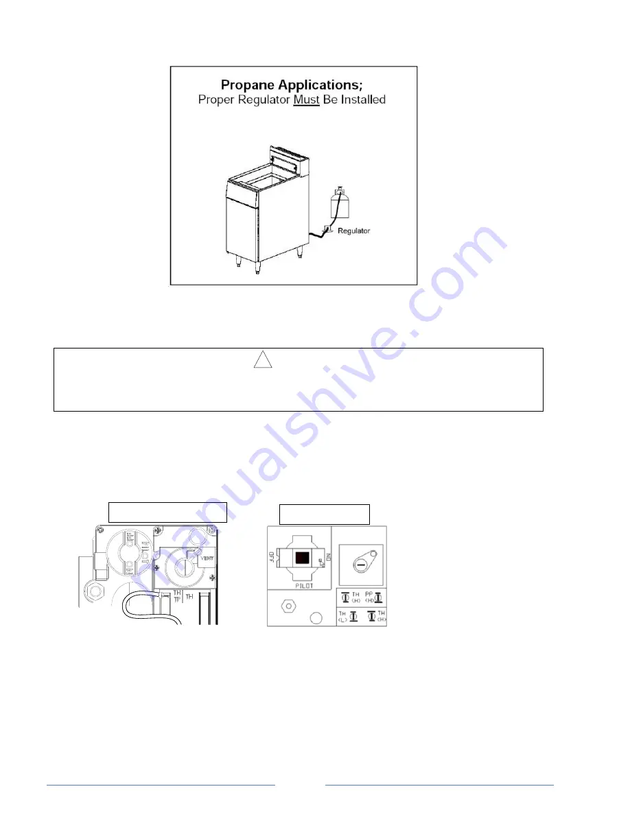
PHOTO 1 


O

PERATION


LIGHTING 

!

    CAUTION 

IF YOU SMELL GAS DURING THE LIGHTING PROCEDURE, IMMEDIATELY SHUT OFF THE GAS 
SUPPLY UNTIL THE LEAK HAS BEEN CORRECTED.


Open the burner compartment door and do the following: 

1. 

Turn thermostat to “OFF”  

2. 

Press down the knob of the combination gas valve, turn it counterclockwise to the “PILOT” position  

(shown), and continue to press the knob down. 


3.  While  pressing  the  knob  down,  use  a  lit  match  to  ignite  the  pilot.  Continue  to  press  the  knob  down  for 

about 30 seconds. If the pilot does not stay lit when the knob is released, repeat the lighting procedure 
and keep the knob down longer.  Adjustment of pilot flame may be necessary. 

4.  When the 

pilot stays lit, turn the knob counterclockwise to the “ON” position.  Do not press down on the 

knob in this step. 

5. 

Do NOT turn the thermostat “ON” until the frypot is filled with oil or solid shortening. 

6.  Once the frypot is filled with shortening, set the thermostat to the desired temperature 

Robert Shaw 7000BMVR 

Honeywell VS8200 

Содержание KF-F3-LP

Страница 1: ...Y DAMAGE INJURY OR DEATH READ THE INSTALLATION OPERATING AND MAINTENANCE INSTRUCTIONS THOROUGHLY BEFORE INSTALLING OR SERVICING THIS EQUIPMENT Please call the Service Department and ask for contact information for your local service company Model KF F3 NG KF F3 LP 3 Burners Fryer KF F4 NG KF F4 LP 4 Burners Fryer KF F5 NG KF F5 LP 5 Burners Fryer ...

Страница 2: ...t could result in injury product damage or property damage NOTICE This symbol refers to information that needs special attention or must be fully understood even though not dangerous WARNING FIRE HAZARD FOR YOUR SAFETY Do not store or use gasoline or other flammable vapors and liquids in the vicinity of this or any other appliance Keep area around appliances free and clear of combustibles Purchase...

Страница 3: ... of reliable trouble free operation For best results read this manual carefully RETAIN THIS MANUAL FOR FUTURE REFERENCE MODELS This manual is for Gas floor model Fryers with 40 lbs 50 lbs and 90 lbs capacity frypots The capacity is described on the serial plate that is located inside the front door on the left side Table of Contents Specifications 4 Installation 5 Operation 12 Cooking Hints 14 Cle...

Страница 4: ...Height in Gas Connection in Total BTU hr Crated Weight lbs A B C D E F G H I 3 burners fryer 15 5 14 0 30 3 14 0 47 2 34 7 6 0 4 2 7 0 90 000 150 4 burners fryer 15 5 14 0 30 3 14 0 47 2 34 7 6 0 4 2 7 0 120 000 162 5 burners fryer 21 0 18 0 34 3 18 0 47 2 34 7 6 0 4 2 7 0 150 000 209 B D ...

Страница 5: ...00 150 000 39 Propane 10 W C 5 30 000 150 000 52 Minimum supply pressure is 4 W C for natural gas and 10 W C for propane Orifice sizes are for units installed at altitudes between 0 and 2000 feet above sea level INSTALLATION NOTICE Installation must conform with local codes or in the absence of local codes with the National Fuel Gas Code ANSI Z223 1 Natural Gas Installation Code CAN CGA B149 1 or ...

Страница 6: ...rs are pre mounted on the base plates 1 Raise fryer sufficiently to allow legs or casters to be screwed into the base plate For safety shore up and support the fryer with an adequate blocking arrangement strong enough to support the load 2 Screw the four legs or casters to the plate on the bottom of the fryer When casters have been ordered the casters having a locking brake should be attached unde...

Страница 7: ...liance is moved to its original installed position WARNING When this appliance is installed with casters it must be installed with the casters supplied a connector complying with either ANSI Z21 69 or CAN CGA 6 16 and a quick disconnect device complying with either ANSI Z21 41 or CAN1 6 9 It must also be installed with restraining means to guard against transmission of strain to the connector as s...

Страница 8: ...8 Step 3 Flue Installation 1 Unpack the flue box and flue wrap 2 Slide the flue box over the flue and secure it with the two self tapping screws using a 5 16 socket 3 Slide the flue wrap over the flue ...

Страница 9: ...S FROM ADJACENT EQUIPMENT A FLAME GUARD IS ACCEPTABLE IF ALLOWED UNDER LOCAL CODE No additional side and rear clearance is required for service as the fryer is serviceable from the front WARNING Improper ventilation can result in personal injury or death Ventilation that fails to properly remove flue products can cause headaches drowsiness nausea or could result in death Unit Must be installed und...

Страница 10: ...e chart on page 4 If the fryer is being installed at over 2 000 feet altitude and that information was not specified when ordered contact the appropriate authorized Service Representative or the Service Department Failure to install with proper orifice sizing will result in poor performance and may void the warranty If applicable the vent line from the gas appliance pressure regulator shall be ins...

Страница 11: ...SSURES IN EXCESS OF 14 WC 1 2 PSIG or 3 45 kPa If the incoming gas pressure is in excess of 14 WC 1 2PSI 3 45 kPa a proper step down regulator will be required See PHOTO 1 for LP application Connect the gas supply directly to the 3 4 male NPT connector located near the lower left rear corner of the fryer When tightening the supply pipe be sure to hold the mating connector extending from the unit s...

Страница 12: ... knob down use a lit match to ignite the pilot Continue to press the knob down for about 30 seconds If the pilot does not stay lit when the knob is released repeat the lighting procedure and keep the knob down longer Adjustment of pilot flame may be necessary 4 When the pilot stays lit turn the knob counterclockwise to the ON position Do not press down on the knob in this step 5 Do NOT turn the th...

Страница 13: ... BURNERS WHEN THE FRYPOT IS EMPTY 7 To prevent burning or scorching the solid shortening keep the thermostat set at the lowest temperature until all the solid shortening between and above the tubes has been melted Additional solid shortening can then be added until the desired frying depth has been reached 8 Replace the basket support frame over the frypot heat tubes SHUTDOWN PROCEDURE Standby Tur...

Страница 14: ...od food CLEANING The equipment is constructed with the best quality materials and is designed to provide durable service when properly maintained To expect the best performance your equipment must be maintained in good condition and cleaned daily Naturally the frequency and extent of cleaning depends on the amount and degree of usage Following daily and more extensive periodic maintenance procedur...

Страница 15: ... residue from stainless steel use ordinary soap and water with or without detergent applied with a sponge or cloth Dry thoroughly with a clean cloth Never use vinegar or any corrosive cleaner To remove grease and food splatter or condensed vapors that have baked on the equipment apply cleanser to a damp cloth or sponge and rub cleanser on the metal in the direction of the polishing lines on the me...

Страница 16: ... contact your Service Representative for reliable service dependable advice or other assistance and for genuine factory parts All units are adjusted at the factory In case of problems in operation at initial installation check type of gas and manifold pressure and compare with information listed on the serial plate A mill voltage circuit diagram is located inside the front door of the fryer and al...

Страница 17: ...lace adjustment screw cap CHECKING AND ADJUSTING CALIBRATION OF THERMOSTAT All thermostat controls are carefully calibrated at the factory i e the dial is properly set to control appliance temperatures accurately Only a qualified appliance service technician should perform this adjustment 1 To check appliance temperatures use a thermocouple type temperature test instrument or reliable thermometer ...

Страница 18: ...ted Combination gas valve is in OFF position Pilot gas not adjusted properly Gas supply to unit off Bad thermopile Dirty thermopile connections at combination gas valve or high limit Clogged orifice Draft condition Air in gas line Improper ventilation system Pilot produces carbon deposits Unit connected to wrong gas supply Pressure not adjusted correctly Pilot gas not adjusted correctly Burners pr...

Страница 19: ...19 Wiring Diagram ...

Страница 20: ...acement parts may be ordered either through a Authorized Parts Distributor or a Authorized Service Agency When ordering parts please supply the Model Number Serial Number Part Number and Description Index of Part Diagrams Page Number Description 21 Gas Parts for 3 4 and 5 tube fryer 22 Tank Parts for 3 4 and 5 tube fryer 22 Other parts Legs Casters baskets doors magnet ...

Страница 21: ... Nat _Invensys 4 400146 1 Combination valve LP _Invensys 4 400242 1 Combination Valve Nat _Honeywell 4 400246 1 Combination valve LP _Honeywell 5 400070 1 Tubing fryer pilot 10 300031 ea Burner Fryer 11 400043 1 Safety thermopile 18 12 300034 ea Orifice 39 Nat as part of kit 266003 12 300035 ea Orifice 52 LP as part of kit 266002 14 400046 1 Thermostat High limit 450F 15 400047 1 Pilot 3 way ...
Страница 22: ...ryer 400076 1 Flue top removable 4 tube fryer 400077 1 Flue top removable 5 tube fryer 6 400078 1 Flue wrap top removable 3 and 4 tube fryer 400079 1 Flue wrap top removable 5 tube fryer not shown Other Parts Key Part Number Description 1 100106 Door assembly complete 3 and 4 tube 2 100137 Door assembly complete 5 tube 3 C400000 Leg Kit 6 adjustable set of 4 with mounting hardware 4 C400108 Caster...

Отзывы: