Switch Configuration
2
Keysight U7108x and U7110x Operating and Service Manual
21
Electronic Position Indicators
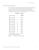
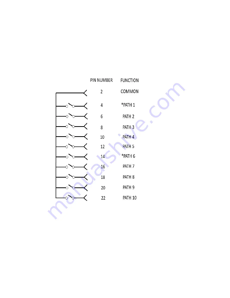
The electronic position indicators consist of optically isolated, solid state relays which are driven by
photo-electric sensors coupled to the mechanical position of the RF path’s moving elements (see
). The circuitry consists of a common which can be connected to an output
corresponding to each RF path. If multiple RF paths are engaged, the position indicator
corresponding to each closed RF path will be connected to common. The solid state relays are
configured for AC and/or DC operation. The electronic position indicators require that the supply
(24 Vdc) be connected to pin 1 and ground connected to pin
23
.
Figure 2-2
Pin configuration for indicator function
*Paths 1 and 6 are not connected for U7108x
Содержание U7108 Series
Страница 1: ...Keysight U7108x and U7110x Series Coaxial Multiport Switches Operating and Service Manual ...
Страница 6: ...6 Keysight U7108x and U7110x Operating and Service Manual THIS PAGE HAS BEEN INTENTIONALLY LEFT BLANK ...
Страница 8: ...8 Keysight U7108x and U7110x Operating and Service Manual THIS PAGE HAS BEEN INTENTIONALLY LEFT BLANK ...
Страница 10: ...10 Keysight U7108x and U7110x Operating and Service Manual THIS PAGE HAS BEEN INTENTIONALLY LEFT BLANK ...
Страница 12: ...12 Keysight U7108x and U7110x Operating and Service Manual THIS PAGE HAS BEEN INTENTIONALLY LEFT BLANK ...
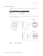
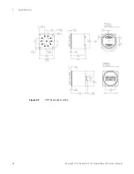
Страница 26: ...3 Specifications 26 Keysight U7108x and U7110x Operating and Service Manual Figure 3 2 U7110x product outline ...

