U3042AE16
Theory of Operation
Theory of Operation
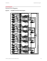
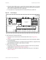
The following is a description of the operation of the test set. Reference the test set block
diagrams shown in
. This section assumes the user has a general
understanding of couplers, switches, and network analyzers.
RF Coupler/Bridges
The test set uses sixteen coupler/bridges (5087-7716) on the front panel for RF Test
Ports 5 to 20. The coupler/bridges provide the signal separation of the source and receiver
paths, using resistor networks. The test set ports can receive from or stimulate a signal to the
DUT.
The RF Test Ports are 3.5 mm male connectors. The coupling factor is approximately -16
dB for the Coupled Arm (minimum -22 dB and max -12 dB at 26.5 GHz). The insertion
loss through the CPLR THRU path is typically < 4 dB at 26.5 GHz for the coupler. Do not
use excessive RF power or DC voltage, or damage may occur to the internal resistors.
RF Switch Components
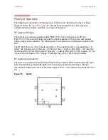
The test set uses sixteen solid-state switches that have internal 50 Ohm terminations for each
path. The switches select the RF paths from the analyzer’s source and receiver through
interconnect cables to the test set. Network analyzer Ports 1 to 4 and test set port paths 5 thru
20.
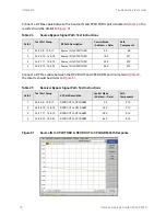
Figure 5
6
Switch
66
User's and Service Guide U3042-90012


