background image

Security Features and Document of Volatility

SSD Removal & Installation Procedures

16

6

SSD Removal & Installation Procedures

This chapter describes the procedures for physical removal and installation of 

the instrument’s Solid-State Disk Drive assembly (SSD). Removal of the SSD is 

an alternate method for instrument sanitization, in addition to the function 

“Erase SSD” on page 11

 (which does 

not

 require removal of the SSD and may 

be considered sufficient to sanitize the instrument).
When the instrument is returned to the secure location, use the installation 

procedure to re-install the SSD
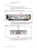
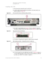
To remove or install the SSD, use the following procedures. The numbered 

items in the figures correspond to the step numbers in the procedure.

 CAUTION 

Before removing or installing the SSD Assembly, ensure that the instrument’s 

power is turned off.

“Removing the SSD” on page 17

“Installing the SSD” on page 18

Содержание N5192A UXG X-Series

Страница 1: ...Security Features and Document of Volatility Keysight N5192A 94A UXG X Series Agile Vector Adapter ...

Страница 2: ...computer software documentation No additional government requirements beyond those set forth in the EULA shall apply except to the extent that those terms rights or licenses are explicitly required from all providers of commercial computer software pursuant to the FAR and the DFARS and are set forth specifically in writing elsewhere in the EULA Keysight shall be under no obligation to update revis...

Страница 3: ...il subscribe to Keysight Email Updates http www keysight com find emailupdates Information on preventing instrument damage can be found at http www keysight com find PreventingInstrumentRepair Is your product software up to date Periodically Keysight releases software updates to fix known defects and incorporate product enhancements To search for software updates for your product go to the Keysigh...

Страница 4: ... Removal Procedures 11 Erase SSD 11 Clear Persistent State Information 12 Clear Most Mode States and Persistent State Information 12 Multi box Sync Setup 13 LO Control Setup 13 LAN Setup 14 Removal or Replacement of Solid State Disk Drive SSD 14 6 SSD Removal Installation Procedures 16 Removing the SSD 17 Installing the SSD 18 7 Secure Display Restricted Display 19 Secure Display 19 Restricted Dis...

Страница 5: ... local Keysight office is available via the internet at http www keysight com find assist If you do not have internet access please contact your designated Keysight representative N O T E In any correspondence or telephone conversation refer to the instrument by its model number and full serial number With this information the Keysight representative can determine whether your unit is still within...

Страница 6: ...dditional information go to http www keysight com find security IMPORTANT Be sure that all information stored by the user in the instrument that needs to be saved is properly backed up before attempting to clear any of the instrument memory Keysight Technologies cannot be held responsible for any lost files or data resulting from the clearing of memory Be sure to read this document entirely before...

Страница 7: ...o meet the requirements specified in DoD 5220 22 M National Industrial Security Program Operating Manual NISPOM Chapter 8 Sanitization As defined in Section 8 301b of DoD 5220 22 M National Industrial Security Program Operating Manual NISPOM sanitization is the process of removing the data from media before reusing the media in an environment that does not provide an acceptable level of protection...

Страница 8: ... Operation Data Retained When Powered Off Purpose Contents Data Input Method Location in Instrument and Remarks Sanitization Procedure 1 Main Memory DRAM 1 GByte Yes No Firmware operating memory User data Operating system CPU board not battery backed Volatile memory Turn off instrument power 2 Main Memory Flash 512 MByte partitioned as follows 200 MByte Boot Main firmware image Operating system 50...

Страница 9: ...RAM 18 MByte Yes No Stores Loaded list points etc Operating system DAC Board Volatile memory Turn off instrument power 7 DAC Board Memory EEPROM 16 MByte No Yes Factory calibration data None DAC Board None required no user data 8 Microdeck Board Memory EEPROM 6 MByte No Yes Factory calibration data None Microdeck Board None required no user data 9 Infrastructure Board Memory EEPROM 16 MByte No Yes...

Страница 10: ...memory See item 2 above User saved data Instrument Rear Panel Remove SSD Assembly from instrument and store securely For details of procedure see Removal or Replacement of Solid StateDisk Drive SSD on page 14 11 10 GByte Ethernet Interface Board Memory EEPROM 16 MByte No Yes Factory Calibration Data None Rear Panel Board None required no user data Table 4 1 Base Instrument Memory Component Type an...

Страница 11: ...on page 14 Removal or Replacement of Solid State Disk Drive SSD on page 14 CAUTION These functions do not erase or sanitize external media connected to the instrument s USB ports Erase SSD This function erases all user files such as PDW files and user correction files from the instrument s SSD using the ATA command SECURITY ERASE UNIT with the Erase Mode parameter set to Normal For more details of...

Страница 12: ...d Persistent State Information This command sets most states of the instrument back to their factory default settings including all mode states and states that are not normally affected by instrument power on preset or RST This also includes the current mode which will be set to Normal The following key sequence or SCPI command can be used to set operating states that are not affected by an instru...

Страница 13: ...trol Setup N O T E With the exception of Erase SSD no other feature defaults these values including the actions of Persistent System Settings SYSTem PRESet PERSistent and All Settings SYSTem PRESet ALL This key sequence or command sets the LO Control settings to their factory default settings The following table shows the key sequence or SCPI command that can be used to set their values to their f...

Страница 14: ...libration data is still available Optionally an unclassified replacement SSD may be installed without compromising the instrument sanitized state This section describes how to sanitize an instrument by physical removal and optional replacement of the SSD Refer to the flowchart in Figure 5 1 below for details of how to perform this procedure For the procedure on how to remove the SSD Assembly flow ...

Страница 15: ...Features Document of Volatility 15 Memory Clearing Sanitization and Removal Procedures Removal or Replacement of Solid State Disk Drive SSD Figure 5 1 Flowchart for Instrument Sanitization Process by SSD Removal ...

Страница 16: ...e function Erase SSD on page 11 which does not require removal of the SSD and may be considered sufficient to sanitize the instrument When the instrument is returned to the secure location use the installation procedure to re install the SSD To remove or install the SSD use the following procedures The numbered items in the figures correspond to the step numbers in the procedure CAUTION Before rem...

Страница 17: ...igure 6 1 Figure 6 1 Instrument Rear Panel SSD Assembly Location 3 Turn the thumbscrew on the SSD panel as shown in Figure 6 2 below to release the SSD Assembly from the rear panel If the thumbscrew is too tight to turn by hand use a TORX T15 screwdriver to loosen it Figure 6 2 Removable SSD Assembly details 4 Pull the U shaped handle attached to the SSD Assembly to remove the drive from the instr...

Страница 18: ...ly Location 3 Use the U shaped handle see Figure 6 5 that is attached to the SSD Assembly to align the instrument SSD slots see Figure 6 4 with the SSD Figure 6 4 Align with Instrument SSD Slots 4 Push the U shaped handle to place the SSD into the instrument Figure 6 5 SSD Assembly details U Shaped Handle Thumbscrew 5 Turn the thumbscrew on the SSD panel as shown in Figure 6 5 above to secure the ...

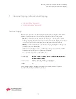
Страница 19: ... instrument power also restores the display Note that the current instrument state may be the last state before rebooting Off This selection blanks the instrument s display hiding the settings and disabling the front panel keys When Secure Display is active all front panel keys are disabled and the display is blank except for the advisory message SECURE DISPLAY ACTIVATED Once Secure Display has be...

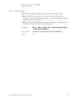
Страница 20: ...restricted display blanking the frequency The keys that access Frequency and User Amplitude Phase and Time Corrections are disabled Off This selection turns off the secure restricted display mode allowing the instrument s display to show the current frequency Key Sequence System More Display More Activate Restricted Display Confirm Restricted Display SCPI Command SYSTem SECurity DISPlay RESTricted...

Страница 21: ...moval Installation Procedures or the Service Guide If the Processor assembly has been removed proceed as in Table 8 1 below Table 8 1 Assembly Disposal Procedures Assembly Procedure Processor CPU Board Discard the processor board and send the instrument to a repair facility A new Processor Board will be installed then the instrument will be repaired and calibrated If the instrument is still under ...

Страница 22: ...tals 69 documents odaa ODAA 20Process 20Manual 20Version 203 2 pdf ver 2018 11 29 102431 710 The document may also be found by using the search feature on the Defense Security Service DSS website https www dcsa mil 3 Greenliant NANDrive Security Erase Feature Purge Command Specification This Application Note may be obtained in PDF format from Greenliant Systems Ltd by contacting the company via th...

Страница 23: ... Volatility 23 References 6 Service Guide Keysight Technologies Inc Part Number N5191 90019 To obtain a copy of this document contact your local Keysight office as detailed in Contacting Keysight Sales and Service Offices on page 5 ...

Страница 24: ...This information is subject to change without notice Keysight Technologies 2017 2020 Edition 1 January 2020 N5191 90018 www keysight com ...

Отзывы: