background image

10

Keysight MIPI M-PHY Frame Generator User Guide

2

Test Instrument Setup


Frame Generator Setups

Three setups are possible, which use different M-PHY generators:
• J-BERT M8040A MIPI

®

 M-PHY Generator

• J-BERT  BIT-3000 DSGA MIPI

®

 M-PHY Generator

• BIT-3000 DSGA MIPI

®

 M-PHY Generator

These setups, and which tests they are suitable for, are described in more 

detail below.

J-BERT M8040A MIPI

®

 M-PHY Generator

To use this setup, select “M8040A” as the “Instrument” in the Connection 

window of the software and leave “Low speed analyzer (DSGA)” as OFF. 

For more details, see 

Connecting to the Instruments

 on page 25.

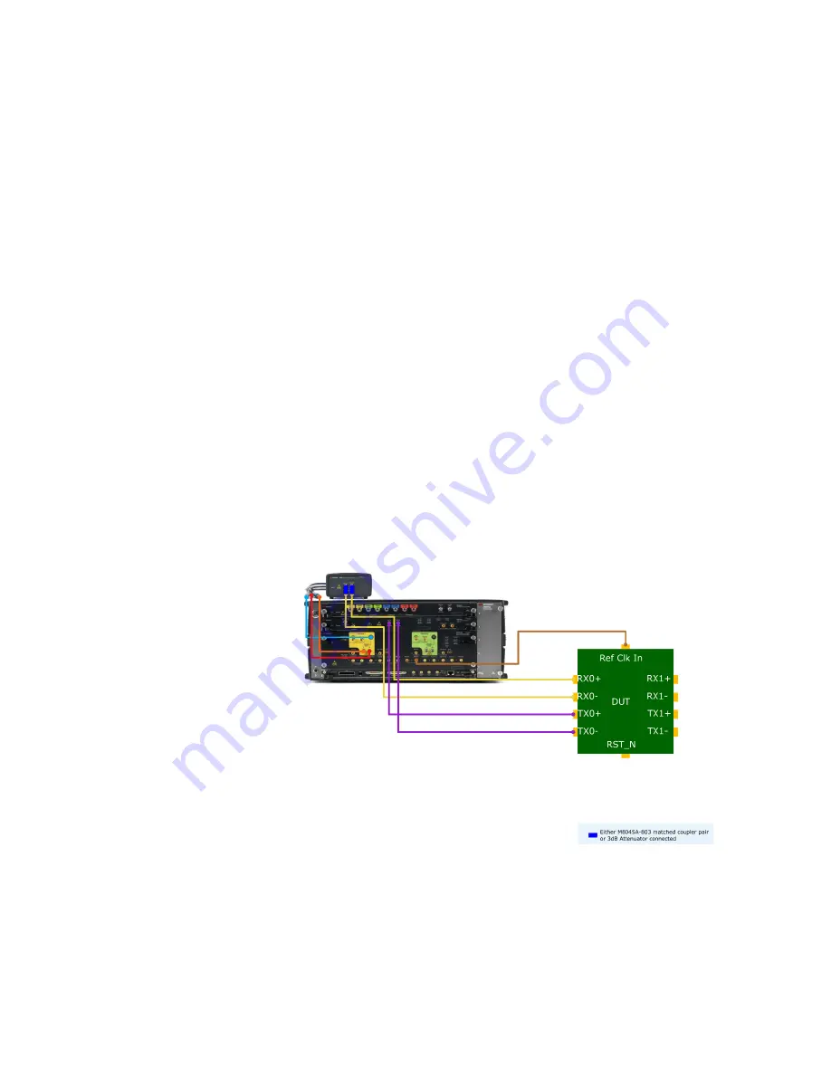
This system configuration (

Figure 1

) requires only the M8040A, which 

works as a generator and as an error detector if necessary. The small 

device on top of the M8040A in the connection diagram is the M8040's 

remote head, which is its output amplifier.

Figure 1

MIPI

®

 M-PHY Frame Generator hardware setup for J-BERT M8040A

Содержание MIPI M-PHY

Страница 1: ...User Guide Keysight MIPI M PHY Frame Generator ...

Страница 2: ...nment requirements beyond those set forth in the EULA shall apply except to the extent that those terms rights or licenses are explicitly required from all providers of commercial computer software pursuant to the FAR and the DFARS and are set forth specifically in writing elsewhere in the EULA Keysight shall be under no obligation to update revise or otherwise modify the Software With respect to ...

Страница 3: ...3000 DSGA MIPI M PHY Generator 11 BIT 3000 DSGA MIPI M PHY Generator 12 Setting Up the Instruments 14 3 Installing and Updating the Software Software Update 16 Software Installation 17 4 Starting and Registering the Software Starting Unregistered Software 20 Starting Registered Software 21 5 Using the Software General Features 24 Connecting to the Instruments 25 J BERT M8040A MIPI M PHY Generator ...

Страница 4: ... Icon 33 Restart Icon 34 Reset DUT Icon 34 Protocol Tab 34 Pattern Tab 39 Voltage Levels Tab 43 Data Rates Tab 46 Skew Tab 48 Jitter Tab 49 Analysis Tab 51 Global Outputs Switch 57 Sequence State Switch 57 Using UniPro Scripts 58 Setting Up the UniPro Test Mode 58 Working in the UniPro Test Mode 62 6 Troubleshooting Support Information 66 Using Logs 67 7 Appendix A Acronyms and Abbreviations ...

Страница 5: ...Keysight MIPI M PHY Frame Generator User Guide 1 Introduction Overview 6 ...

Страница 6: ... Mode and retrieve the Frame and Error Counters The Frame Generator is a flexible tool for trouble shooting and debugging It complements the full Test Automation Software which provides automated physical layer compliance tests and device characterization The Frame Generator generates the data sequences and allows pattern changes as well as the control of signal levels data rate and timing paramet...

Страница 7: ...troduction 1 Document History First Edition November 2021 The first edition of this user guide describes functionality of software version MPhy_Frame Generator_N5991_1 0 0 or higher which is based on the MIPI Alliance Specification for M PHY Version 5 0 ...

Страница 8: ...8 Keysight MIPI M PHY Frame Generator User Guide 1 Introduction ...

Страница 9: ...Keysight MIPI M PHY Frame Generator User Guide 2 Test Instrument Setup Frame Generator Setups 10 Setting Up the Instruments 14 ...

Страница 10: ...etail below J BERT M8040A MIPI M PHY Generator To use this setup select M8040A as the Instrument in the Connection window of the software and leave Low speed analyzer DSGA as OFF For more details see Connecting to the Instruments on page 25 This system configuration Figure 1 requires only the M8040A which works as a generator and as an error detector if necessary The small device on top of the M80...

Страница 11: ...ns However it cannot be used to test bursts With the M8040A it is also possible to test two receiver channels of the DUT simultaneously J BERT M8040A BIT 3000 DSGA MIPI M PHY Generator To use this setup select M8040A as the Instrument in the Connection window of the software and change Low speed analyzer DSGA to ON For more details see Connecting to the Instruments on page 25 This system configura...

Страница 12: ...er as bursts or continuous Also in this system configuration either a Keysight M8045A 803 matched coupler pair or a 3dB attenuator should be connected to the M8057 remote head output of the M8045 module We recommend using a 3dB attenuator with a minimum frequency range of 26 5GHz 2 pieces for each data lane BIT 3000 DSGA MIPI M PHY Generator To use this setup select Bit3000 as the Instrument in th...

Страница 13: ...Keysight MIPI M PHY Frame Generator User Guide 13 Test Instrument Setup 2 Figure 3 MIPI M PHY Frame Generator hardware setup for BIT 3000 DSGA ...

Страница 14: ...ablish the required connections between them Connect the instruments to the controller PC by LAN Establish all required cable connections between the instruments and the DUT Switch on the PC and instruments Start the Keysight IO VISA Connection Expert and check the connections for the instruments The use of the Connection Expert is described in the N5991 Getting Started Guide Set the correct IP ad...

Страница 15: ... Installing and Updating the Software Software Update 16 Software Installation 17 The MIPI M PHY Frame Generator software runs on the PC that controls the BERT If it is already installed on the PC and is not to be updated proceed to the next chapter ...

Страница 16: ...ware Update If you want to upgrade a previous version of the MIPI M PHY Frame Generator software please uninstall it from the PC during the installation of the new version when prompted by the setup program You may choose whether to uninstall just the program files or the user data as well ...

Страница 17: ...ller file MPhy_Frame Generator_N5991_Installer exe The welcome page of the setup program will open The second and third pages of the setup program will show the software license agreement Read it carefully and select I accept the terms of the License Agreement Then click Next to continue The Choose Install Location window will open Either confirm the given path or click the Browse button to select...

Страница 18: ...18 Keysight MIPI M PHY Frame Generator User Guide 3 Software Installation and Update ...

Страница 19: ...g the Software Starting Unregistered Software 20 Starting Registered Software 21 Start the software with a double click of the left mouse button on the M PHY Frame Generator N5991 icon Alternatively start the application from BitifEye M PHY N5991 M PHY Frame Generator N5991 ...

Страница 20: ... the software without a valid license opens the No license found dialog window To obtain a valid license use the BitifEye License Manager BLM portal https licensing bitifeye com add the license to your PC and activate it For detailed instructions on how to use the BLM please refer to the manual BitifEye License Manager User Guide ...

Страница 21: ...MIPI M PHY Frame Generator User Guide 21 Starting and Registering the Software 4 Starting Registered Software If the software is already registered it starts automatically Proceed to Chapter 5 Using the Software ...

Страница 22: ...22 Keysight MIPI M PHY Frame Generator User Guide 4 Starting and Registering the Software ...

Страница 23: ... 60 Once the software has been installed the N5991 M PHY Frame Generator icon will appear on the desktop Double click to start the software Alternatively start the application from BitifEye M PHY N5991 M PHY Frame Generator N5991 The setup that you are going to use can be configured using the Connection window while the tabs in the Signal window are used to select the MIPI M PHY signal parameters ...

Страница 24: ...Clicking ABOUT in the top right corner will open a panel giving details of the version of the Frame Generator that is running and the corresponding software license see Figure 4 Figure 4 Example ABOUT window Click View Changelog there to view the changelog describing changes that have been made to the software Clicking Copy to Clipboard copies details about the software version and the license to ...

Страница 25: ...A First choose the BERT either M8040A from Keysight or BIT 3000 from BitifEye using the Instrument dropdown menu according to the setup you want to use refer to Chapter 2 Test Instrument Setup The connection diagram in the right half of the window will change depending on what you select If you set Offline Connection to ON you can configure the instruments without them being physically connected T...

Страница 26: ...P address If Advanced is checked specify the Instrument address using TCP IP As described in the section Frame Generator Setups on page 10 a BIT 3000 DSGA can be added to the setup Set Low speed analyzer DSGA to ON and specify the DSGA address If the DUT has a reset and it is to be used set DSGA Trigger to ON Finally there is the possibility to use results of level calibrations run in ValiFrame Cl...

Страница 27: ...Keysight MIPI M PHY Frame Generator User Guide 27 Using the Software 5 Figure 6 MIPI M PHY N5991 Frame Generator CONNECTION window for BIT 3000 ...

Страница 28: ...Disconnecting from the Instruments When you want to change the configuration after running some tests return to the Connection window by clicking first the CONNECTION button and then Disconnect The message Disconnection from instruments successful should appear in the log ...

Страница 29: ...indow will open This is indicated by the SIGNAL button on the task bar turning blue see Figure 7 and the CONNECTION button turning white Figure 7 MIPI M PHY N5991 Frame Generator SIGNAL window The Signal window is very flexible and can be arranged as you wish simply by dragging and dropping the tabs White lettering on a blue background shows which tab is visible Figure 8 shows an alternative arran...

Страница 30: ...e Software Figure 8 SIGNAL window with just the Pattern Tab visible The signal window consists of seven icons just below the task bar Settings View Apply Abort Break Restart Reset DUT and seven tabs Protocol Pattern Voltage Levels Skew Jitter Data Rates Analysis ...

Страница 31: ...ample if you have configured the setup for a particular task or DUT you can save this configuration for future use Similarly if you have already saved a particular configuration you can load it to use it again thus saving time It is also possible to reset the configuration to the default values View Icon As described on page 29 you can drag and drop the tabs to position them as you want on the scr...

Страница 32: ...The pop up menus for the View Icon If the menu point floatable tabs is enabled see Figure 9 you can drag each tab so that it pops out into its own separate window see Figure 10 It can be docked back on to the others by dragging it back towards them so that it turns into a tab again ...

Страница 33: ...ort Icon The Abort Icon can be used to abort application of the tabs to the instruments if necessary This icon is grayed out disabled until the Apply Icon has been clicked Break Icon The function of the Break Icon is related to the Pattern tab In some patterns the first block of the generator sequence is 1 Sleep manual This means that the instrument does not step into the link training until manua...

Страница 34: ...om the beginning click RESTART The instrument goes back to the first block in the generator sequence In many cases this is 1 Sleep manual and link training will not resume until forced to with BREAK This icon is grayed out disabled until the Apply Icon has been clicked Reset DUT Icon The function of the Reset DUT Icon is related to the connection configuration If the Trigger Out of the DSGA is con...

Страница 35: ...ator User Guide 35 Using the Software 5 Protocol Tab The Protocol Tab see Figure 11 provides access to the M PHY specific settings that you can change The values of the parameters will vary according to the DUT Figure 11 Protocol Tab ...

Страница 36: ...umber of SYNC pattern symbols before the burst starts For HS mode the Prepare Length will be followed by a SYNC sequence D10 5 D26 5 In HS burst and PWM burst modes the SYNC sequence is followed by the payload The payload starts with MARKER0 MK0 HS Sync Range Select either Fine or Coarse for the HS Sync Range For Fine the duration of the HS sync sequence TSYNC is equal to the HS Sync Length TSYNC ...

Страница 37: ...s of the MIPI Alliance Specification for M PHY Version 5 0 document PWM Sync Range Select either Fine or Coarse for the PWM Sync Range For Fine the duration of the HS sync sequence TSYNC is equal to the HS Sync Length TSYNC SYNC_length For Coarse TSYNC min 2SYNC_length 214 For more details see Table 7 PREPARE SYNC and ADAPT Attribute and Dependent Parameter Values of the MIPI Alliance Specificatio...

Страница 38: ...n Table 2 Table 2 Sequence examples using GuardBand Word Size Sync Pattern Settings Word Size bits The Word Size can be selected as 8 10 16 or 20 bits Sync Pattern D10 5 and D26 5 are the default sync symbols used for the sync pattern The symbols with at least seven transitions inside the symbol of nine possible transitions are used for the sync sequence Mode Effect on Prepare Length Effect on Syn...

Страница 39: ...quence with Manual Break Set to ON to automatically add a Pause block to the sequence and turn off the Global Output of the M8040A The DUT will only receive the signal after you have pressed Break A limitation of this feature is that the DUT loses its HS termination as soon as the Global Output is off Reset DUT on starting Sequence This button is enabled if in the Connection window the buttons Low...

Страница 40: ... select Script editor from the dropdown menu you can load various sequence files using the symbol marked in Figure 12 The default location of the sequence files is C ProgramData BitifEye ValiFrameK1 MPhy Pattern Each file defines a sequence which is built up of one or more blocks Figure 12 Pattern Tab Script Editor window The script editor allows you to edit the training sequences and patterns usi...

Страница 41: ...ve the sequence or to save it under another name or somewhere else Save As If you mark data and right click in the Script Editor field a list of possible conversions will pop up see Figure 13 This is a handy conversion tool if you want to convert numbers between different numbering systems Binary to Hex and Hex to Binary are just generally useful In M PHY the numbering system is 8b 10b the remaini...

Страница 42: ...utton opens an additional window see Figure 14 in which the blocks are listed in terms of commands and data instead of macros The Generator Sequence and the Analyzer Sequence are also listed Figure 14 Pattern Tab Process Script window If you mark part of the content of the Process Script or Post Process Script field and then right click a menu pops up that you can use to cut copy or paste the mark...

Страница 43: ...5 Clicking the Post Process Script button opens another window see Figure 15 in which the blocks are listed as data you can see exactly what the data looks like in hexadecimal notation that will be sent to the instruments Figure 15 Pattern Tab Post Process Script window ...

Страница 44: ...the buttons directly above the slider The levels can be set for each data channel individually and also for the reference clock Changes that you make in the Voltage Levels Tab are applied immediately You do not have to click Apply Figure 16 Voltage Levels Tab Clock channel showing the slider for the Offset Parameters in the Voltage Levels Tab Channel Choose either Clock or a data channel from the ...

Страница 45: ...vel Low Level or in terms of Amplitude Offset Range of Amplitude From 35mV to 630mV Default 200mV The range of High Level is defined as 2 3 Vterm 0 95 V High Level Vterm 2 V The range of Low Level is defined as 2 3 Vterm 1 V Low Level Vterm 1 95 V The range of Offset is defined as 1 2 High Level Low level Equalization Settings The equalization can be specified in terms of De Emphasis Post Cursor 1...

Страница 46: ...46 Keysight MIPI M PHY Frame Generator User Guide 5 Using the Software Figure 17 Voltage Levels Tab Data0 channel ...

Страница 47: ... Data Rates The parameter values can be entered numerically or by using the slider that appears when you click the corresponding parameter field You can set the minimum default or maximum level quickly by clicking the buttons directly above the slider Figure 18 Data Rates Tab Parameters in the Data Rates Tab Ref Clock Frequency Select from 19 2 26 38 4 and 52MHz for M8040A For BIT 3000 only the fi...

Страница 48: ...r hardware HS Data Rate Deviation ppm The deviation of the HS Data Rate from the nominal value Min 5000ppm Default 0 Max 5000ppm Clock Source Select Internal Clock 10MHz Reference Clock or 100MHz Reference Clock from the dropdown list Applied HS Data Rate The HS Data Rate value that is applied to the instrument HS Bit Multiplicator MPHY Gear 1 has a data rate lower than the minimum data rate of th...

Страница 49: ...tion Variation Speed The bit variability is a sinusoidal function that varies between the minimum PWM period and the maximum PWM period The period of this function is defined as variation speed A positive number defines how fast the PWM bit duration should change compared to the previous PWM bit The greater the number the slower the rate of change Example If the value is 10 then the sinusoidal fun...

Страница 50: ...nels Min 50ns Default 0 Max 50ns The parameter values can be entered numerically or by using the slider that appears when you click the corresponding parameter field You can set the minimum default or maximum level quickly by clicking the buttons directly above the slider Changes that you make in the Skew Tab are applied immediately You do not have to click Apply Figure 19 Skew Tab ...

Страница 51: ...ypes of jitter to be added to the signal The parameter values can be entered numerically or by using the slider that appears when you click the corresponding parameter field You can set the minimum default or maximum level quickly by clicking the buttons directly above the slider Changes that you make in the Jitter Tab are applied immediately You do not have to click Apply Figure 20 Jitter Tab ...

Страница 52: ...of the jitter in unit intervals UI manually by slider or by clicking the max min or default button Frequency Set the frequency of the jitter manually by slider or by clicking the max min or default button Random Jitter The types of random jitter areA LF Random Jitter ST Random Jitter with the following parameters Jitter Source Read only The source generating the jitter Enabled Switch to ON to appl...

Страница 53: ...y Parameters in the Analysis Tab Analysis Selector Select either Configuration or Analyzer First use Configuration to configure the setup of the analyzer then use Analyzer to control the analyzer while it is running The parameters displayed also depend on whether the Low Speed Analyzer DSGA is selected in the Connection window a Configuration for Analysis without the Low Speed Analyzer DSGA Ensure...

Страница 54: ... settings Custom CDR Settings Loop Bandwidth Set the bandwidth value of the analyzer CDR Min 2MHz Default 2MHz Max 20MHz Loop Selection Select the required loop from the dropdown list if more than one is available Transition Density Set the transition density of the CDR Min 0 Default 50 Max 100 Follow SYS Clock If ON the Analyzer Symbol Rate is a read only parameter and depends on what you have ch...

Страница 55: ...it Error Ratio Measurement when the DUT is working in loopback mode see Figure 22 In loopback mode the DUT will loop back the received test pattern Then the error detector compares the pattern returned by the DUT with the generated pattern to detect bit errors and compute the BER Figure 22 Analysis Tab Bit Error Ratio Measurement Reset This button sets the bit and error counters and the BER back t...

Страница 56: ...e clock of the TX side of the DUT and the analyzer clock must be in phase This is ensured by a common reference clock When the received bits are not synchronized with the pattern of the analyzer the computed BER will be very high In this case clicking on the Analyzer Auto Align button restarts the synchronization algorithm in the analyzer c Configuration for Analysis with the Low Speed Analyzer DS...

Страница 57: ...ire Select either Normal or Complement Threshold Voltage Min 800mV Default 100mV Max 800mV d Controlling the Analyzer with the Low Speed Analyzer DSGA connected Change Analysis Selector to Analyzer to control the Frame Error Ratio Measurement see Figure 24 when the DUT is working in the PACP Test Mode This test mode is explained in Section 5 7 15 of the UniPro specification version 1 8 The DUT is ...

Страница 58: ...atio back to zero Frame Error Ratio The ratio of the number of false or error frames to the total number of transmitted frames that is errors frames Get Counters When you click this button the data captured by the analyzer will be shown in the upper output panel and the Frame Counter and Error Counter values will be updated Frames Number of frames received by the DUT Errors Number of frame errors ...

Страница 59: ... have been encountered A description of any problem found will appear in the log window Sequence State Switch If you set the Sequence State switch to ON another parameter field opens to the right that shows the current state of the setup For example if the first block of the sequence is 1 Sleep the Sequence State might show 1 Sleep so you know which block of the sequence has been reached If the se...

Страница 60: ...attern Tab UniPro Script Generator window for Rx test mode Parameters in the UniPro Script Generator Window Sequence Generic Sequence The default Generic Sequence should be kept as M PHY_UniPro_BasicBlocks seq This sequence can be edited and the changes will propagate to all the generated sequences This sequence is a template it cannot be used directly Output Sequence Either set the path for the o...

Страница 61: ...e configured to transmit the signal in High Speed or Low Speed PWM GEAR 1 The DUT will transmit the signal in LS PWM This option is required for setups that include the DSGA as the analyzer error detector and cannot be used for the stand alone M8040A setup HS same as Rx The DUT will transmit the signal in the same HS gear as was used for the signal received by the DUT RxGear1A 1B 5A 5B The DUT wil...

Страница 62: ...r just one channel or all channels Tx Test Pattern The pattern currently supported is CRPAT Tx Gear Choose the gear for the Tx mode The available options are TxGear1A 1B 5A 5B and TxPwmGear1 Tx Equalization Choose 0dB 3 5dB or 6dB The selected values are reflected only in sequences for Gear 3 and above but if required the equalization block can be included in the configuration of Tx Gear 1 and Gea...

Страница 63: ...This defines the number of DIFP states before a PWM Burst That is the parameter sets the length of the LS Prepare state Min 0 Default 15 Max 15 STALL Time This defines the number of DIFN states after a HS data burst That is the parameter sets the length of the power saving Stall state between HS bursts Custom Packets This enables you to change the default values of the registers used in the defaul...

Страница 64: ...ACP Gap After Test Pattern Values as for Gap Before PACP Gap After Request Values as for Gap Before PACP Gap Between Bursts Min 1 Default 1300 Max 140000 Idle Line States These parameters are used to specify the duration of the different idle signals DIFP Differential positive voltage Min 0s Default 3 5ms Max 10s DIFN Differential negative voltage Min 0s Default 5ms Max 10s Sleep Power saving stat...

Страница 65: ...f wildcards The wildcards available are explained in the section Wildcards on page 66 The large panel gives the sequence in terms of blocks the generator sequence and the analyzer sequence See Figure 27 Figure 27 Pattern Tab After generating the UniPro Scripts Example If the sequence UniProRx HsGear Mode Amplitude Channel seq appears in the sequence field then to the left of that field the actual ...

Страница 66: ...lists the names of the wildcards that are supported for sequence names along with their possible values No wildcards are mandatory Table 3 Supported wildcards for sequence names and their possible values Wildcard Values Tab in which the value of the wildcard can be changed HsGear Gear1A Gear5B Data Rates Tab Mode Cont Burst Protocol Tab Amplitude Large Small Protocol Tab Channel Data0 DataAll For ...

Страница 67: ...Keysight MIPI M PHY Frame Generator User Guide 6 Troubleshooting Support Information 68 Using Logs 69 ...

Страница 68: ... software send an email to mipi support bitifeye com Remember to include details of the software version and license You can find these by clicking ABOUT in the main Frame Generator window see Figure 4 Clicking the Copy to Clipboard button copies these details to the clipboard so that you can easily paste this information into your e mail ...

Страница 69: ...Keysight MIPI M PHY Frame Generator User Guide 69 Software Installation and Update 6 Using Logs Right click the Log panel select Show Log File to view the logs and investigate the root cause of an issue ...

Страница 70: ...70 Keysight MIPI M PHY Frame Generator User Guide 6 Software Installation and Update ...

Страница 71: ...ysight MIPI M PHY Frame Generator User Guide 7 Appendix A Acronyms and Abbreviations This Appendix contains a list of acronyms and abbreviations used in the Keysight MIPI M PHY Frame Generator User Guide ...

Страница 72: ...rator and Analyzer DUT Device Under Test FIR Finite Impulse Response HiSLIP High Speed LAN Instrument Protocol HS high speed IO Input Output IP Internet Protocol J BERT Jitter Bit Error Ratio Tester LAN Local Area Network LS Low Speed LF Low Frequency MIPI Mobile Industry Processor Interface MK0 Marker Zero M PHY A high speed data communications physical layer protocol standard PC Personal Compute...

Страница 73: ...ADAPT Duration of ADAPT Sequence TCP Transmission Control Protocol TSYNC Duration of HS SYNC Sequence TTC Transition Time Converter Tx Transmitter UFS Universal Flash Storage UI Unit Interval UniPro Unified Protocol VISA Virtual Instrument System Architecture Vterm Terminated Voltage Acronym Definition ...

Страница 74: ...72 Keysight MIPI M PHY Frame Generator User Guide 7 Software Installation and Update ...

Страница 75: ...Keysight MIPI M PHY Frame Generator User Guide 75 ...

Страница 76: ...This information is subject to change without notice Keysight Technologies 2021 Edition 1 0 November 2021 www keysight com ...

Отзывы: