background image

126

Keysight M809256PB OIF CEI-56G Rx Test Automation Application User Guide

8

OIF CEI-56G LR PAM4 Calibrations


Common Calibrations

Amplitude Calibration

Overview

The Amplitude Calibration is performed to calibrate the Victim Generator’s 

Amplitude for the Transmitter Measurements for COM model.

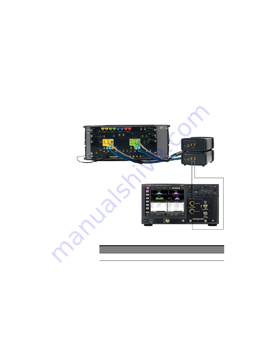
Connection Diagram

Connect the instruments as shown in 

Figure 94

.

Figure 94

Amplitude Calibration connections for LR

ID

Parameters

Refer to “

Calibration Parameters in Debug Mode

” on page 122.

Procedure

This calibration uses the QPRBS13-CEI pattern.

The Victim Generator Amplitude is set and measured for multiple 

Amplitudes.

Standard Name

Test ID

Long Reach

671100

Содержание M809256PB

Страница 1: ...User Guide Keysight M809256PB OIF CEI 56G Pre Compliance Rx Test Automation Application ...

Страница 2: ...ments beyond those set forth in the EULA shall apply except to the extent that those terms rights or licenses are explicitly required from all providers of commercial computer software pursuant to the FAR and the DFARS and are set forth specifically in writing elsewhere in the EULA Keysight shall be under no obligation to update revise or otherwise modify the Software With respect to any technical...

Страница 3: ...terfaces 12 Instrument Firmware Requirements 12 Required Configuration licenses 14 Installing the Software 18 Installing the License Key 23 Using Keysight License Manager 5 23 Using Keysight License Manager 6 24 3 Preparing to take Measurements Calibrating the Instruments 28 Starting the Test Application 29 Setting up the OIF CEI 56G Rx Test Application 36 Understanding Calibration Data Persistenc...

Страница 4: ...libration 59 UUGJ Calibration 62 BUJ Calibration 65 Stressed Eye Calibration 67 5 OIF CEI 56G VSR PAM4 Tests Test Parameters in Debug Mode 74 Parameters common for all tests 74 Common Parameter for VSR Host Input tests only 74 Parameters for Stressed Input Test 74 Parameters for Voltage Tolerance Test 75 Single lane Stressed Input Test 76 Multi lane Stressed Input Test 81 Voltage Tolerance Test 87...

Страница 5: ...nsmitter Measurements for COM Model 109 Rx Verification using COM model 111 7 OIF CEI 56G MR PAM4 Tests Test Parameters in Debug Mode 114 Parameters common for all tests 114 Parameters for Receiver Interference Tolerance Test 115 Parameters for Receiver Jitter Tolerance Test 115 Receiver Interference Tolerance Test 116 Receiver Jitter Tolerance Test 118 8 OIF CEI 56G LR PAM4 Calibrations Calibrati...

Страница 6: ...M model 144 Receiver Jitter Tolerance 146 Transmitter Measurements for COM Model 146 Rx Verification using COM model 148 9 OIF CEI 56G LR PAM4 Tests Test Parameters in Debug Mode 152 Parameters common for all tests 152 Parameters for Receiver Interference Tolerance Test 153 Parameters for Receiver Jitter Tolerance Test 153 Receiver Interference Tolerance Test 154 Receiver Jitter Tolerance Test 156...

Страница 7: ...ication User Guide 1 Introduction Overview 8 Related Documents 9 Contacting Keysight Technologies 10 To install the OIF CEI 56G Rx Test Application you require the installer file and the licenses necessary for the installation and for running various tests ...

Страница 8: ...R PAM4 CEI 56G MR PAM4 and CEI 56G LR PAM4 calibrations and tests The OIF CEI 56G specifies a 56Gb s electrical interface for use in the range 18 0 to 29 0 Gsym s with up to 10 0 dB loss at the Nyquist frequency including one connector For more details refer to Optical Internetworking Forum Clauses 16 17 and 21 of the OIF CEI 4 0 Common Electrical I O CEI Electrical and Jitter Interoperability Agr...

Страница 9: ...er 29 2017 IEEE Standard for Ethernet Amendment 2 Physical Layer Specifications and Management Parameters for 100 Gb s Operation Over Backplanes and Copper Cables M8070B documentation For more information about M8070B software refer to the M8070B documentation To locate the M8070B documents click Start Keysight M8070B Keysight M8070B Documentation Alternatively you may also visit www keysight com ...

Страница 10: ...ation User Guide 1 Introduction Contacting Keysight Technologies For more information on products applications or services associated with Keysight Technologies contact your local Keysight office The complete list is available at www keysight com find contactus ...

Страница 11: ... Guide 2 Installing the OIF CEI 56G Rx Test App System requirements 12 Installing the Software 18 As a prerequisite to installing the OIF CEI 56G Rx Test Application you require the necessary hardware along with installing certain softwares along with various licenses ...

Страница 12: ...8000 series Ver 6 5 0 0 or later M8070ADVB Advanced Measurement Package for M8000 Series Ver 1 1 550 2 or later M8195A soft front panel version 3 6 or M8196A soft front panel version 2 1 Microsoft Office 2010 or higher MATLAB Compiler Runtime R2017a 9 2 Installer Link http ssd mathworks com supportfiles downloads R2017a deploy ment_files R2017a installers win64 MCR_R2017a_win64_installer exe Updat...

Страница 13: ...ence Source NA M8054A M8195A M8196A 3rd party Noise Generator M8054A M8195A M8196A 3rd party Noise Generator Victim Error Detector M8046A DCI DUT Control Interface M8046A DCI DUT Control Interface M8046A DCI DUT Control Interface Clock Recovery M8046A 0A4 internal CDR N1076A N1076B N1077A N1078A M8046A 0A4 internal CDR N1076A N1076B N1077A N1078A M8046A 0A4 internal CDR N1076A N1076B N1077A N1078A...

Страница 14: ... channel NRZ data rate up to 32 64 Gbaud M8045A 0G3 Advanced jitter sources for receiver characterization license M8045A 0G4 De emphasis module wide license M8045A 0P3 PAM 4 encoding up to 32 Gbaud module wide license M8057A B Remote head for M8045A pattern generator 1 channel M8045A 801 Short cable 1 85 mm m to 1 85 mm m 0 15 m 699 ps delay 1 ps two are recommended for each differential data outp...

Страница 15: ...Bd to 32 GBd discontinued N1076B Electrical Clock Recovery N1076B 232 Supported input rates 125 MBd to 32 GBd N1077A Optical Electrical Clock Recovery N1077A 232 Supported input rates 50 MBd to 32 GBd N1078A Optical Electrical Clock Recovery N1078A 232 Supported input rates 125 MBd to 32 GBd Product Description M8070B System software for M8000 Series of BER test solutions M8070ADVB 1xx Advanced Me...

Страница 16: ...sis SW N1010AT 86100D 201 Advanced Waveform analysis N1010AT 86100D 9FP PAM N analysis software N1010AT 86100D SIM InfiniiSim DCA embedding de embedding of cables or fixtures OR choose FlexDCA R D package N1010100A Research and Development Package for FlexDCA DCA X mainframe minimum configuration Product Description N1060A 050 Two 50 GHz channels N1060A 232 Supported input rates 125 MBd to 32 GBd ...

Страница 17: ...09256PB software configuration Product Description M8049A 002 for VSR Host Module ISI Channel Board Nine Traces from 0 8 to 8 0 inches M8049A 003 for MR LR ISI Channel Board Seven Traces from 9 1 to 22 3 inches Product Description M809256PB 1xx RX Test Automation license for OIF CEI 56G VSR MR LR node locked transportable floating or USB license ...

Страница 18: ...lication can be downloaded from the Keysight website Download the installer file from www keysight com find m8000 To install the OIF CEI 56G Rx Test Automation Application 1 Double click the downloaded installer file on your PC The Installation Wizard for the Keysight OIF CEI 56G Rx Test Automation Application appears Figure 1 Installation wizard for the OIF CEI 56G Rx Test Application ...

Страница 19: ...on User Guide 19 Installing the OIF CEI 56G Rx Test App 2 2 Click Next The Keysight Software End User License Agreement window appears 3 Select Agree to agree to the license agreement and to enable the Next button Figure 2 License Agreement window 4 Click Next ...

Страница 20: ...eysight M809256PB OIF CEI 56G Rx Test Automation Application User Guide 2 Installing the OIF CEI 56G Rx Test App 5 On the window that appears click Install Figure 3 Window to begin Application installation ...

Страница 21: ... Test Automation Application User Guide 21 Installing the OIF CEI 56G Rx Test App 2 6 Once the installation of the OIF CEI 56G Rx Test Automation Application begins its status is displayed Figure 4 Window displaying installation status ...

Страница 22: ...tomation Application User Guide 2 Installing the OIF CEI 56G Rx Test App 7 Once the installation is complete the following window appears Click Finish to complete the installation and exit the wizard Figure 5 Window indicating end of installation ...

Страница 23: ... Launch Keysight License Manager on your machine where you wish to run the Test Application and its features 2 Copy the Host ID that appears on the top pane of the application Note that x indicates numeric values Figure 6 Viewing the Host ID information in KLM 5 To install one of the procured licenses using Keysight License Manager 5 application 1 Save the license files on the machine where you wi...

Страница 24: ...ing Documentation Using Keysight License Manager 6 To view and copy the Host ID from Keysight License Manager 6 1 Launch Keysight License Manager 6 on your machine where you wish to run the Test Application and its features 2 Copy the Host ID which is the first set of alphanumeric value as highlighted in Figure 8 that appears in the Environment tab of the application Note that x indicates numeric ...

Страница 25: ...he license files on the machine where you wish to run the Test Application and its features 2 Launch Keysight License Manager 6 3 From the Home tab use one of the options to install each license file Figure 9 Home menu options to install licenses on KLM 6 For more information regarding installation of procured licenses on Keysight License Manager 6 refer to Keysight License Manager 6 Supporting Do...

Страница 26: ...26 Keysight M809256PB OIF CEI 56G Rx Test Automation Application User Guide 2 Installing the OIF CEI 56G Rx Test App ...

Страница 27: ... Starting the Test Application 29 Setting up the OIF CEI 56G Rx Test Application 36 Overview on Channel Operating Margin COM 50 NOTE Ensure that all instruments specified in Required Configuration licenses on page 14 are defined in the Keysight Connection Expert on the PC where the OIF CEI 56G Rx Test Automation Application is installed ...

Страница 28: ...Test Automation Application 1 Disconnect all the cables that may be connected to the FlexDCA oscilloscope 2 From the main menu of the FlexDCA N1000 Series System Software select Tools Calibrations 3 Follow the on screen instructions to perform calibrations If the calibrations are not performed warning messages are logged for each calibration performed from the M8070B software To know how to perfor...

Страница 29: ...ion make sure that Keysight M8070B software and FlexDCA N1000 Series System Software are online and active on the respective instruments For calibrations and tests the VSR standard options require mated compliance boards and ISI channel boards whereas the MR LR standard options require ISI channel boards only Ensure that proper connections with the testing instruments are established and that the ...

Страница 30: ... the Start menu of the Win10 OS click Keysight M8070B Applications Launch Keysight M809256PB Figure 10 Launching the OIF CEI 56G Rx Test Application NOTE If you do not see Keysight M809256PB listed on the Start menu the OIF CEI 56G Rx Test Automation Application has not yet been installed on the PC Refer to Installing the Software on page 18 for installation instructions ...

Страница 31: ...ftware only is running online the OIF CEI 56G Rx Test Automation Application launches after automatically getting connected to the M8070B software If the OIF CEI 56G Rx Test Automation Application detects more than one instance of the M8070B software running the Connect to M8070B System Software for M8000 Series of BER Test Solutions M8070 window appears Figure 11 Connecting to M8070B if multiple ...

Страница 32: ...ress to connect to M8070B access the SCPI Server Information window by clicking Utilities SCPI Server Information from the main menu of the Keysight M8070B software Figure 12 SCPI Server Information window on the M8070B Software If the BERT device is online and defined in the Keysight Connection Expert click Select from Keysight Connection Expert favorites The VISA address list defined in the Keys...

Страница 33: ...System Software for M8000 Series of BER Test Solutions M8070 window The IDN field displays the instrument name Figure 13 IDN field displaying successful connection to M8070B 4 Click OK to establish connection with M8070B and to launch the OIF CEI 56G Rx Test Automation Application If a connection is not established the application fails to launch ...

Страница 34: ...IF CEI 56G Rx Test Automation Application User Guide 3 Preparing to take Measurements The OIF CEI 56G Rx Test Automation Application appears with the Set Up tab as default Figure 14 Default view of the OIF CEI 56G Rx Test App ...

Страница 35: ...tion User Guide 35 Preparing to take Measurements 3 For more information on how to use the various features in the OIF CEI 56G Rx Test Automation Application refer to the Keysight M809256PB OIF CEI 56G Pre Compliance Rx Test Automation Application Online Help ...

Страница 36: ...p the OIF CEI 56G Rx Test Application Calibrations are performed using mated Compliance Boards whereas the Device Under Test DUT is required to run the tests However even before you begin performing the OIF CEI 56G calibrations you must set up the Test Application first Figure 15 Setting up the OIF CEI 56G Rx Test App ...

Страница 37: ...d FlexDCA are properly connected to the OIF CEI 56G Rx Test Application c Click InfiniiSim Setup in the FlexDCA Setup area to configure the Oscilloscope s FlexDCA De embedding The InfiniiSim Setup button is enabled only after a connection with the FlexDCA instrument is established To know more about configuring InfiniiSim for DCA within the Test Application refer to Configuring InfiniiSim for DCA ...

Страница 38: ...e OIF CEI 4 0 Common Electrical I O CEI Electrical and Jitter Interoperability Agreements December 29 2017 4 In the Connect tab the instructions and the connection diagram to perform connections between the test boards and the instruments is displayed Follow the instructions to perform the appropriate connections for each calibration test 5 Once the connections are verified and application set up ...

Страница 39: ...the OIF CEI 56G Rx Test Automation Application provides you a way to save and load the Calibration data The advantage of using this feature is to save time from running calibrations again which are a prerequisite to running the OIF CEI 56G RX tests The OIF CEI 56G Rx Test Automation Application manages the Calibration data in the zip file format Figure 16 Performing Calibration Data Persistence ...

Страница 40: ...ide 3 Preparing to take Measurements To understand how to load calibration data before running OIF CEI 56G Tests see Loading Calibration Data on page 41 To understand how to save calibration data after running OIF CEI 56G Calibrations see Saving Calibration Data on page 43 ...

Страница 41: ...tandard option Pre saved calibration data can be used to run tests in the current instance of the Test Application To load such Calibration data into the Test Application 1 In the Calibration Data Persistence area click Load Calibration Data 2 In the Open window that appears navigate to the folder where the Calibration data file is located in zip format Figure 17 Selecting the Calibration Data Zip...

Страница 42: ...lication indicates whether or not the calibration data has loaded successfully Figure 18 Set Up tab view after successfully loading Calibration Data After you load the Calibration Data the Test Application automatically identifies the data corresponding to OIF CEI 56G standard option and uses the respective data during test runs in that instance of the Test Application ...

Страница 43: ...for each calibration and obtaining the required data The Save Calibration Data feature helps you to save the Calibration data for future use After you have performed all calibrations successfully Keysight recommends that the Calibration data be saved such that you can use the calibrated values for OIF CEI 56G tests later if required To save the Calibration data 1 In the Calibration Data Persistenc...

Страница 44: ...y calibrated values which may have been saved using the Calibration Data Persistence feature or appear in the current instance of the Test Application after performing one or more calibrations 1 From the main menu of the Test Application click Tools Calibration Editor Figure 21 Launching Calibration Editor from Tools menu NOTE The Calibration Data Persistence feature only lets you save any calibra...

Страница 45: ...w that is displayed click a calibration type to view the corresponding default calibration data or the data from a recent calibration run in the current instance of the Test Application Following image displays the default calibration data for Amplitude calibration under VSR Host Figure 22 Default information for the selected calibration type ...

Страница 46: ...rements Following images display the calibration data either after the Test Application performs the Amplitude Calibration in the current instance or a pre saved calibration data corresponding to Amplitude Calibration was loaded Figure 23 Plotted data in the Calibration Viewer for Amplitude Calibration ...

Страница 47: ...Keysight M809256PB OIF CEI 56G Rx Test Automation Application User Guide 47 Preparing to take Measurements 3 Figure 24 Amplitude Calibration data displayed in Calibration Editor ...

Страница 48: ...lidity of the calibrated values for the selected calibrated type Calibration Valid For The list of parameters and their range of values which decide the validity of the calibrated values Instruments The list of instruments that were used to perform the calibration and the serial number of each instrument Calibrators The Oscilloscope and its modules used for the calibration Calibrated Parameters Th...

Страница 49: ...n Valid For table Serial Number values in the Instruments and Calibrators tables Both Input and Output cells in the Calibrated Parameters table Add one or more rows in the Calibrated Parameters table only each new row shall display interpolated values Delete one or more rows in the Calibrated Parameters table only After you export the modified data you may use the Calibration Data Persistence feat...

Страница 50: ...eak BER Noise and As Peak signal Both N and As are calculated based on the transmitter and channel characteristics assuming a reference receiver with optimized equalization A channel set contains a victim channel response called THRU some number of far end crosstalk aggressor responses FEXT which do not have the same transmitter as the victim lane and some number of near end aggressor responses NE...

Страница 51: ...n provides the test procedures for the OIF CEI 56G Rx Calibrations which are applicable for both VSR Host and VSR Module standards Before performing the OIF CEI 56G VSR tests you must calibrate all the related parameters Perform calibrations in the order displayed in the OIF CEI 56G Rx Test Application As mentioned earlier ensure that the FlexDCA Oscilloscope has been calibrated and the mated Comp...

Страница 52: ...t and VSR Module Input standard options the following parameters are available for configuration Note that other than the Test Method parameter rest of the parameters appear for both standard options Parameters common for all calibrations Baud Rate Victim Generator PAM4 Symbol Mapping Victim Generator PAM4 Custom Symbol Mapping Loop Bandwidth SIRC Response SIRC Bandwidth Eye Height Width Probabili...

Страница 53: ...nfiguring the following Pre Cursor and Post Cursor values Pre Cursor2 Pre Cursor Post Cursor1 Post Cursor2 Crosstalk Amplitude value duplicated from to Crosstalk Calibration Crosstalk Slew Time value duplicated from to Crosstalk Calibration SJ UUGJ BUJ value duplicated from to BUJ Calibration Eye Width Eye Height Eye Linearity Far end Channel available for VSR Host Input standard option only appea...

Страница 54: ...stalk Calibration Overview The Crosstalk Calibration is performed to calibrate the cross talk amplitude and transition time Connection Diagram Connect the instruments as shown in Figure 26 and Figure 27 Figure 26 Crosstalk Calibration connections for VSR Host Figure 27 Crosstalk Calibration connections for VSR Module ...

Страница 55: ...rs Refer to Calibration Parameters in Debug Mode on page 52 Procedure This calibration uses the QPRBS13 CEI pattern Results This calibration returns the following results in tabular format Standard Parameter Crosstalk Amplitude Crosstalk Slew Time Instrument Parameter Amplitude De Emphasis parameters Pre Cursor1 Pre Cursor2 Post Cursor1 Post Cursor2 Troubleshooting steps Perform the following step...

Страница 56: ...n Application User Guide 4 OIF CEI 56G VSR PAM4 Calibrations Figure 28 Crosstalk Calibration resulting information in the Results tab Figure 29 Crosstalk Calibration results for VSR Host Input Figure 30 Crosstalk Calibration results for VSR Module Input ...

Страница 57: ...tude for the Voltage Tolerance test Connection Diagram Connect the instruments as shown in Figure 31 Figure 31 Amplitude Calibration connections for VSR Host VSR Module ID Parameters Refer to Calibration Parameters in Debug Mode on page 52 Procedure This calibration uses the QPRBS13 CEI pattern The Victim Generator Amplitude is set and measured for multiple Amplitudes Standard Name Test ID VSR Hos...

Страница 58: ...VSR PAM4 Calibrations Results This calibration contains the results for the Set Amplitude versus Measured Amplitude in graphical and tabular format Figure 32 Amplitude Calibration resulting information in the Results tab Figure 33 Amplitude Calibration calibrated data in Calibration View tab ...

Страница 59: ...in Figure 40 for both VSR standards Figure 34 SJ Calibration connections for VSR Host VSR Module ID Parameters Refer to Calibration Parameters in Debug Mode on page 52 Procedure This calibration uses the Clock 8 pattern The Victim Generator PJ1 is set until the desired SJ value is measured Results This calibration returns the results for the set PJ1 versus measured SJ in graphical and tabular form...

Страница 60: ...60 Keysight M809256PB OIF CEI 56G Rx Test Automation Application User Guide 4 OIF CEI 56G VSR PAM4 Calibrations Figure 35 SJ Calibration resulting information in the Results tab ...

Страница 61: ...Keysight M809256PB OIF CEI 56G Rx Test Automation Application User Guide 61 OIF CEI 56G VSR PAM4 Calibrations 4 Figure 36 SJ Calibration calibrated data in Calibration View tab ...

Страница 62: ... at TP0a Connection Diagram Connect the instruments as shown in Figure 37 for both VSR standards Figure 37 UUGJ Calibration connections for VSR Host VSR Module ID Parameters Refer to Calibration Parameters in Debug Mode on page 52 Procedure This calibration uses the 1010 toggle Clock pattern The Victim Generator Random Jitter RJ is set until the desired UUGJ value is measured Standard Name Test ID...

Страница 63: ...n Application User Guide 63 OIF CEI 56G VSR PAM4 Calibrations 4 Results This calibration displays the results for the set RJ versus the measured UUGJ in graphical and tabular format Figure 38 UUGJ Calibration resulting information in the Results tab ...

Страница 64: ...64 Keysight M809256PB OIF CEI 56G Rx Test Automation Application User Guide 4 OIF CEI 56G VSR PAM4 Calibrations Figure 39 UUGJ Calibration calibrated data in Calibration View tab ...

Страница 65: ...ter Connection Diagram Connect the instruments as shown in Figure 40 for both VSR standards Figure 40 BUJ Calibration connections for VSR Host VSR Module ID Parameters Refer to Calibration Parameters in Debug Mode on page 52 Procedure This calibration uses the 1010 toggle Clock pattern The Victim Generator BUJ is set until the desired BUJ value is measured Standard Name Test ID VSR Host 71104 VSR ...

Страница 66: ...est Automation Application User Guide 4 OIF CEI 56G VSR PAM4 Calibrations Results This calibration returns the results for the set BUJ versus measured BUJ in tabular format Figure 41 BUJ Calibration resulting information in the Results tab ...

Страница 67: ...rations 4 Stressed Eye Calibration Overview The Stressed Eye Calibration is performed to calibrate the stressed eye signal for the Host or Module Stressed Input Test Connection Diagram Connect the instruments as shown in Figure 42 and Figure 43 Figure 42 Stressed Eye Calibration connections for VSR Host ...

Страница 68: ... Dependencies This calibration depends on the values configured for the following settings InfiniiSim DCA 2 Port DeEmbed S parameters for Scope Ch 1A 2A InfiniiSim DCA 4 Port DeEmbed S parameters for Scope Ch 1A 2A All calibrations performed previously Crosstalk Calibration UUGJ Calibration SJ Calibration BUJ Calibration Standard Name Test ID VSR Host 71105 VSR Module 271105 ...

Страница 69: ...H6 Eye Linearity Instrument Parameter RJ De Emphasis parameters Pre Cursor1 Pre Cursor2 Post Cursor1 Post Cursor2 Amplitude Lower PAM4 Eye Level Upper PAM4 Eye Level NOTE The UBHPJ comprises of the BUJ and SJ components However since the SJ component compensates for the UBHPJ component the BUJ component is not required for calibrations However if you require the BUJ component to be included for Ca...

Страница 70: ...EI 56G Rx Test Automation Application User Guide 4 OIF CEI 56G VSR PAM4 Calibrations Figure 44 Stressed Eye Calibration resulting information in the Results tab Figure 45 Stressed Eye Calibration results table for VSR Host Input ...

Страница 71: ...IF CEI 56G Rx Test Automation Application User Guide 71 OIF CEI 56G VSR PAM4 Calibrations 4 Figure 46 Stressed Eye Calibration image for VSR Host Input Figure 47 Stressed Eye Calibration results table for VSR Module Input ...

Страница 72: ...72 Keysight M809256PB OIF CEI 56G Rx Test Automation Application User Guide 4 OIF CEI 56G VSR PAM4 Calibrations Figure 48 Stressed Eye Calibration image for VSR Module Input ...

Страница 73: ...ti lane Stressed Input Test 81 Voltage Tolerance Test 87 This section provides the test procedures for the OIF CEI 56G Rx Tests which are applicable for both VSR Host and VSR Module standards As a prerequisite run all OIF CEI 56G VSR Host and Module calibrations before running tests Ensure that the DUT is properly connected to the BERT modules and the FlexDCA Oscilloscope ...

Страница 74: ...t of the parameters appear for both standard options Parameters common for all tests Baud Rate Victim Generator PAM4 Symbol Mapping Victim Generator PAM4 Custom Symbol Mapping Victim Analyzer Module If BERT Analyzer is selected manually configure the Victim Analyzer Clock Source parameter If DCI is selected manually configure the DUT Control Interface script file and DUT Control Interface Location...

Страница 75: ...Guide 75 OIF CEI 56G VSR PAM4 Tests 5 Jitter Profile Amplitude2 Jitter Profile Frequency3 Jitter Profile Amplitude3 Frequency Mode Start Frequency Stop Frequency Number of Steps Manual Frequency List Parameters for Voltage Tolerance Test Minimum Voltage Maximum Voltage ...

Страница 76: ...ane Stressed Input Test validates the ability of the host input to tolerate the sinusoidal jitter with the specified limit The test signal is applied at TP4a using a Host Compliance Board HCB Connection Diagram For Single lane tests connect the instruments as shown in Figure 49 and Figure 50 Figure 49 Single Lane Stressed Input Test connections for VSR Host ...

Страница 77: ...dencies This test depends on the values configured for the following settings All calibrations performed previously Crosstalk Calibration UUGJ Calibration SJ Calibration Standard Name Test ID VSR Host Single Lane 75100 VSR Module Single Lane 275100 NOTE As mentioned earlier UBHPJ Calibration is not required since the SJ Calibration sufficiently compensates for the UBHPJ Calibration ...

Страница 78: ...er to Test Parameters in Debug Mode on page 74 Procedure This test uses the QPRBS31 CEI pattern Results This test returns the following results Pass Fail for each SJ Amplitude Frequency pair point Figure 51 VSR Host Single lane Stressed Input Test Result Figure 52 VSR Host Single lane Stressed Input Test Result tabular ...

Страница 79: ...6PB OIF CEI 56G Rx Test Automation Application User Guide 79 OIF CEI 56G VSR PAM4 Tests 5 Figure 53 VSR Host Single lane Stressed Input Test Result graphical Figure 54 VSR Module Single lane Stressed Input Test Result ...

Страница 80: ...B OIF CEI 56G Rx Test Automation Application User Guide 5 OIF CEI 56G VSR PAM4 Tests Figure 55 VSR Module Single lane Stressed Input Test Result tabular Figure 56 VSR Module Single lane Stressed Input Test Result graphical ...

Страница 81: ...ane Stressed Input Test validates the ability of the host input to tolerate the sinusoidal jitter with the specified limit The test signal is applied at TP4a using a Host Compliance Board HCB Connection Diagram For Multi lane tests connect the instruments as shown in Figure 57 and Figure 58 Figure 57 Multi Lane Stressed Input Test connections for VSR Host ...

Страница 82: ...usly Crosstalk Calibration UUGJ Calibration SJ Calibration Parameters You may modify the following parameters for this test Baud Rate Victim Analyzer Module Victim Analyzer Clock Source select the source being used when Victim Analyzer Module is a BERT Analyzer Target Error Ratio Standard Name Test ID VSR Host Multi Lane 75101 VSR Module Multi Lane 275101 NOTE As mentioned earlier UBHPJ Calibratio...

Страница 83: ...gure DUT Control Interface script file select DCI script file location DUT Control Interface Location select the Lane where the script file will be run Manual Frequency List Procedure This test uses the QPRBS31 CEI pattern Results This test returns the following results Pass Fail for each SJ Amplitude Frequency pair point Figure 59 VSR Host Multi lane Stressed Input Test Result ...

Страница 84: ...56PB OIF CEI 56G Rx Test Automation Application User Guide 5 OIF CEI 56G VSR PAM4 Tests Figure 60 VSR Host Multi lane Stressed Input Test Result tabular Figure 61 VSR Host Multi lane Stressed Input Test Result graphical ...

Страница 85: ...56PB OIF CEI 56G Rx Test Automation Application User Guide 85 OIF CEI 56G VSR PAM4 Tests 5 Figure 62 VSR Module Multi lane Stressed Input Test Result Figure 63 VSR Module Multi lane Stressed Input Test Result tabular ...

Страница 86: ...86 Keysight M809256PB OIF CEI 56G Rx Test Automation Application User Guide 5 OIF CEI 56G VSR PAM4 Tests Figure 64 VSR Module Multi lane Stressed Input Test Result graphical ...

Страница 87: ...Test Overview The input Voltage Tolerance Test validates the acceptance of the differential input peak to peak amplitudes produced by the extreme operating conditions from the transmitter Connection Diagram Connect the instruments as shown in Figure 65 and Figure 66 Figure 65 Voltage Tolerance Test connections for VSR Host ...

Страница 88: ...odule ID Dependencies This test depends on the values configured for the following settings Amplitude Calibration Parameters Refer to Test Parameters in Debug Mode on page 74 Procedure This test uses the QPRBS31 CEI pattern Results This test returns the following results Pass Fail for each Amplitude point Standard Name Test ID VSR Host 75102 VSR Module 275102 ...

Страница 89: ...eysight M809256PB OIF CEI 56G Rx Test Automation Application User Guide 89 OIF CEI 56G VSR PAM4 Tests 5 Figure 67 VSR Host Voltage Tolerance Test Result Figure 68 VSR Module Voltage Tolerance Test Result ...

Страница 90: ...90 Keysight M809256PB OIF CEI 56G Rx Test Automation Application User Guide 5 OIF CEI 56G VSR PAM4 Tests ...

Страница 91: ...on provides the test procedures for the OIF CEI 56G Rx Calibrations which are applicable for Medium Reach MR standards Before performing the OIF CEI 56G MR tests you must calibrate all the related parameters Perform calibrations in the order displayed in the OIF CEI 56G Rx Test Application As mentioned earlier ensure that the FlexDCA Oscilloscope has been calibrated and the mated Compliance Board ...

Страница 92: ... and tests For the Medium Reach MR standard option the following parameters are available for configuration Parameters common for all calibrations Baud Rate Victim Generator PAM4 Symbol Mapping Victim Generator PAM4 Custom Symbol Mapping Test Channel Configuration Low Loss corresponds to Test1 whereas High Loss corresponds to Test2 configured to meet the COM value Pre Cursor2 Pre Cursor Main Curso...

Страница 93: ...rameters To configure the correct S Parameter and Excel Config File in the Set Up tab 1 Select Medium Reach as the Standard Option By default the Test Application displays certain S Parameter files and Excel file corresponding to the MR standard Figure 69 Configuration files for Medium Reach standard 2 To define another Test Channel S Parameter Noise Channel S Parameter or both files click the res...

Страница 94: ... for the Excel Config File configuration field 4 From the Open window that appears select the alternative S parameter file factory installed for MR and click Open Test Channel Configuration setting Corresponding Rx Interference Tolerance parameter Standard Option S Parameter file that must be selected Low Loss Test 1 Medium Reach TestChannel_9p8dB_at_12p89GHz s4p Long Reach TestChannel_14p1dB_at_1...

Страница 95: ...lication User Guide 95 OIF CEI 56G MR PAM4 Calibrations 6 Figure 70 Selecting an S Parameter file from the default location The new file location appears in the MR LR Configuration area for the corresponding Test Noise Channel or Excel Configuration File ...

Страница 96: ...enerator s Amplitude for the Transmitter Measurements for COM model Connection Diagram Connect the instruments as shown in Figure 71 Figure 71 Amplitude Calibration connections for MR ID Parameters Refer to Calibration Parameters in Debug Mode on page 92 Procedure This calibration uses the QPRBS13 CEI pattern The Victim Generator Amplitude is set and measured for multiple Amplitudes Standard Name ...

Страница 97: ... PAM4 Calibrations 6 Results This calibration contains the results for the Set Amplitude versus Measured Amplitude in graphical and tabular formats Figure 72 Amplitude Calibration resulting information in the Results tab Figure 73 Amplitude Calibration calibrated data in Calibration View tab ...

Страница 98: ...the instruments as shown in Figure 74 Figure 74 SJ Calibration connections for MR ID Parameters Refer to Calibration Parameters in Debug Mode on page 92 Procedure This calibration uses the Clock 8 pattern The Victim Generator PJ1 is set until the desired SJ value is measured Results This calibration returns the results for the set PJ1 versus measured SJ in graphical and tabular formats Standard Na...

Страница 99: ...IF CEI 56G Rx Test Automation Application User Guide 99 OIF CEI 56G MR PAM4 Calibrations 6 Figure 75 SJ Calibration resulting information in the Results tab Figure 76 SJ Calibration calibrated data in Calibration View tab ...

Страница 100: ...he instruments as shown in Figure 77 Figure 77 UUGJ Calibration connections for MR ID Parameters Refer to Calibration Parameters in Debug Mode on page 92 Procedure This calibration uses the 1010 toggle Clock pattern The Victim Generator Random Jitter RJ is set until the desired UUGJ value is measured Results This calibration displays the results for the set RJ versus the measured UUGJ in graphical...

Страница 101: ... CEI 56G Rx Test Automation Application User Guide 101 OIF CEI 56G MR PAM4 Calibrations 6 Figure 78 UUGJ Calibration resulting information in the Results tab Figure 79 UUGJ Calibration calibrated data in Calibration View tab ...

Страница 102: ...he instruments as shown in Figure 80 Figure 80 Broadband Noise Calibration connections for MR ID Parameters Refer to Calibration Parameters in Debug Mode on page 92 Procedure The discrete number of points from the minimum to maximum amplitude of the random interference from the Noise Generator are calibrated Results This calibration returns the results for the measured Broadband Noise amplitude in...

Страница 103: ...erview The Channel Characterization using COM Model validates the pre FEC BER requirements for each receiver lane along with channels matching the COM and loss parameters for Test1 and Test2 as per Table 17 7 of Clause 17 of the OIF CEI 4 0 specification Connection Diagram Connect the instruments as shown in Figure 81 Figure 81 Channel Characterization using COM model connections for MR ...

Страница 104: ...figuring Test Channel S Parameter and Excel Config File refer to MR configuration in the Test App on page 93 Parameters Refer to Calibration Parameters in Debug Mode on page 92 Procedure This test uses the QPRBS31 CEI pattern Results This calibration contains the results for the all Receiver Interference Tolerance parameters for the selected Test Channel Configuration in tabular format COM includi...

Страница 105: ...tter measurements as per Tables 17 2 and 17 3 of Clause 17 of the OIF CEI 4 0 specification Connection Diagram Connect the instruments as shown in Figure 82 Figure 82 Transmitter Measurements for COM Model connections for MR ID Dependencies This test depends on the values configured for the following settings All MR calibrations performed previously Amplitude Calibration SJ Calibration UUGJ Calibr...

Страница 106: ...lts for all Transmitter Electrical Output and Jitter Output parameters for the selected Test Channel Configuration in tabular format Transmitter Electrical Output Specification Transition Time Level Separation Mismatch Ratio Signal to Noise and Distortion Ratio Transmitter Output Jitter Specification Uncorrelated Jitter J4u time interval from 0 005 to 99 995 of the probability distribution Uncorre...

Страница 107: ...ons 6 Rx Calibration using COM model Overview The Rx Calibration using COM Model prepares the calibration data as a prerequisite to performing the Receiver Interference Tolerance Test Connection Diagram Connect the instruments as shown in Figure 83 Figure 83 Rx Calibration using COM model connections for MR ...

Страница 108: ...tter Measurements for COM Model is performed For more information on configuring Test Channel S Parameter Noise Channel S Parameter and Excel Config File refer to MR configuration in the Test App on page 93 Parameters Refer to Calibration Parameters in Debug Mode on page 92 Procedure This calibration determines the Broadband Noise RMS value using COM calibration until the COM value begins decreasi...

Страница 109: ... 17 2 and 17 3 of Clause 17 of the OIF CEI 4 0 specification Connection Diagram Connect the instruments as shown in Figure 84 Figure 84 Transmitter Measurements for COM Model connections for MR ID Dependencies This test depends on the values configured for the following settings Excel Config File to configure COM parameters For more information on configuring Test Channel S Parameter and Excel Con...

Страница 110: ...I pattern Results This calibration contains the results for all Transmitter Electrical Output and Jitter Output parameters for the selected Test Channel Configuration in tabular format Transmitter Electrical Output Specification Transition Time Level Separation Mismatch Ratio Signal to Noise and Distortion Ratio Transmitter Output Jitter Specification Uncorrelated Jitter J4u time interval from 0 0...

Страница 111: ...ions 6 Rx Verification using COM model Overview The Rx Verification using COM Model verifies the calibration data as a prerequisite to performing the Receiver Jitter Tolerance Test Connection Diagram Connect the instruments as shown in Figure 83 Figure 85 Rx Verification using COM model connections for MR ...

Страница 112: ...itter Measurements for COM Model is performed For more information on configuring Test Channel S Parameter Noise Channel S Parameter and Excel Config File refer to MR configuration in the Test App on page 93 Parameters Refer to Calibration Parameters in Debug Mode on page 92 Procedure This calibration validates the Broadband Noise RMS value using COM calibration until the COM value begins decreasi...

Страница 113: ...erence Tolerance Test 116 Receiver Jitter Tolerance Test 118 This section provides the test procedures for the OIF CEI 56G Rx Tests which are applicable for the Medium Reach MR standard As a prerequisite run all OIF CEI 56G MR calibrations before running tests Ensure that the DUT is properly connected to the BERT modules and the FlexDCA Oscilloscope ...

Страница 114: ... Baud Rate Victim Generator PAM4 Symbol Mapping Victim Generator PAM4 Custom Symbol Mapping Test Channel Configuration Low Loss corresponds to Test1 whereas High Loss corresponds to Test2 configured to meet the COM value Pre Cursor2 Pre Cursor Main Cursor Post Cursor1 Post Cursor2 Noise Generator Channel Selection Victim Analyzer Module If BERT Analyzer is selected manually configure the Victim An...

Страница 115: ... Test Broadband Noise Amplitude Broadband Noise Selector Parameters for Receiver Jitter Tolerance Test Test Mode Jitter Profile Frequency1 Jitter Profile Amplitude1 Jitter Profile Frequency2 Jitter Profile Amplitude2 Jitter Profile Frequency3 Jitter Profile Amplitude3 Frequency Mode Start Frequency Stop Frequency Number of Steps Manual Frequency List ...

Страница 116: ...view The Receiver Interference Tolerance Test validates that the receiver on each lane shall meet the pre FEC BER requirement with channels matching the Channel Operating Margin COM and loss parameters for Test 1 and Test 2 Connection Diagram Connect the instruments as shown in Figure 86 Figure 86 Rx Interference Tolerance Test connections for MR ...

Страница 117: ...se Calibration Transmitter Measurements for COM Model Rx Calibration using COM model Parameters Refer to Test Parameters in Debug Mode on page 114 Procedure This test uses the QPRBS31 CEI pattern Results This test attains Pass value if the Rx BER is less than 1e 4 as per the OIF CEI 4 0 specification Figure 87 Rx Interference Tolerance Test results in tabular format Standard Name Test ID Medium Re...

Страница 118: ...rview The Receiver Jitter Tolerance Test validates that the receiver bit error ratio BER shall meet the requirements for each pair of jitter frequency and peak to peak amplitude values as per the OIF CEI 4 0 specification Connection Diagram Connect the instruments as shown in Figure 88 Figure 88 Rx Jitter Tolerance Test connections for MR ...

Страница 119: ...ues configured for the following calibrations SJ Calibration Parameters Refer to Test Parameters in Debug Mode on page 114 Procedure This test uses the QPRBS31 CEI pattern Results This test returns Pass Fail for each Sinusoidal Jitter Amplitude Frequency pair point Figure 89 Rx Jitter Tolerance Test results Standard Name Test ID Medium Reach 475101 ...

Страница 120: ...M809256PB OIF CEI 56G Rx Test Automation Application User Guide 7 OIF CEI 56G MR PAM4 Tests Figure 90 Rx Jitter Tolerance Test results in tabular format Figure 91 Rx Jitter Tolerance Test results in graphical format ...

Страница 121: ...ction provides the test procedures for the OIF CEI 56G Rx Calibrations which are applicable for Long Reach LR standards Before performing the OIF CEI 56G LR tests you must calibrate all the related parameters Perform calibrations in the order displayed in the OIF CEI 56G Rx Test Application As mentioned earlier ensure that the FlexDCA Oscilloscope has been calibrated and the mated Compliance Board...

Страница 122: ...ns and tests For the Long Reach LR standard option the following parameters are available for configuration Parameters common for all calibrations Baud Rate Victim Generator PAM4 Symbol Mapping Victim Generator PAM4 Custom Symbol Mapping Test Channel Configuration Low Loss corresponds to Test1 whereas High Loss corresponds to Test2 configured to meet the COM value Pre Cursor2 Pre Cursor Main Curso...

Страница 123: ...arameters To configure the correct S Parameter and Excel Config File in the Set Up tab 1 Select Long Reach as the Standard Option By default the Test Application displays certain S Parameter files and Excel file corresponding to the LR standard Figure 92 Configuration files for Medium Reach standard 2 To define another Test Channel S Parameter Noise Channel S Parameter or both files click the resp...

Страница 124: ... for the Excel Config File configuration field 4 From the Open window that appears select the alternative S parameter file factory installed for LR and click Open Test Channel Configuration setting Corresponding Rx Interference Tolerance parameter Standard Option S Parameter file that must be selected Low Loss Test 1 Medium Reach TestChannel_9p8dB_at_12p89GHz s4p Long Reach TestChannel_14p1dB_at_1...

Страница 125: ...lication User Guide 125 OIF CEI 56G LR PAM4 Calibrations 8 Figure 93 Selecting an S Parameter file from the default location The new file location appears in the MR LR Configuration area for the corresponding Test Noise Channel or Excel Configuration File ...

Страница 126: ...Generator s Amplitude for the Transmitter Measurements for COM model Connection Diagram Connect the instruments as shown in Figure 94 Figure 94 Amplitude Calibration connections for LR ID Parameters Refer to Calibration Parameters in Debug Mode on page 122 Procedure This calibration uses the QPRBS13 CEI pattern The Victim Generator Amplitude is set and measured for multiple Amplitudes Standard Nam...

Страница 127: ...cation User Guide 127 OIF CEI 56G LR PAM4 Calibrations 8 Results This calibration contains the results for the Set Amplitude versus Measured Amplitude in graphical and tabular formats Figure 95 Amplitude Calibration resulting information in the Results tab ...

Страница 128: ...128 Keysight M809256PB OIF CEI 56G Rx Test Automation Application User Guide 8 OIF CEI 56G LR PAM4 Calibrations Figure 96 Amplitude Calibration calibrated data in Calibration View tab ...

Страница 129: ... the instruments as shown in Figure 97 Figure 97 SJ Calibration connections for LR ID Parameters Refer to Calibration Parameters in Debug Mode on page 122 Procedure This calibration uses the Clock 8 pattern The Victim Generator PJ1 is set until the desired SJ value is measured Results This calibration returns the results for the set PJ1 versus measured SJ in graphical and tabular formats Standard ...

Страница 130: ...130 Keysight M809256PB OIF CEI 56G Rx Test Automation Application User Guide 8 OIF CEI 56G LR PAM4 Calibrations Figure 98 SJ Calibration resulting information in the Results tab ...

Страница 131: ...Keysight M809256PB OIF CEI 56G Rx Test Automation Application User Guide 131 OIF CEI 56G LR PAM4 Calibrations 8 Figure 99 SJ Calibration calibrated data in Calibration View tab ...

Страница 132: ...he instruments as shown in Figure 100 Figure 100 UUGJ Calibration connections for LR ID Parameters Refer to Calibration Parameters in Debug Mode on page 122 Procedure This calibration uses the 1010 toggle Clock pattern The Victim Generator Random Jitter RJ is set until the desired UUGJ value is measured Results This calibration displays the results for the set RJ versus the measured UUGJ in graphi...

Страница 133: ...Keysight M809256PB OIF CEI 56G Rx Test Automation Application User Guide 133 OIF CEI 56G LR PAM4 Calibrations 8 Figure 101 UUGJ Calibration resulting information in the Results tab ...

Страница 134: ...134 Keysight M809256PB OIF CEI 56G Rx Test Automation Application User Guide 8 OIF CEI 56G LR PAM4 Calibrations Figure 102 UUGJ Calibration calibrated data in Calibration View tab ...

Страница 135: ...e instruments as shown in Figure 103 Figure 103 Broadband Noise Calibration connections for LR ID Parameters Refer to Calibration Parameters in Debug Mode on page 122 Procedure The discrete number of points from the minimum to maximum amplitude of the random interference from the Noise Generator are calibrated Results This calibration returns the results for the measured Broadband Noise amplitude ...

Страница 136: ... Rx Test Automation Application User Guide 8 OIF CEI 56G LR PAM4 Calibrations Figure 104 Broadband Noise Calibration resulting information in the Results tab Figure 105 Broadband Noise Calibration calibrated data in Calibration View tab ...

Страница 137: ...rview The Channel Characterization using COM Model validates the pre FEC BER requirements for each receiver lane along with channels matching the COM and loss parameters for Test1 and Test2 as per Table 21 7 of Clause 21 of the OIF CEI 4 0 specification Connection Diagram Connect the instruments as shown in Figure 106 Figure 106 Channel Characterization using COM model connections for LR ...

Страница 138: ...el Config File refer to LR configuration in the Test App on page 123 Parameters Refer to Calibration Parameters in Debug Mode on page 122 Procedure This test uses the QPRBS31 CEI pattern Results This calibration contains the results for the all Receiver Interference Tolerance parameters for the selected Test Channel Configuration in tabular format COM including effects of Broadband Noise Insertion...

Страница 139: ...Keysight M809256PB OIF CEI 56G Rx Test Automation Application User Guide 139 OIF CEI 56G LR PAM4 Calibrations 8 Figure 108 Channel Characterization using COM model results table ...

Страница 140: ...tter measurements as per Tables 21 2 and 21 3 of Clause 21 of the OIF CEI 4 0 specification Connection Diagram Connect the instruments as shown in Figure 109 Figure 109 Transmitter Measurements for COM Model connections for LR ID Dependencies This test depends on the values configured for the following settings All LR calibrations performed previously Amplitude Calibration SJ Calibration UUGJ Cali...

Страница 141: ...t and Jitter Output parameters for the selected Test Channel Configuration in tabular format Transmitter Electrical Output Specification Transition Time Level Separation Mismatch Ratio Signal to Noise and Distortion Ratio Transmitter Output Jitter Specification Uncorrelated Jitter J4u time interval from 0 005 to 99 995 of the probability distribution Uncorrelated jitter RMS Jrms standard deviation...

Страница 142: ... CEI 56G Rx Test Automation Application User Guide 8 OIF CEI 56G LR PAM4 Calibrations Figure 111 Tx Measurements for COM Model results in tabular format Figure 112 Output Jitter Measurement Histogram and JSA screenshot maximized ...

Страница 143: ...Keysight M809256PB OIF CEI 56G Rx Test Automation Application User Guide 143 OIF CEI 56G LR PAM4 Calibrations 8 Figure 113 Linear Fit Pulse Response screenshot maximized ...

Страница 144: ...ions Rx Calibration using COM model Overview The Rx Calibration using COM Model prepares the calibration data as a prerequisite to performing the Receiver Interference Tolerance Test Connection Diagram Connect the instruments as shown in Figure 114 Figure 114 Rx Calibration using COM model connections for LR ...

Страница 145: ... performed For more information on configuring Test Channel S Parameter Noise Channel S Parameter and Excel Config File refer to LR configuration in the Test App on page 123 Parameters Refer to Calibration Parameters in Debug Mode on page 122 Procedure This calibration determines the Broadband Noise RMS value using COM calibration until the COM value begins decreasing below 3dB Results This calibr...

Страница 146: ... 21 2 and 21 3 of Clause 21 of the OIF CEI 4 0 specification Connection Diagram Connect the instruments as shown in Figure 116 Figure 116 Transmitter Measurements for COM Model connections for LR ID Dependencies This test depends on the values configured for the following settings Excel Config File to configure COM parameters For more information on configuring Test Channel S Parameter and Excel C...

Страница 147: ...e This test uses the QPRBS31 CEI pattern Results This calibration contains the results for all Transmitter Electrical Output and Jitter Output parameters for the selected Test Channel Configuration in tabular format Transmitter Electrical Output Specification Transition Time Level Separation Mismatch Ratio Signal to Noise and Distortion Ratio Transmitter Output Jitter Specification Uncorrelated Ji...

Страница 148: ...tions Rx Verification using COM model Overview The Rx Verification using COM Model verifies the calibration data as a prerequisite to performing the Receiver Jitter Tolerance Test Connection Diagram Connect the instruments as shown in Figure 117 Figure 117 Rx Verification using COM model connections for LR ...

Страница 149: ...itter Measurements for COM Model is performed For more information on configuring Test Channel S Parameter Noise Channel S Parameter and Excel Config File refer to LR configuration in the Test App on page 123 Parameters Refer to Calibration Parameters in Debug Mode on page 122 Procedure This calibration validates the Broadband Noise RMS value using COM calibration until the COM value begins decrea...

Страница 150: ...150 Keysight M809256PB OIF CEI 56G Rx Test Automation Application User Guide 8 OIF CEI 56G LR PAM4 Calibrations ...

Страница 151: ...ference Tolerance Test 154 Receiver Jitter Tolerance Test 156 This section provides the test procedures for the OIF CEI 56G Rx Tests which are applicable for the Long Reach LR standard As a prerequisite run all OIF CEI 56G LR calibrations before running tests Ensure that the DUT is properly connected to the BERT modules and the FlexDCA Oscilloscope ...

Страница 152: ...Baud Rate Victim Generator PAM4 Symbol Mapping Victim Generator PAM4 Custom Symbol Mapping Test Channel Configuration Low Loss corresponds to Test1 whereas High Loss corresponds to Test2 configured to meet the COM value Pre Cursor2 Pre Cursor Main Cursor Post Cursor1 Post Cursor2 Noise Generator Channel Selection Victim Analyzer Module If BERT Analyzer is selected manually configure the Victim Ana...

Страница 153: ... Test Broadband Noise Amplitude Broadband Noise Selector Parameters for Receiver Jitter Tolerance Test Test Mode Jitter Profile Frequency1 Jitter Profile Amplitude1 Jitter Profile Frequency2 Jitter Profile Amplitude2 Jitter Profile Frequency3 Jitter Profile Amplitude3 Frequency Mode Start Frequency Stop Frequency Number of Steps Manual Frequency List ...

Страница 154: ...iew The Receiver Interference Tolerance Test validates that the receiver on each lane shall meet the pre FEC BER requirement with channels matching the Channel Operating Margin COM and loss parameters for Test 1 and Test 2 Connection Diagram Connect the instruments as shown in Figure 118 Figure 118 Rx Interference Tolerance Test connections for LR ...

Страница 155: ...se Calibration Transmitter Measurements for COM Model Rx Calibration using COM model Parameters Refer to Test Parameters in Debug Mode on page 152 Procedure This test uses the QPRBS31 CEI pattern Results This test attains Pass value if the Rx BER is less than 1e 4 as per the OIF CEI 4 0 specification Figure 119 Rx Interference Tolerance Test results in tabular format Standard Name Test ID Long Rea...

Страница 156: ...view The Receiver Jitter Tolerance Test validates that the receiver bit error ratio BER shall meet the requirements for each pair of jitter frequency and peak to peak amplitude values as per the OIF CEI 4 0 specification Connection Diagram Connect the instruments as shown in Figure 120 Figure 120 Rx Jitter Tolerance Test connections for LR ...

Страница 157: ...lues configured for the following calibrations SJ Calibration Parameters Refer to Test Parameters in Debug Mode on page 152 Procedure This test uses the QPRBS31 CEI pattern Results This test returns Pass Fail for each Sinusoidal Jitter Amplitude Frequency pair point Figure 121 Rx Jitter Tolerance Test results Standard Name Test ID Long Reach 675101 ...

Страница 158: ...809256PB OIF CEI 56G Rx Test Automation Application User Guide 9 OIF CEI 56G LR PAM4 Tests Figure 122 Rx Jitter Tolerance Test results in tabular format Figure 123 Rx Jitter Tolerance Test results in graphical format ...

Страница 159: ...Keysight M809256PB OIF CEI 56G Rx Test Automation Application User Guide 10 Calibration Test Results About Calibration View 160 Exporting Measurement Results to Repository 163 ...

Страница 160: ...Automation Application User Guide 10 Calibration Test Results About Calibration View The Calibration View tab displays the results from the calibrations run in both graphical and tabular format Figure 124 Default display of the Calibration View ...

Страница 161: ...owing measurements Set and measured values of the parameters being calibrated in a tabular format Set and measured values of the parameters being calibrated in a graphical format NOTE The Calibration View only plots graphs for continuous calibrations such as Amplitude SJ UUGJ and Broadband Noise and not single point calibrations The Calibration View tab displays information related to calibrations...

Страница 162: ...162 Keysight M809256PB OIF CEI 56G Rx Test Automation Application User Guide 10 Calibration Test Results Figure 125 Display of the Calibration View after calibrations are performed ...

Страница 163: ...ad huge volumes of measurement results to any Dataset Not only can remote users with an active Internet connection access these Datasets and the corresponding test results on the Web Repository but they have the option to add and delete Datasets on the Web Server In the Upload Results To Repository feature you can even modify the Dataset properties which are helpful especially when performing a gr...

Страница 164: ...56G Rx Test Automation Application User Guide 10 Calibration Test Results To export measurement results to the Repository after the completion of test runs 1 From the Test Application s main menu click File Export Results Repository ...

Страница 165: ... Dataset Repository server 3 In the URL drop down text field that appears replace the default text with the actual IP address or the URL along with the port number if applicable You may enter the URL of the Web Repository server which may be a self hosted server on your machine http localhost 5000 a remote server or an authentication server Note that all such URLs accessed via this window appear a...

Страница 166: ...step each time you edit the web address For unrestricted access to the Repository a If the server does not require authentication and the KS6800A Series Analytics service is found on the specified web address the version information is displayed adjacent to the Check button b If you click OK the Upload Results to Repository window displays the connectivity status to the Dataset Repository c Click ...

Страница 167: ...nter the user credentials in the respective fields which are required for authentication to access those Datasets that have been created on the web server you are connecting to For each URL that you access the Username drop down box keeps a record and displays all user names used to access the respective URL c Click OK to connect to the entered URL IP address The Connect to Server area displays th...

Страница 168: ...168 Keysight M809256PB OIF CEI 56G Rx Test Automation Application User Guide 10 Calibration Test Results 6 Select the Dataset name where you wish to upload measurement results to Click OK ...

Страница 169: ... CEI 56G Rx Test Automation Application User Guide 169 Calibration Test Results 10 The Select Dataset area displays the selected Dataset as Active The Measurements and Properties tabs are enabled after a Dataset is selected ...

Страница 170: ...e displayed 8 You may select and export multiple test results to the repository You may change the format for the display of measurement data using the drop down options in the Group by field 9 After selecting one or more measurements either click Upload or switch to the Properties tab to associate one or more properties to the measurements that are being uploaded to the Web Server ...

Страница 171: ...st Automation Application User Guide 171 Calibration Test Results 10 To perform an enhanced analysis on the measurement data using the KS6800A Series Analytics Service Software Keysight recommends assigning properties to the measurements ...

Страница 172: ...easurement data wherein only certain aspects of the selected measurements are uploaded However you may switch to Globals to include as properties one or more options configured under the rest of the tabs of the Compliance Test Application or define one or more custom property values to be associated with the selected measurement data 11 Click Upload to begin uploading measurement results 12 Click ...

Страница 173: ... Automation Application User Guide 173 Calibration Test Results 10 You may access the Dataset Repository using the Internet browser on your machine to view the measurement results graphically on the KS6800A Series Analytics Service Software ...

Страница 174: ...ge of data import clients This web based software provides various types of charts such as Histogram Box and Whisker Line Scatter Eye Diagram and Constellation each with split capability to enable data analysis Once you upload the measurement results to a Dataset on the KS6800A Series Analytics Service Software via the Upload Results to Repository window of the Test Application the measurement res...

Страница 175: ...Calibration Test Results 10 For more information on the Data Analytics Web Service Software visit KS6800A Series Analytics Service Software page on the Keysight website You may refer to the Help manual provided within the software to understand the functionality of its features ...

Страница 176: ...176 Keysight M809256PB OIF CEI 56G Rx Test Automation Application User Guide 10 Calibration Test Results ...

Страница 177: ...utomation Application User Guide 177 Keysight M809256PB OIF CEI 56G Rx Test Automation Application User Guide 177 Index A application software installing 18 application software starting 29 L license key installing 23 local Keysight office 10 ...

Страница 178: ...178 Keysight M809256PB OIF CEI 56G Rx Test Automation Application User Guide Index ...

Страница 179: ...Keysight M809256PB OIF CEI 56G Rx Test Automation Application User Guide 179 ...

Страница 180: ...This information is subject to change without notice Keysight Technologies 2019 Edition 1 5 December 2019 www keysight com ...

Отзывы: