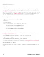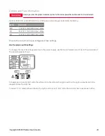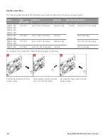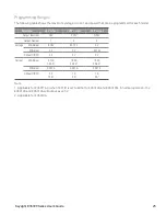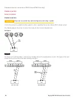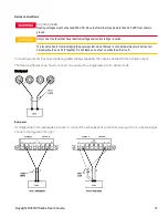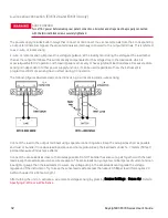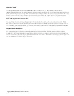
1. Connect the instrument to the computer using a LAN crossover cable. Alternatively, connect the computer and
the instrument to a standalone hub or switch using regular LAN cables.
Make sure your computer is configured to obtain its address from DHCP and that NetBIOS over TCP/IP is
enabled. Note that if the computer had been connected to a site LAN, it may still retain previous network set-
tings from the site LAN. Wait one minute after disconnecting it from the site LAN before connecting it to the
private LAN. This allows Windows to sense that it is on a different network and restart the network con-
figuration.
2. The factory-shipped instrument LAN settings are configured to automatically obtain an IP address from a site
network using a DHCP server. You can leave these settings as they are. Most Keysight products and most
computers will automatically choose an IP address using auto-IP if a DHCP server is not present. Each assigns itself
an IP address from the block 169.254.nnn. Note that this may take up to one minute. The front panel LAN indicator
will come on when the LAN port has been configured.
Turning off DHCP reduces the time required to fully configure a network connection when the power supply is
turned on. To manually configure the instrument LAN settings, refer to
Remote Interface Configuration
for
information about configuring the LAN settings from the front panel of the instrument.
3. Use the Connection Expert utility of the Keysight IO Libraries Suite to add the power supply and verify a
connection. To add the instrument, you can request the Connection Expert to discover the instrument. If the
instrument cannot be found, add the instrument using its hostname or IP address.
If this does not work, refer to “Troubleshooting Guidelines” in the Keysight Technologies USB/LAN/GPIB Inter-
faces Connectivity Guide included with the Keysight IO Libraries Suite.
4. You can now use Interactive IO within the Connection Expert to communicate with your instrument, or you can
program your instrument using the various programming environments. You can also use the Web browser on your
computer to communicate with the instrument as described under
.
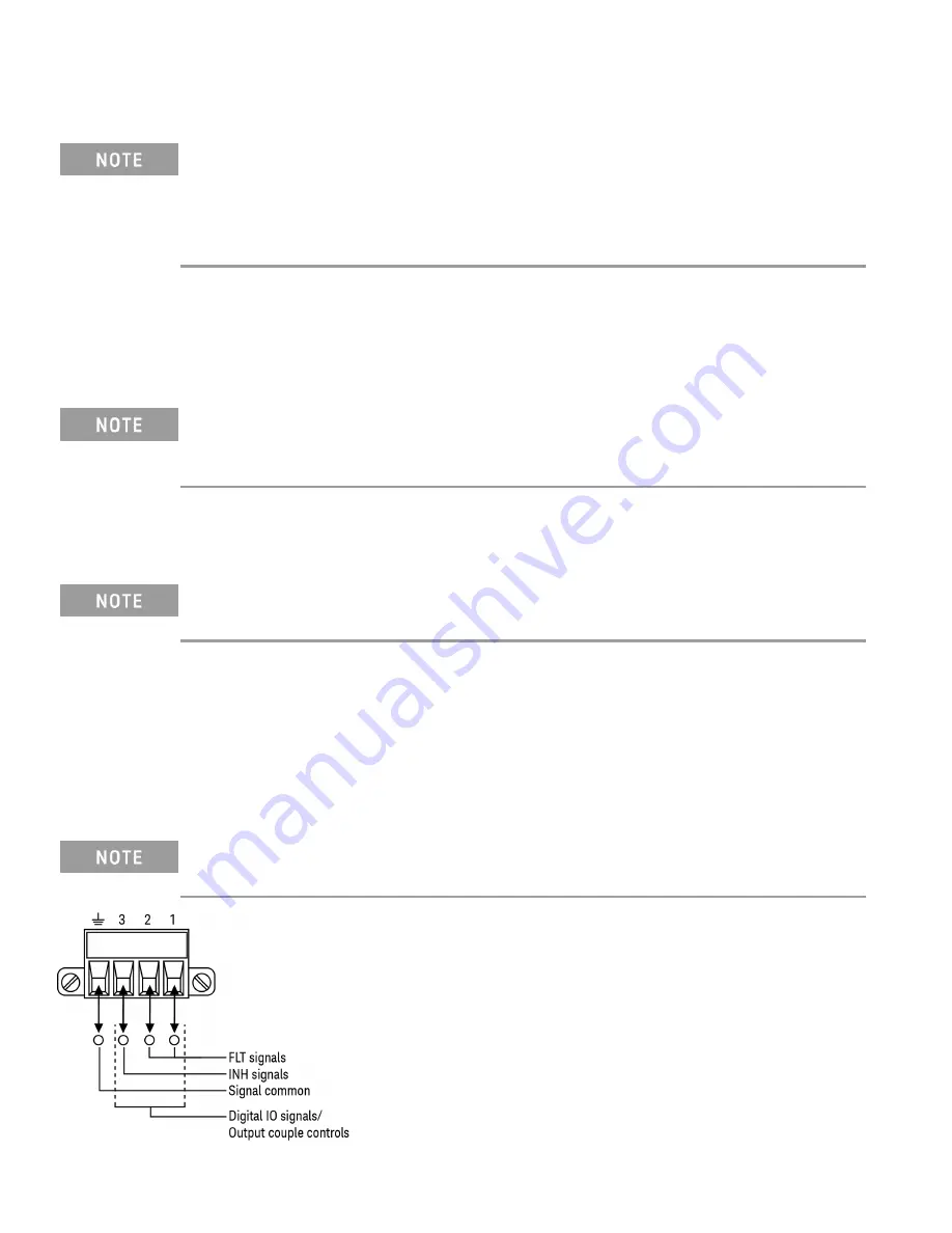
Digital port connections (E36312A and E36313A only)
A 4-pin connector is provided on each instrument to access the three digital control port functions. The digital
control connector accepts wire sizes from AWG 16 to AWG 22.
It is good engineering practice to twist and shield all signal wires to and from the digital connectors. If shiel-
ded wire is used, connect only one end of the shield to the chassis ground to prevent ground loops.
36
Keysight E36300 Series User's Guide
Содержание E36300 Series
Страница 1: ...User s Guide E36300 Series Programmable DC Power Supplies ...
Страница 12: ...12 Keysight E36300 Series User s Guide ...
Страница 29: ...Front panel Rear panel E36312A and E36313A only Keysight E36300 Series User s Guide 29 ...
Страница 106: ...106 Keysight E36300 Series User s Guide ...

