1
Introduction
14
Keysight 85331B/85332B Operating and Service Guide
Drive levels/Switch operation logic
Solid state PIN diode switches must always be connected to an active bias supply
source to either ON (low insertion loss state) or OFF (high isolation state).
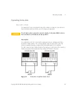
illustrates the switch port match definitions during ON and OFF states.
Contrary to the normal mechanical latching feature of electromechanical coaxial
switches, there is no way to latch a solid state switch in the ON or OFF state with
the power source removed.
A solid state switch which is not powered will exhibit neither the low insertion loss
nor high isolation characteristics, but rather some intermediate value of loss
through all paths.
Figure 1-3
Switch port match definitions for switch ON/OFF states
shows the pin locations on the bias connector. The notch and red mark
on the bias connector outer ring are used as reference.
NOTE
Only one port can be turn ON at a time, or all ports can be OFF. The total current
is approximately 480 mA for 85332B and 240 mA for 85331B with all ports OFF.
Содержание 85331B
Страница 1: ...Keysight 85331B 85332B Solid State Switch Operating and Service Guide ...
Страница 4: ...4 Keysight 85331B 85332B Operating and Service Guide THIS PAGE HAS BEEN INTENTIONALLY LEFT BLANK ...
Страница 6: ...6 Keysight 85331B 85332B Operating and Service Guide THIS PAGE HAS BEEN INTENTIONALLY LEFT BLANK ...
Страница 8: ...8 Keysight 85331B 85332B Operating and Service Guide THIS PAGE HAS BEEN INTENTIONALLY LEFT BLANK ...
Страница 10: ...10 Keysight 85331B 85332B Operating and Service Guide THIS PAGE HAS BEEN INTENTIONALLY LEFT BLANK ...

