


Preparing for Imaging
5
Keysight 5500 SPM User’s Guide
5-2
voltages to opposite piezo elements in the scanner so that one element
elongates and the other contracts.
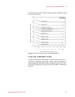
The scanner mounting fixture supplied with your system is designed to
keep the scanner and its components safe during handling (
The main cutout safely holds the scanner, while the smaller cutout
safely holds a nose assembly. A magnetic disk keeps additional tools
close at hand.
Figure 4-1
Scanner mounting fixture with nose assembly and spring
key; scanner in mounting fixture
The next sections will describe how to safely handle the scanner
components for long life and excellent imaging.
One-Piece Nose Assembly
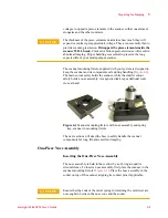
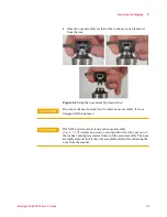
Inserting the One-Piece Nose Assembly
The nose assembly is held in the scanner by an O-ring around its
circumference. To insert a nose assembly, first place the scanner in the
scanner mounting fixture (
). Place the nose assembly in the
socket on top of the scanner, aligning its contact pins if applicable.
CAUTION
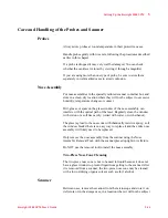
The thickness of the piezo elements determines how much they will
expand or contract per applied unit voltage. They are necessarily thin to
provide scanning resolution.
If dropped, the piezo elements inside the
scanner WILL break.
Cracked or broken piezoelectrodes will result in
abnormal imaging. Proper handling is essential to preserve the long
expected life of your multi-purpose scanner.
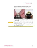
CAUTION
Ensure that the ends of the metal spring for retaining the cantilever are
not caught in between the nose cone and the socket.
Содержание 5500
Страница 1: ...Keysight 5500 Scanning Probe Microscope User s Guide ...
Страница 2: ......
Страница 9: ...Read This First N9410 90001 Keysight 5500 SPM User s Guide ix Declaration of Conformity ...
Страница 174: ...Additional Imaging Modes 5 Keysight 5500 SPM User s Guide 5 40 Figure 7 23 Plug in Images window ...
Страница 215: ...Closed Loop Scanners 5 Keysight 5500 SPM User s Guide 5 17 Save the calibration file X Y Z calibration is now complete ...
Страница 274: ...Temperature Control 5 Keysight 5500 SPM User s Guide 5 8 Figure 13 10 7500 9500 hot sample plate wiring diagram ...
Страница 275: ...Temperature Control 5 Keysight 5500 SPM User s Guide 5 9 Figure 13 11 5500 hot MAC sample plate wiring diagram ...
Страница 276: ...Temperature Control 5 Keysight 5500 SPM User s Guide 5 10 Figure 13 12 7500 9500 hot MAC sample plate wiring diagram ...
Страница 284: ...Temperature Control 5 Keysight 5500 SPM User s Guide 5 18 Figure 13 21 5500 Peltier Cold sample plate wiring diagram ...
Страница 297: ...Thermal K 5 Keysight 5500 SPM User s Guide 5 9 Figure 14 8 Select units after calibrating the Force Constant ...
Страница 330: ...Keysight Technologies 5500 SPM User s Guide Part Number N9410 90001 Revision H Keysight Technologies 2015 ...


