


56
57
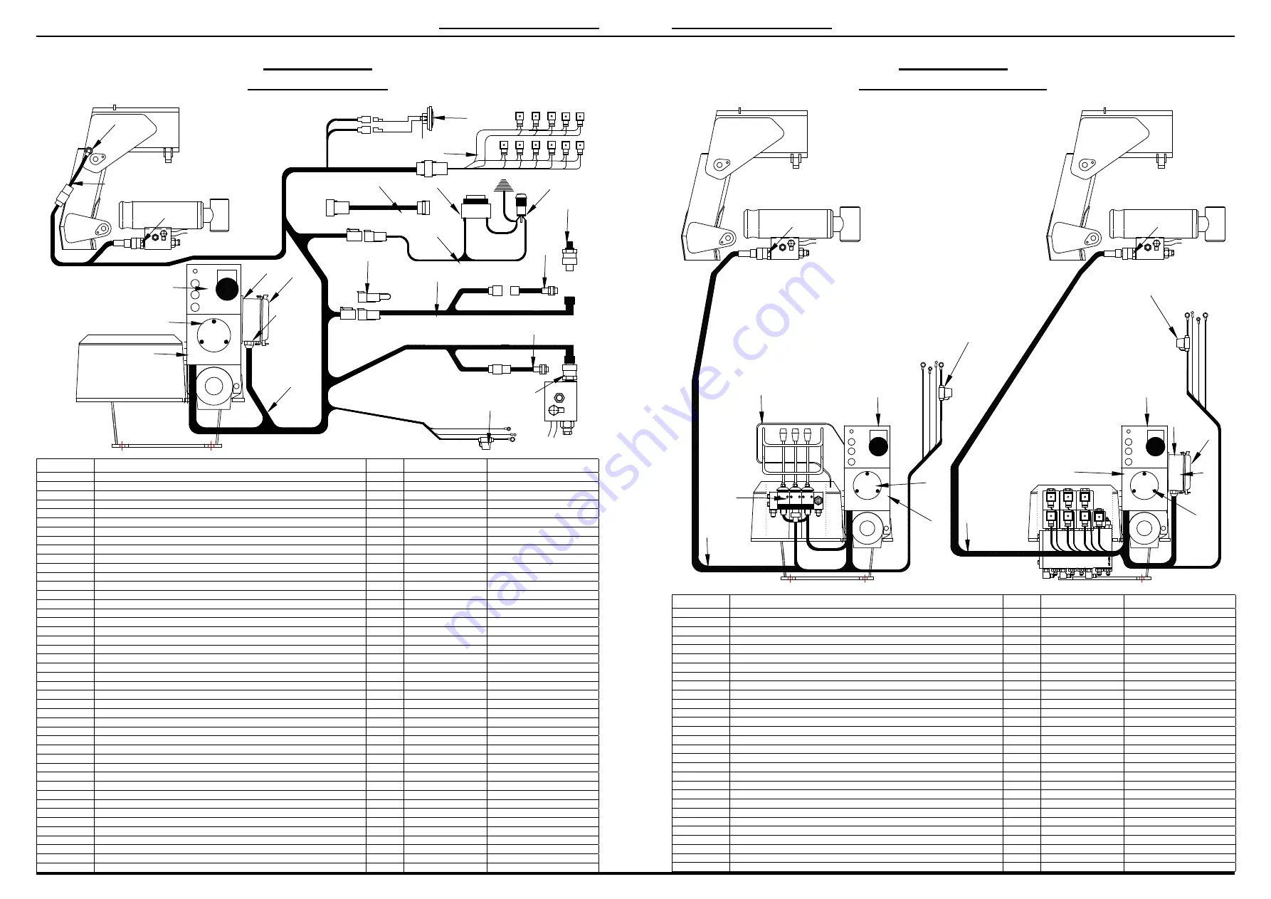
Load Limiter
K1500 - 3 Sensors
Item No.
Description
QTY
Notes
Order Part No.
1
1500 Load Limiter Controller
1
1500/30/1
2
Load Limiter Wiring Loom – Electric DCV
1
1500/30/2
3
Load Limiter Loom – 2nd Hydraulic Stabiliser Leg
1
1500/30/3
4
Loom Extension Electric DCV – 1m
1
Option
1500/30/4
5
Replacement Loom – DIN Plugs
1
1500/30/5
6
Load Limiter Housing
1
1000/30/15/A
7
Pressure Transducer
2-3
1000/30/6
8
Proximity Switch M12 4 Pin – Boom
1
1000/30/27/A
9
Proximity Switch M12 Wired – Hydraulic Leg/s
1-2
1000/30/27
10
Proximity Switch 90 Degree Wired Connector – Boom
1
1000/30/27/B
11
Termination Plug – Single Hydraulic Leg
1
1000/30/18/C
12
Cover Plate – Load Limiter Housing
1
1000/30/15/COVER
13
Warning Light – Leg/Boom Cab Mounted 12 volt
1
1000/30/23
14
Warning Light – Leg/Boom Cab Mounted 24 volt
1
1000/30/23/A
15
Warning Buzzer – Leg Boom Cab Mounted 12-48 V
1
1000/30/22
16
Horn 12 volt
1
1000/30/26
17
Horn 24 volt
1
1000/30/26/A
18
Warning Light/Buzzer Wiring Loom
1
1000/30/22/A
19
16 Pin Connector Base
1
1000/24/15
20
16 Pin Connector – Female Insert
1
1000/24/16
21
16 Pin Connector Replacement Lid
1
1000/24/15/B
22
Blade Fuse – 5 amp
1
1000/2/14/A
PARTS BREAKDOWN
Load Limiter
K1000/K1500 - 1 Sensor
Item No.
Description
QTY
Notes
Order Part No.
1
1000/1500 Load Limiter Controller 1 Sensor
1
1000/30/18
2
Wiring Loom to suit Manual DCV
1
1000/30/18/A
3
Wiring Loom to suit Electric DCV
1
1000/30/18/B
4
Load Limiter Housing
1
1000/30/15/A
5
Load Limiter Housing Cover Plate
1
1000/30/15/COVER
6
Pressure Transducer
1
1000/30/6
7
“X” Spool Valve Section Dual Throw Switch
1
1000/2/10/X/DS
8
Blade Fuse – 5 amp
1
1000/2/14/A
9
10 Pin Plug Base
1
1000/22/15
10
10 Pin Insert – Female
1
1000/22/16
11
Replacement Lid – 10 Pin Plug Base
1
1000/22/15/A
12
DCV Bump Guard Complete
1
1000/1/33
100%
EMERGENCY
STOP
POWER
CRANE LOADING
90%
+
-
1
12
6
2
20
21
19
7
10
8
16/17
5
4
15
13/14
18
7
9
3
11
9
22
7
100%
EMERGENCY
STOP
POWER
CRANE LOADING
90%
100%
EMERGENCY
STOP
POWER
CRANE LOADING
90%
1
1
2
3
4
4
5
5
6
6
7
8
8
9
10
11
12
NOTE;
WHEN BLUE & WHITE WIRE GOES TO POWER IT
IS CONFIGURED FOR A K1500, WHEN THE BLUE & WHITE
WIRE GOES TO EARTH IT IS CONFIGURED TO A K1000
PARTS BREAKDOWN