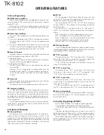
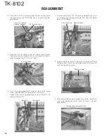
background image

TK-8102

2

INTRODUCTION

SCOPE OF THIS MANUAL

This manual is intended for use by experienced techni-

cians familiar with similar types of commercial grade commu-
nications equipment.  It contains all required service informa-
tion for the equipment and is current as of this publication
date.  Changes which may occur after publication are covered
by either Service Bulletins or Manual Revisions, which are
issued as required.

ORDERING REPLACEMENT PARTS

When ordering replacement parts or equipment informa-

tion, the full part identification number should be included.
This applies to all parts : components, kits, and chassis. If the
part number is not known, include the chassis or kit number
of which it is a part and a sufficient description of the required
component for proper identification.

PERSONAL SAFETY

The following precautions are recommended for personal

safety :
• DO NOT transmit if someone is within two feet (0.6

meter) of the antenna.

• DO NOT transmit until all RF connectors are secure and

any open connectors are properly terminated.

• SHUT OFF this equipment when near electrical blasting

caps or while in an explosive atmosphere.

• All equipment should be properly grounded before power-

up for safe operation.

• This equipment should be serviced by only qualified tech-

nicians.

PRE-INSTALLATION CONSIDERATIONS

1. UNPACKING

Unpack the radio from its shipping container and check for

accessory items. If any item is missing, please contact
KENWOOD immediately.

2. LICENSING REQUIREMENTS

Federal regulations require a station license for each radio

installation (mobile or base) be obtained by the equipment
owner. The licensee is responsible for ensuring transmitter
power, frequency, and deviation are within the limits permit-
ted by the station license.

Transmitter adjustments may be performed only by a li-

censed technician holding an FCC first, second or general
class commercial radiotelephone operator’s license. There is
no license required to install or operate the radio.

3. PRE-INSTALLATION CHECKOUT
3-1. Introduction

Each radio is adjusted and tested before shipment. How-

ever, it is recommended that receiver and transmitter opera-
tion be checked for proper operation before installation.

3-2. Testing

The radio should be tested complete with all cabling and

accessories as they will be connected in the final installation.
Transmitter frequency, deviation, and power output should
be checked, as should receiver sensitivity, squelch operation,
and audio output. Signalling equipment operation should be
verified.

4. PLANNING THE INSTALLATION
4-1. General

Inspect the vehicle and determine how and where the ra-

dio antenna and accessories will be mounted.

Plan cable runs for protection against pinching or crushing

wiring, and radio installation to prevent overheating.

4-2. Antenna

The favored location for an antenna is in the center of a

large, flat conductive area, usually at the roof center. The
trunk lid is preferred, bond the trunk lid and vehicle chassis
using ground straps to ensure the lid is at chassis ground.

4-3. Radio

The universal mount bracket allows the radio to be

mounted in a variety of ways. Be sure the mounting surface
is adequate to support the radio’s weight. Allow sufficient
space around the radio for air cooling. Position the radio close
enough to the vehicle operator to permit easy access to the
controls when driving.

4-4. DC Power and wiring

1. This radio may be installed in negative ground electrical

systems only. Reverse polarity will cause the cable fuse to
blow. Check the vehicle ground polarity before installation
to prevent wasted time and effort.

2. Connect the positive power lead directly to the vehicle

battery positive terminal. Connecting the Positive lead to
any other positive voltage source in the vehicle is not rec-
ommended.

3. Connect the ground lead directly to the battery negative

terminal.

4. The cable provided with the radio is sufficient to handle

the maximum radio current demand. If the cable must be
extended, be sure the additional wire is sufficient for the
current to be carried and length of the added lead.

GENERAL

Содержание TK-8102

Страница 1: ...TION BACK COVER CONTENTS REVISED II This service manual applies to products with 50800001 or subsequent serial numbers In terms of the products with the serial numbers earlier than 50800001 refer to the TK 8102 service manual as per part No B51 8585 00 and B51 8585 10 Service Manual List Title Parts number Remarks Destination TX RX unit number Display unit number TK 8102 B51 8585 00 M X57 6300 20 ...

Страница 2: ...quired to install or operate the radio 3 PRE INSTALLATION CHECKOUT 3 1 Introduction Each radio is adjusted and tested before shipment How ever it is recommended that receiver and transmitter opera tion be checked for proper operation before installation 3 2 Testing The radio should be tested complete with all cabling and accessories as they will be connected in the final installation Transmitter f...

Страница 3: ...to the schematic diagrams printed circuit board views and align ment procedures contained in this manual Speaker jack cap Power input connector Antenna connector NOTE If you do not intend to use the 3 5 mm jack for the external speaker fit the supplied speaker jack cap to stop dust and sand from getting in GENERAL SYSTEM SET UP SYSTEM SET UP Merchandise received Choose the type of transceiver Tran...

Страница 4: ...volume level e key Press to decrease the volume level r key PF Programmable Function key The default setting of this key is None no function The programmable func tions available for this key are listed below t key PF Programmable Function key The default setting of this key is Monitor Other programmable functions avail able for this key are listed below y 1 2 3 4 keys Press to select a channel fr...

Страница 5: ...itor Used to release signalling press once or squelch press and hold for approximately two seconds when operating as a conventional It is also used to reset option signalling Scan ON OFF Press this key starts scanning Pressing this key stops scanning Talk around Press this key the transceiver uses the receive frequency and the tone for transmission The operator can call the other party directly wi...

Страница 6: ...tone sounds while the PTT button is held down The warning tone stops when the PTT button is released PTT ID PTT ID provides a DTMF ANI or MSK ID to be sent with every time PTT connect ID at beginning of transmission dis connect ID at end of transmission or both You can program PTT ID on or off for each group channel DTMF The contents of ID are programmed for each transceiver The transceiver is cap...

Страница 7: ...e user of the transceiver operating state Refer to the help file on the KPG 70D regarding the func tions that are not listed below Stun on tone When a stun code is received transpond tone sounds Stun off tone When a stun release code is received transpond tone sounds Group call tone Sounds when a group call with the correct DTMF option signalling is received repeats 7 times You can select yes or n...

Страница 8: ...n the Power is switched on user mode can be en tered immediately When the PC sends a command the radio enters PC mode When data is transmitted from transceiver the red LED blink When data is received by the transceiver the green LED blink In the PC mode 4CH LEDs MON LED and LED are turned on Notes The data stored in the personal computer must match model type when it is written into the EEPROM Att...

Страница 9: ...ram as the master 5 The other slave can be continuously cloned Carry out the operation in step 2 to 4 4 1 Adding the data password If the data password is set in the optional feature menu you must enter the password Master transceiver to activate a clone mode you can use 1 2 3 and 4 to configure the password The maximum length of the password is 10 digits 1 1 Power ON 2 1 4 LED and MON LED are tur...

Страница 10: ...e twice then connect it to Terminal A of the PCB Connect the remaining grouping of wires of the KCT 39 cable to Terminal B Terminal A Terminal B 7 Align the terminal B KCT 39 cable underneath the termi nal A cable align the speaker cable T07 1082 05 below both KCT 39 cables Speaker cable In this direction 8 Align all cable to the left side so as to avoid the Power Module Area Mount the shielding c...

Страница 11: ...are plug 2 both of which are supplied with the KCT 39 1 4 7 10 13 2 5 8 11 14 3 6 9 12 15 No Color Internal Name connector 1 Red CN2 1 SB 2 Pink CN3 1 IGN 3 Black CN2 3 GND 4 Brown CN3 3 DETO 5 Orange CN3 2 DATAI 6 Yellow CN2 8 FNC4 7 Green CN2 7 FNC3 8 Blue CN2 9 FNC5 9 Purple CN2 12 FNC8 10 Gray CN2 10 FNC6 11 White CN2 11 FNC7 12 NC NC 13 NC NC 14 Sky blue CN2 6 FNC2 15 Turquoise CN2 5 FNC1 Acc...

Страница 12: ...e functions of pins of CN2 and CN3 on the TX RX unit are shown in the TERMINAL FUNCTION section page 37 Fig 1 Fig 2 R267 CN3 R202 TX RX UNIT Component side Pins Connection Voice scrambler 12 pins lead wire 11 pins lead wire functions with connector A with connector B A A 12 B A 11 C A 10 D A 9 5 B 5 6 B 7 7 A 8 8 A 7 9 A 3 10 B 11 11 B 9 12 B 4 Setting With the KPG 70D Select External Devices from...

Страница 13: ...cable E37 1117 05 to the topside of the ST 909 Cable Connect point ST 909 5 Mount the ST 909 onto the TX RX PCB using the adhesive cushion on the underside of the ST 909 onto the left edge of the silk screen area Connect the cables to the two ter minals Terminals ST 909 mounted at edge of silk screened area 6 Adhere the 13 x 9 x 8 mm cushion F G13 2006 04 to the top side of the ST 865KW4 between t...

Страница 14: ...ion A is replaced by cushion F Cushion B is replaced by cushion E 8 Align the connector on the underside of the ST 865KW4 with the connector on the top side of the ST 909 then press down on cushion E to secure them Cushion E ST 865KW4 ST 909 9 Flatten the cable so as to avoid potential damage when mounting the shielding cover Mount the shielding cover and secure it with the five M2 6 screws Screw ...

Страница 15: ...the display unit PCB detach the PCB by lifting at the indents of the PCB as shown below Fig 3 Tabs Tabs Tabs Indents Fig 5 5 When mounting the front panel match the 4 tabs of the chassis with the panel being sure they attach securely Tabs Tabs 4 Mount the display unit To mount the display unit on the panel follow the correct procedures shown to ensure easy display unit assembly and good fitting on...

Страница 16: ...IF SYSTEM PLL VCO 16 8MHz 50 4MHz ANT RX TX SP MIC Fig 1 Frequency configuration IF Amplifier The first IF signal is amplified by Q351 and the enters IC301 FM processing IC The signal is heterodyned again with a second local oscillator signal within IC301 to create a 450kHz second IF signal The second IF signal is then fed through a 450kHz ceramic filter Wide CF301 Narrow CF302 to further eliminat...

Страница 17: ...IC251 IC161 W NO EVOL2 AF PA IC252 SP IF IC IC301 Q301 NOISE AMP D301 IC301 IC101 AFO RSSI DET CPU IF SYSTEM SQIN RSSI Fig 3 Wide Narrow switching circuit Fig 4 AF signal system Fig 5 Squelch circuit PLL Frequency Synthesizer The PLL circuit generates the first local oscillator signal for reception and the RF signal for transmission PLL The frequency step of the PLL circuit is 5 or 6 25kHz A 16 8M...

Страница 18: ...equency harmonic components and the resulting signal is goes the antenna ter minal APC Circuit The automatic transmission power control APC circuit detects the power amplifier IC502 output with a diode D606 D607 and applies a voltage to IC501 IC501 com pares the APC control voltage PC generated by the D A con verter IC161 and DC amplifier IC203 with the detection output voltage IC501 generates the...

Страница 19: ...trix of the KMI1 to KMO2 ports of the microprocessor The KMO1 to KMO2 ports are always high while the KMI1 to KMI4 ports are always low The microprocessor monitors the status of the KMI1 to KMO2 ports If the state of one of the ports changes the microprocessor assumes that the key at the matrix point cor responding to that port has been pressed Encode The QT and DQT signals are output from QT DQT ...

Страница 20: ... Fig 16 Power supply circuit CIRCUIT DESCRIPTION Power Supply Circuit When the power switch on the display unit is pressed the power port on the display unit which is connected port 17 POWER goes low then port 82 SBC goes high Q32 turns on SB SW Q31 turns on and power SB is supplied to the radio When the DC power supplied to the radio the voltage regulator IC IC33 supply into the CPU VDD and reset...

Страница 21: ...rt 3 44 CEFLS I O CE for flash 45 46 FNC4 FNC5 I O Function port 4 5 47 48 FNC7 FNC6 I O Function port 7 6 49 FNC8 I O Function port 8 50 AFM O AF mute 51 SPM O Speaker mute Pin No Name I O Function 52 AMPSW O AF AMP switch 53 DT O Common data 54 CK O Common clock 55 56 NC I 57 59 DST1 DST3 I Destination 1 3 60 VCC 5V 61 NC I 62 VSS GND 63 NC I 64 NARROW O 65 WIDE O 66 68 NC I 69 CL O Clock for LC...

Страница 22: ...ncy MIC mute Active when MICEM is H Q251 Transistor Buffer amplifier RX audio Ref No Parts name Description Q252 253 FET AF mute Active while AFM is H Q254 Digital transistor AF mute Active while SPM is H Q255 Transistor AF mute Active while AMPSW is H Q301 Transistor SQL amplifier Noie amplifier Q302 Transistor Buffer amplifier 16 8MHz 3rd over tone Q351 Transistor IF amplifier Q352 FET Mixer Q35...

Страница 23: ...Y 52 3A T07 0739 05 SPEAKER D1 4 B30 2238 05 LED Y D5 10 B30 2239 05 LED SY D11 B30 2237 05 LED YG D12 B30 2240 05 LED SR C4 CK73GB1H103K CHIP C 0 010UF K C8 17 CK73GB1H103K CHIP C 0 010UF K C18 CK73GB1A105K CHIP C 1 0UF K C25 CK73GB1H103K CHIP C 0 010UF K C27 CK73GB1C104K CHIP C 0 10UF K CN1 E40 6005 05 FLAT CABLE CONNECTOR J1 E08 0877 05 MODULAR JACK L1 L92 0138 05 FERRITE CHIP CP3 4 RK75GB1J392...

Страница 24: ...GB1H471K CHIP C 470PF K C282 C92 0722 05 ELECTRO 470UF 16WV C283 CK73GB1H102K CHIP C 1000PF K C301 C92 0507 05 CHIP TAN 4 7UF 6 3WV C302 CK73GB1H102K CHIP C 1000PF K M M2 C302 303 CK73GB1H102K CHIP C 1000PF K M3 C303 CK73GB1H472K CHIP C 4700PF K M M2 C304 305 CC73GCH1H121J CHIP C 120PF J M3 C304 305 CC73GCH1H221J CHIP C 220PF J M M3 C306 CK73GB1H102K CHIP C 1000PF K C307 CK73GB1E223K CHIP C 0 022U...

Страница 25: ...F K C463 464 CK73GB1H471K CHIP C 470PF K C466 CC73GCH1H050B CHIP C 5 0PF B C467 CK73GB1H471K CHIP C 470PF K C501 CK73GB1H471K CHIP C 470PF K C502 CC73GCH1H020B CHIP C 2 0PF B M M2 C502 CC73GCH1H050B CHIP C 5 0PF B M3 C504 505 CK73GB1H471K CHIP C 470PF K C507 CK73GB1H471K CHIP C 470PF K C509 CC73GCH1H050B CHIP C 5 0PF B C510 515 CK73GB1H471K CHIP C 470PF K C516 CC73GCH1H080B CHIP C 8 0PF B C520 522...

Страница 26: ...3 3K J 1 16W R5 RK73GB1J223J CHIP R 22K J 1 16W R31 RK73GB1J472J CHIP R 4 7K J 1 16W R32 R92 1201 05 CHIP R 220 J 1 2W R33 RK73GB1J473J CHIP R 47K J 1 16W R34 RK73GB1J472J CHIP R 4 7K J 1 16W R35 RK73GB1J473J CHIP R 47K J 1 16W R36 RK73GB1J152J CHIP R 1 5K J 1 16W R37 RK73GB1J103J CHIP R 10K J 1 16W R38 RK73GB1J334J CHIP R 330K J 1 16W R39 RK73GB1J474J CHIP R 470K J 1 16W R40 RK73GB1J394J CHIP R 3...

Страница 27: ...IP R 27K J 1 16W M2 R311 RK73GB1J333J CHIP R 33K J 1 16W M M3 R312 RK73GB1J154J CHIP R 150K J 1 16W M2 R312 RK73GB1J473J CHIP R 47K J 1 16W M M3 R313 RK73GB1J104J CHIP R 100K J 1 16W R314 RK73GB1J222J CHIP R 2 2K J 1 16W R315 RK73GB1J183J CHIP R 18K J 1 16W R316 RK73GB1J223J CHIP R 22K J 1 16W R317 320 RK73GB1J103J CHIP R 10K J 1 16W R321 RK73GB1J223J CHIP R 22K J 1 16W R322 RK73GB1J101J CHIP R 10...

Страница 28: ...2B470J CHIP R 47 J 1 8W R537 RK73GB1J152J CHIP R 1 5K J 1 16W R538 R92 0679 05 CHIP R 0 OHM R539 R92 1213 05 CHIP R 100 J 1 2W R601 602 RK73GB1J223J CHIP R 22K J 1 16W R603 RK73GB1J473J CHIP R 47K J 1 16W R605 RK73GB1J473J CHIP R 47K J 1 16W R606 RK73GB1J102J CHIP R 1 0K J 1 16W R800 R92 1061 05 JUMPER REST 0 OHM D1 11 DA221 DIODE D31 ZSH5MA27 SURGE ABSORBER D32 1812L110PR VARISTOR D61 02DZ18 X Y ...

Страница 29: ...esti nation New parts TX RX UNIT X57 6920 XX Q407 2SJ243 FET Q408 KRX102U TRANSISTOR Q410 411 2SC5108 Y TRANSISTOR Q440 2SC4617 S TRANSISTOR Q500 2SC5108 Y TRANSISTOR Q501 502 2SC3357 TRANSISTOR TH97 98 B57331V2104J THERMISTOR TH301 B57331V2104J THERMISTOR TH351 NCP18XW332J03 THERMISTOR TH401 NCP18XH103K03 THERMISTOR M ...

Страница 30: ... B B Part name label face down A M3 x 8 N67 3008 46 B M2 6 x 6 Br Tap N87 2606 46 C M2 6 x 14 Br Tap N87 2614 46 1 34 21 22 26 IC502 20 13 36 25 10 2 30 8 15 48 14 52 35 3 5 27 Q31 IC252 701 S No label Display unit Parts with the exploded numbers larger than 700 are not supplied ...

Страница 31: ...0016 05 x 2 38 Inner packing case H02 0617 02 39 Polystyrene foamed fixture H10 6636 13 42 Protection bag H25 2320 04 41 Protection bag H25 0103 04 40 Polystyrene foamed fixture H10 6639 03 43 Item carton case H52 1699 12 7 Instruction manual B62 1389 10 Parts with the exploded numbers larger than 700 are not supplied ...

Страница 32: ...r 20A 8 AF Volt Meter Frequency Range 50Hz to 10kHz AF VTVM Voltage Range 1mV to 3V 9 Audio Generator AG Frequency Range 20Hz to 20kHz or more Output 0 to 1V 10 Distortion Meter Capability 3 or less at 1kHz Input Level 50mV to 10Vrms 11 4Ω Dummy Load Approx 4Ω 10W or more 12 Regulated Power Supply 13 6V approx 20A adjustable from 9 to 17V Useful if ammeter requipped 13 Spectrum Analyzer Center fre...

Страница 33: ...ed before mounting the shield cover as below Fuse To mount the fuse the cable terminal direction must be as follow Locator Speaker cable This side up This side up Cable terminal Cable terminal Fuse Pin 1 marker Part name label face down TX RX unit Component side IC252 Power MIC jack 1 2 3 4 keys Volume up down key key Speaker Display TX RX unit Component side 8T RESET CNVSS 5M B E TEMP2 POWER RXD ...

Страница 34: ...pass CH RX low Wide Spectrum analyzer BPF TC353 to Fig 1 filter CH RX high Wide 2 Track generator output 30dBm Connect the spectrum analyzer to BPF terminal Item Condition Test equipment Terminal Parts Method Specifications Remarks Measurement Adjustment Fig 1 Test Frequency MHz Channel M M2 M3 TX RX TX RX TX RX 1 Center 470 100 470 050 502 600 502 550 415 100 415 050 2 Low 450 100 450 050 485 100...

Страница 35: ...X center Wide Narrow CH RX high Wide 2 SSG output 120dBm 0 22µV Wide 119dBm 0 25µV Narrow Mod 1kHz Dev 3 0kHz Wide Dev 1 5kHz Narrow Item Condition Test equipment Terminal Parts Method Specifications Remarks Measurement Adjustment ADJUSTMENT Transmitter Section 1 Frequency 1 CH TX center Frequency counter ANT PC key Adjust to center frequency Within 100Hz 2 Transmit 2 Maximum 1 CH TX high Power me...

Страница 36: ... MIC 2 0kHz Narrow CH TX high Wide LPF 15kHz According to the large 2 AG 1kHz 50mV Oscilloscope 3 Transmit AG AF V M 7 MIC 1 CH TX center Wide Narrow Check 3kHz 0 2kHz sensitivity 2 AG 1kHz 5mV Wide 3 Transmit 1 5kHz 0 1kHz Narrow 8 DQT 1 CH TX low Wide Modulation analyzer 0 75kHz Wide 0 05kHz deviation CH TX center Wide Narrow or Linear detector 0 35kHz Narrow CH TX high Wide LPF 3kHz 2 Transmit ...

Страница 37: ...NC5 Scrambler Code1 1 O FNC6 Scrambler Code2 2 O FNC7 Scrambler Code3 4 O FNC8 Scrambler Code4 8 O Port Function is Low Active Exclude Scrambler Code CN3 No Name I O Function 1 IGN I Ignition sens input 2 DATAI I External transmit signal input 3 DETO O FM detector output 4 TXAFI I TX audio input from scrambler board 5 TXAFO O TX audio output to scrambler board 6 EMGMIC I Emergency MIC input 1kHz 1...

Страница 38: ...D11 D12 POWER UP DOWN 1 2 3 HOOK CM PTT MIC SB MBL GND ME C25 Q10 C8 C9 IC1 1 8 9 16 R10 R11 R13 R14 R15 R16 R17 Q4 Q9 R9 CP3 CP4 C11 C12 C13 C15 C17 DISPLAY UNIT X54 3460 20 Component side view J72 0916 09 DISPLAY UNIT X54 3460 20 Foil side view J72 0916 09 TK 8102 PC BOARD ...

Страница 39: ... 16 R12 R18 R19 R20 R1 R2 R3 R4 R5 R6 R7 R8 C10 C14 C15 C16 C18 DISPLAY UNIT X54 3460 20 Component side view J72 0916 09 DISPLAY UNIT X54 3460 20 Foil side view J72 0916 09 Ref No Address D1 7K D2 7G D3 3N D4 3D D5 3K D6 4K D7 5F D8 5H D9 5J D10 5L D11 4H D12 3G Ref No Address IC1 11J Q4 11G Q9 11B Q10 11B D13 11L PC BOARD TK 8102 Component side Foil side Layer 1 Layer 2 Component side Foil side L...

Страница 40: ...15 R16 R17 R18 R19 R20 Q4 Q9 R1 R2 R3 R4 R5 R6 R7 R8 R9 CP3 CP4 C10 C11 C12 C13 C14 C15 C16 C17 C18 DISPLAY UNIT X54 3460 20 Component side view J72 0916 09 DISPLAY UNIT X54 3460 20 Component side view J72 0916 09 DISPLAY UNIT X54 3460 20 Foil side view J72 0916 09 DISPLAY UNIT X54 3460 20 Foil side view J72 0916 09 Ref No Address D1 7K D2 7G D3 3N D4 3D D5 3K D6 4K D7 5F D8 5H D9 5J D10 5L D11 4H...

Страница 41: ...3 C14 C15 R201 R202 C16 C17 C18 C19 J1 EXT SP Q31 B C E IC252 1 10 O G B C E I 1 DI CE SB KMI4 KMI3 CM HOOK POWER PTT CL 5C KMO2 KMO1 KMI1 KMI2 E MIC E 2 18 17 RESET CNVSS 5M S G D CN5 E SP B E TEMP2 G D POWER 1 12 CN2 SB NC E DETO2 FNC1 FNC2 FNC3 FNC4 FNC5 FNC6 FNC7 FNC8 RXD TXD S G D S G D CV 8C 5C RXAFI ALTI RXAFO EMGMIC TXAFO TXAFI DETO DATAI 11 S G D 11 20 1 2 TK 8102 PC BOARD TX RX UNIT X57 ...

Страница 42: ...R303 R304 R305 R306 R311 R312 R313 R314 R315 R316 R317 R318 R319 R512 R320 R321 R322 R323 R324 R527 R528 R529 R530 R531 R532 R533 C303 C304 C305 TH301 R538 R539 C310 C311 C312 C313 C314 R351 C315 R352 C316 C317 R353 R354 C318 R161 R355 C319 R162 R163 R164 R165 R166 C321 C322 C323 C324 C527 C538 R380 C539 C351 C353 C354 TH351 C355 C161 C162 C356 C163 C164 Q201 Q202 D302 D303 C559 C560 L403 L404 C57...

Страница 43: ... R165 R166 C321 C322 C323 C324 Q1 C522 C527 R31 R32 R1 R35 R2 R36 R3 R37 R5 C538 R380 C539 C151 C152 C351 C353 C354 TH351 C355 C161 C162 C356 C163 C164 Q201 Q202 D302 D303 C559 R61 Q402 R62 Q403 C560 L201 R71 R72 R73 R74 R75 R76 R77 L403 R78 L404 C571 C572 C573 R81 R82 IC501 CN1 C391 CN3 8T TH97 TH98 Q252 Q253 Q254 Q255 C10 C13 C14 C15 R201 R202 C16 R203 C17 R204 C18 R205 C19 R206 R207 R208 R209 J...

Страница 44: ...69 R370 R371 R372 R373 R374 R375 R376 R377 R378 C534 C537 R381 C357 C358 C359 C360 D301 C361 C362 C363 C364 C366 C367 Q404 C368 Q405 C369 TC352 Q407 TC353 Q408 C370 C371 C372 C373 Q410 C374 Q411 C375 C376 C377 C378 C379 C380 L4 C381 C382 C383 C384 L601 C385 L602 C386 L603 L604 L410 C388 C389 L417 L418 C390 C601 L420 Q440 Q251 D351 D352 D353 D354 D355 J72 0918 09 1 2 3 4 IC251 1 7 8 14 BPF 1 10 11 ...

Страница 45: ... R123 R125 R126 R127 R128 R129 D31 R511 R513 R514 R515 R516 R517 R130 R519 R131 CN501 CN502 R520 R521 R522 R523 R524 R525 C101 C102 R526 C104 R534 R535 R536 9 C511 C512 C513 C514 C516 C520 C521 C523 R33 R34 R4 R38 C531 R39 C532 C534 R40 R41 C540 Q405 Q406 R66 R67 R68 R69 D502 D503 Q410 R70 IC101 L405 L406 L407 L408 L409 L411 R86 L412 R87 L413 L414 L415 L416 L418 R91 R92 R93 R94 X86 B C E G S D G S...

Страница 46: ...R360 XF351 R361 R362 C326 R363 R364 R365 R366 R367 C520 C521 R369 C523 R370 R371 R372 R33 R373 R374 R34 R375 R376 R377 R4 R378 R38 C531 R39 C532 C534 C537 R40 R41 R381 C540 C357 C358 C359 C360 D301 C361 C362 C363 C364 C366 C367 Q404 C368 Q405 C369 Q406 R66 TC352 Q407 TC353 R67 Q408 R68 R69 D502 D503 C370 C371 C372 C373 Q410 R70 C374 IC101 Q411 C375 C376 C377 C378 C379 L405 L406 L407 C380 L408 L409...

Страница 47: ...p R213 330k C406 1000p D7 DA221 C18 470p 8C 2SK1824 Q86 C16 470p R215 68k R225 150k R404 10k R411 10k R416 470 R407 1 5k 30 X401 L77 1868 15 VC GND XOUT 5C R410 10k R227 22k R426 47k C434 29 R228 10k C210 0 1u C225 1u16 C205 0 1u C417 470p R221 15k R163 47k C421 470p C89 6p L414 R201 680 2SA1832 GR Q402 IC203 NJM2902V 1 2 3 4 V 5 6 7 8 9 10 11 GND 12 13 14 2SC4738 GR Q403 8C 8 L409 R78 1k C440 C90...

Страница 48: ...0 C373 L355 C371 0 5p C370 470p C372 15p C367 C368 7p R365 100k L354 C374 7p R366 100k C356 2p C354 6p TH351 3 3k C515 470p 1 QT DQT 2 DTMF MSK 3 PLLE 4 NC 5 NC 6 GND 7 CNVSS 8 EVLLD 9 BSHIFT 10 RESET 11 XOUT 12 VSS 13 XIN 14 VCC 15 GND 16 NC 17 POWER 18 INT 19 NC 20 TX RX 21 UL 22 NC 23 NC 24 NC 25 NC 26 27 28 29 30 31 32 33 34 35 36 37 38 39 40 41 42 43 44 45 46 47 48 49 50 51 52 53 54 55 56 57 ...

Страница 49: ...0 11 GND 12 13 14 C604 R3 1k R533 0 D606 MA742 R312 C305 C608 2p C61 470p C313 15u6 3 R308 330k R253 0 C38 470p C303 R256 5 6k R606 1k C49 0 01u C55 0 1u C602 1000p C391 470p D355 8n L360 C380 470p L361 8n C381 C389 0 01u R377 0 L358 R375 0 R374 100k C385 470p R376 100k TC353 6P R380 100k C390 TC352 R381 C388 C384 C382 470p C386 L359 C383 0 5p R378 100k C321 33p R279 4 7k R278 12k C275 1u C281 470...

Страница 50: ... 2p C523 C304 5p HVC350B HVC355B 27u 1p 27n 3p 4 7u 7p 6p L410 4p 6p HVC350B HVC350B R311 6p 270n TC402 C381 C439 270n 6p 270n 33n 6p D354 4p 270 6p 2p HVC350B 270n 9p 2p 12p L413 L412 7p 3p HVC355B 270n 10p 10 12 5n 270n 220 4p C388 NO C502 6p C431 27u C435 D353 270n 8n 2p R502 HVC355B 3p 7p 2p 270n 2p 10p 8p 5p C427 10K 39n D355 6p C384 2p 5n D351 C373 0 27u 180n L415 5p HVC350B HVC350B C611 220...

Страница 51: ...6 7 8 9 10 J1 C282 470u16 C274 0 22u CN5 Q255 KRC102S C30 1000p C29 470p C28 220p C48 C433 470p TH401 1 QT DQT 2 DTMF MSK 3 PLLE 4 NC 5 NC 6 GND 7 CNVSS 8 EVLLD 9 BSHIFT 10 RESET 11 XOUT 12 VSS 13 XIN 14 VCC 15 GND 16 NC 17 POWER 18 INT 19 NC 20 TX RX 21 UL 22 NC 23 NC 24 NC 25 NC 26 27 28 29 30 31 32 33 34 35 36 37 38 39 40 41 42 43 44 45 46 47 48 49 50 51 52 53 54 55 56 57 58 59 60 61 62 63 64 6...

Страница 52: ... TXD CM GND ME Q407 2SJ243 IC401 MB15A02 LIPPLE FILTER LD Q61 KRC404RTK DT INT KMI4 LOOP FILTER KMO1 HOOK RXD KMI2 TC D A CONV D A CONV D A CONV CM CV 5C Q402 2SA1832 GR KMI2 SB IC161 M62363FP 3 8 IC161 M62363FP 8 8 IC161 M62363FP 6 8 DTMF 5C PLLE DISPLAY UNIT X54 3460 20 Q4 2SK508 MICMT 5C CE CL DI Q1 2SK1824 X401 QT DQT TX R SPM AFM AMP CL CE DI 5C TXAFI IGN 5C TXAFO ALTI FNC2 RXD EMGMIC FNC1 TX...

Страница 53: ...5M SW VCOMOD E NARROW EEPROM Q252 253 2SK1824 8R RESET ROW IC33 NJM78L05UA 3 CPU IC101 30622MAA B87GP AVR BPF Q36 KRC102S Q254 DTC363EU IC161 M62363FP 3 8 IC161 M62363FP 4 8 8T Q406 2SK508NV K52 IC35 PST9140NR RESET X86 IC34 PST9140NR DTMF BEEP 8TC SQIN Q32 2SK1824 SBC Q251 2SC4617 S TXD 8C SPM MICEM SIGNAL Q34 KRC102S 8T SB B IF DEMODULATOR AF PA AFM SW MCF INT Q407 2SJ243 D602 MA4PH633 SW 8T 8T ...

Страница 54: ...To make measurements in the AF section connect the AC level meter AG is set so that MIC input becomes 3kHz 1 5kHz Wide Narrow DEV at 1kHz MOD D CF1 CF2 450kHz 7 IC203 TX RX Unit S IC301 5 49 95MHz 9 IC201 G1 20 1 Center Frequency W 121 0dBm N 120 5dBm W 119 0dBm N 118 5dBm W 105 5dBm N 105 5dBm W 106 0dBm N 105 0dBm W 1 05Vrms N 0 44Vrms W 0 49Vrms N 0 20Vrms W 117 5dBm N 117 0dBm W 103 0dBm N 101...

Страница 55: ...for a 0 45V 4Ω by the front panel AF VOL control Q406 vel meter 12dB SINAD TX RX Unit Q410 11 Q411 Power Module D409 TX RX Unit IC502 Audio Frequency Q500 TX RX Unit VCO CF1 CF2 450kHz Q501 IC301 D602 ANT 5dBm 17dBm 0dBm 11 5dBm 7dBm 25W W 93 0dBm N 91 0dBm W N 0 34Vrms W N 0 33Vrms W N 0 27Vrms W N 0 31Vrms W N 0 33Vrms W N 10mVrms W N 0 55Vrms W N 0 45Vrms 14 J1 IC161 12 Q251 8 9 12 4ohm 10 IC25...

Страница 56: ... LTD Unit 3712 3724 Level 37 Tower one Metroplaza 223 Hing Fong Road Kwai Fong N T Hong Kong KENWOOD ELECTRONICS SINGAPORE PTE LTD 1 Genting Lane 07 00 Kenwood Building Singapore 349544 TK 8102 GENERAL Frequency Range M 450 to 490MHz M2 485 to 520MHz M3 400 to 430MHz Channels Groups 4 channels Channel Spacing Wide 25kHz Narrow 12 5kHz PLL Channel Stepping 5 0 6 25kHz Operating Voltage 13 6V DC 15 ...

Отзывы: